Sanwa DG525 User manual

04.09猯
DIGITAL INSULATION METER
INSTRUCTION MANUAL

–1 –
[1] Safety Precautions — Be sure to read before use. —
Be sure to read carefully the information under “ WARNING” and
“CAUTION” in this manual in order to prevent human injuries,
electric shock and damage to the instrument as well as other
equipment.
1-1 Warning Markings and Other Symbols
The symbols and their meanings used with the instrument and in
this manual are as described below.
■The following markings are used to indicate especially important
information for safe use of the instrument.
The information under this marking must be
observed strictly to prevent human injuries,
including burns and electric shock.
The handling information under this marking
should be observed carefully to prevent damage
to the instrument and associated equipment.
■Other symbols used with the instrument and in this manual
Indicates a risk of shock due to a high voltage
generated or applied at a measuring terminal.
EInsulation resistance measurement terminal (Earth =
GND)
LInsulation resistance measurement terminal (Line)
ACV~ AC voltage
MΩInsulation resistance
INSUL.
TEST VOLT Insulation test voltage ON indication
ON
POWER Measuring power switch
HOLD Measurement value hold switch
LIGHT Back-light lighting switch
CAUTION
WARNING

–2 –
1-2 Warning Messages for Safety
1. Check the measurement type (insulation resistance or AC
voltage) before measurement and select the appropriate
function for it.
2. Do not apply a voltage or signal exceeding the specified
maximum allowable input. (For the maximum allowable
input voltage value, see section 1-3 on the next page.)
3. Do not open the case or battery cover unless replacing
the batteries as described in this manual.
4. Always use the specified test leads.
5. If the insulation coating of a test lead is damaged or its
conductor wire is exposed, do not attempt to repair it.
Instead, replace with a new test lead.
6. Do not switch the measuring function during measure-
ment.
7. Do not use the instrument when it is moistened, when
your hand is wet or when the ambient humidity is high
(85%RH or more).
8. Do not touch the metallic parts of the test leads during
measurement.
9. Do not use the instrument if it is defective and incapable
of making the specified measurements.
10.Do not use the instrument using high-power or higher-
voltage circuitry than the maximum allowable input.
11.Be sure to conduct annual inspections.
WARNING

–3 –
1-3 Maximum Allowable Input
Function Input Terminals Maximum Allowable Input
Insulation
resistance
ACV
E — MΩ— L
〜— ACV — 〜
Voltage or current
input prohibited
600 V AC
[2] Outline and Features
2-1 Outline
This instrument is a compact, handy high-performance digital
insulation tester with an additional AC voltage measuring function.
The characteristics of the voltages applied to the measuring
terminal during insulation resistance measurement are in compli-
ance with the output voltage characteristics specified in JIS C1302-
1994.
2-2 Features
1. Each instrument is capable of switching the voltages applied
during insulation resistance measurement in the following 2
ranges.
Model DG525: 500 V DC/250 V DC
Model DG251: 250 V DC/125 V DC
2. With both measuring functions, automatic range switching can
be used to switch the range according to the measurement
value.
3. Even when the user forgets to switch the power off after
measurement, the auto power OFF feature turns the power off
automatically in about 1 minute.
4. A back-light lamp is provided for easy readout, even in the dark.
5. The data hold feature holds the measurement value.
6. When the built-in batteries run out, the battery alarm display
indicates battery replacement timing.

–4 –
[3] External View and Names of Parts
(1) Measuring terminals
(Common for insulation
resistance and AC voltage)
(2) LCD (Liquid Crystal Display)
panel
(3) HOLD switch & indicator
(yellow LED)
(4) POWER switch
(5) INSUL. TEST VOLT ON
(Insulation test voltage ON)
indicator (red LED)
(6) Function switch
(7) LIGHT (back-light) switch
(8) Red test lead (for L/ 〜terminal)
(9) Black test lead (for E/ 〜
terminal)
(
10
)Aligator clip adapter
Reference When the point of (9) lead is inserted into clip adapter (10),
(9) will come to work as clip lead. It will make mesurement multipurpose.
TL-M54

–5 –
[4] Measurements
4-1 Preparation Before Measurement
For safe use of the instrument, check its appearance and
associated accessories carefully before use.
1. Check for damage due to dropping, etc.
2. There is a risk of electric shock if the insulation coating
of a test lead or its conductor wire is exposed. Check the
test leads carefully before use.
NOTE: Operation of the POWER Switch and Auto Power OFF
The POWER switch of the instrument toggles, or alternates
operation, so that each successive press switches the selected
measuring function from ON to OFF, and vice versa. The auto power
OFF feature provided turns power OFF automatically in about 1
minute, as a safeguard for when you forget to set the POWER
switch to OFF after use. Still, we recommend pressing the POWER
switch to OFF after measurement to save the power of the built-in
batteries.
NOTE: Operation of the HOLD Switch
To hold a measurement value, press the HOLD switch above the
POWER switch. The HOLD indicator (yellow LED) light up and the
current measurement value will be held in memory. Press the HOLD
switch again to clear the held value.
NOTE: Display Illumination by Back-Light
If the measurement value is hard to read under low light, press the
LIGHT switch on the bottom right of the panel.
The green back-light turns on to make the readout more visible. As
the back-light consumes power of the built-in batteries, we recom-
mend setting the LIGHT switch to off to save battery power when
measurement and readout are not required.
WARNING

–6 –
4-2 Checking the Built-in Batteries
1. Do not connect any leads to the measuring terminals.
2. Set the function switch to 500 V or 250 V with Model DG525 or
to 250 V or 125 V with Model DG251.
3. Press the POWER switch.
4. The built-in batteries are normal if the INSUL. TEST VOLT ON
indicator (red LED) lights up and the LCD looks as shown in
Fig. 1.
Fig. 1
5. If the INSUL. TEST VOLT ON indicator does not light and the
LCD shows nothing, even when the POWER switch is pressed to
ON, the batteries may be exhausted completely, or no battery
has been loaded. In this case, remove the battery cover on the
rear case and insert new batteries as described in section 4-3,
“Replacing the Built-in Batteries” on the next page.
6. If the INSUL. TEST VOLT ON indicator does not light and the
LCD shows nothing, although unexhausted batteries are loaded,
it is possible that the battery terminal contacts have failed. In this
case, remove the battery cover on the rear case and check the
contacts between the batteries and terminals.
7. If the INSUL. TEST VOLT ON indicator lights up but the LCD
shows the “B” marking as shown in Fig. 2 when the POWER
switch is pressed to ON, the built-in batteries are nearly
exhausted. In this case, replace them with new batteries.
Fig. 2

–7 –
4-3 Replacing the Built-in Batteries
1. Set the function switch to OFF on the center position.
Make sure that the function switch is set to OFF before
proceeding to the battery replacement operation.
2. Refer to Fig. 3 below for the battery replacement.
3. Remove the lock screw on the battery cover on the rear case,
then remove the battery cover by sliding it down while pushing the
square projection on the top center (Fig. 3[A]) with your finger, and
insert batteries in correct polarity positions as shown by Fig. 3[B].
4. After checking that the batteries have been inserted correctly,
place the battery cover in the original position on the rear case
and fasten with the lock screw.
1. Always use the specified batteries (LR6/AA size alkaline
batteries).
2. To prevent performance degradation, replace all six
batteries with six brand-new ones when the time comes
to replace batteries.
WARNING
Battery cover
3 mm lock
screw
• Battery cover
1.5 V LR6/AA size alkaline
batteries (x 6)
• Battery polarity
Fig. 3
Slide while
pushing
[A] [B]
CAUTION

–8 –
4-4 Measuring the Insulation Resistance (MΩ)
1. When the power is ON with the insulation resistance
measuring function selected (when the INSUL. TEST
VOLT ON indicator is lit), a high voltage for insulation
resistance measurement is applied across the E-L
terminals. To avoid the risk of electric shock, do not touch
the metallic parts of the test leads connected to the
measuring terminals.
2. Make sure that the object to be measured is not sub-
jected to voltage before proceeding to measurement.
3. Certain measurement objects (capacitive objects, for
example) may retain the voltage applied from this
instrument for some time after the completion of the
measurement.
1. Set the function switch according to the measurement object, to
500 V or 250 V with Model DG525 or to 250 V or 125 V with
Model DG251.
2. Connect the black plug of the black test lead to the E terminal on
the left and the amber plug of the red test lead to the L terminal
on the right as shown in Fig. 4.
Black
Red
Fig. 4
3. Connect the black clip to a measuring point on the measurement
object and the tip of the red test rod to the other point, and press
the POWER switch. The INSUL. TEST VOLT ON switch will light
up and the resistance measurement value will be shown on the
LCD.
WARNING

–9 –
4. When the measurement object has resistance of more than 2000
MΩ, the LCD shows the same over-input display as that displayed
when the measuring terminals are open, as shown in Fig. 1 under
section [4]4-2, “Checking the Built-in Batteries” on page 6.
5. After measurement, press the POWER switch again to OFF or
set the function switch to OFF.
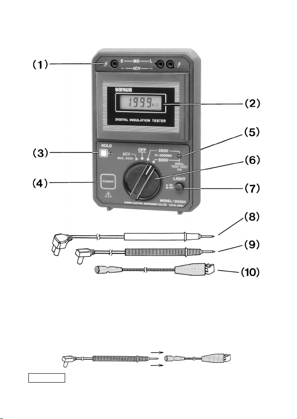
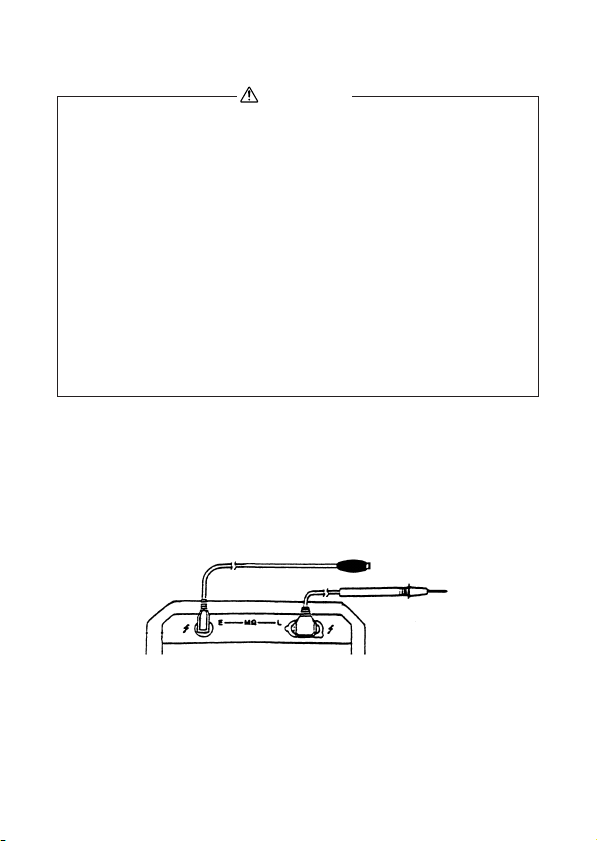
NOTE: Distinction Between E and L Terminals
When one of the measuring points is grounded, connect it to the E
terminal of the instrument.
This is specified in consideration of safe use, because the resis-
tance measurement value reading in the insulation testing can be
reduced in this way. In other measurement operations, consideration
of the polarity of measurement points is not necessary.
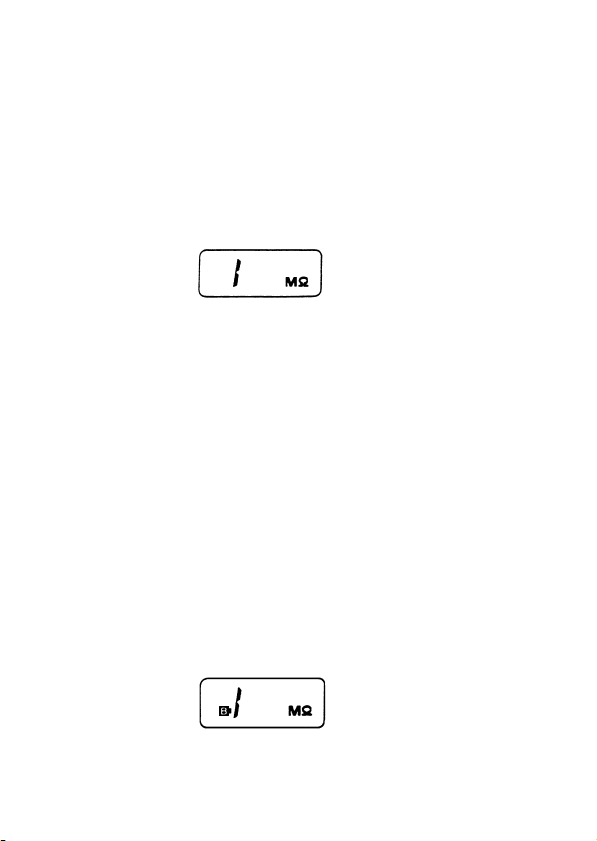
NOTE: In Case the “B” Marking is Displayed During Measurement
When the resistance measurement value in an insulation test is
extremely small, the LCD sometimes shows the “B” marking which
is usually used as the battery alarm indicator.
In the present case, the “B” marking is displayed because an
extremely small resistance measurement value means consumption
of large battery current and the drop in capacity due to exhaustion
of the batteries causes the internal operating voltage to fall below
the specified level.
4-5 Measuring the AC Voltage (ACV)
1. The maximum allowable input voltage of the ACV range is
600 V. Never apply a higher voltage than this.
2. Voltages higher than 25 Vrms AC are hazardous to the
human body. Be very careful during measurement.
3. Never attempt to change the function switch position
during measurement.
4. Never measure AC voltage with a wet hand.
WARNING

–10 –
1. Set the function switch to ACV.
2. Connect the amber plug of the red test lead to the ~(L) terminal
on the right and the black plug of the black test lead to the ~(E)
terminal on the left as shown in Fig. 4 under section [4]4-4,
“Measuring the Insulation Resistance” on page 8.
3. Press the POWER switch to ON, connect the black clip to a
measuring point on the measurement object, and apply the tip of
the red test rod to another measuring point. The LCD will show
the measurement voltage value.
4. After measurement, press the POWER switch again to OFF or
set the function switch to OFF.
[5] Maintenance & Management
This section contains important information for maintenance.
The maintenance of the instrument should be performed by
managing personnel who understand the instrument and this
manual in detail, and who are well-acquainted with handling
the instrument.
5-1 Maintenance & Inspections
Be sure to maintain and inspect to ensure safe, long-lasting,
optimum-performance use of the instrument.
1. Check that the external finish of the instrument is not damaged
due to dropping, etc.
2. Check the test leads to ensure that
•aplug is not loose when it is inserted into a terminal;
•the test lead coating is not damaged;
•the conductor wires are not exposed from any part of the test
leads.
WARNING
WARNING

–11 –
3. Check that the function switch is not subject to strong pressure
from above. (This could lead to a contact failure of the switch.)
If the instrument cannot comply with any of the above checks, do
not use it as it is. Service the defective part or replace it with a new
part.
5-2 Calibration
To maintain safety and accuracy, conduct inspections and
calibration at least every year.
For inspection and calibration, please consult a dealer in your
area or the local sales representative for the instrument.
5-3 Storage
1. The panel and rear case are not resistant to volatile
solvents or heat. Do not attempt to clean them with
lacquer thinner or alcohol, or place the instrument near a
source of heat.
To clean the instrument, wipe lightly with a soft, dry cloth.
2. Do not store the instrument in a place subject to vibration,
or where the instrument may drop.
3. Do not store the instrument under direct sunlight, under
extremely high or low temperatures, or in a place where
toxic gas is generated.
4. When the instrument is not used, be sure to set the
function switch to OFF.
5. When the instrument is not to be used for a long period of
time, be sure to remove the built-in batteries before
storing it.
WARNING
WARNING

–12 –
[6] Specifications
6-1 Insulation Resistance Measuring Block
1. Rated voltage DG525: 500 V DC/250 V DC, 2 ranges
DG251: 250 V DC/125 V DC, 2 ranges
2. Measuring voltage/current characteristics
When measuring terminals are open
DG525: 500 V DC range — 600 V (+20% max.)
> 500 V guaranteed at 500 kΩ
250 V DC range — 300 V (+20% max.)
> 250 V guaranteed at 250 kΩ
DG251: 250 V DC range — 300 V (+20% max.)
> 250 V guaranteed at 250 kΩ
125 V DC range — 150 V (+20% max.)
> 125 V guaranteed at 125 kΩ
When measuring terminals are shorted
Approx. 1.5 mA max.
3. Measuring ranges 0 to 2 MΩ/1 to 20MΩ/10 to 200MΩ/
100 to 2000MΩ, 4 auto range switching
4. Measuring accuracy 2 MΩ/20 MΩ/200 MΩranges:
Within ±(2% of reading + 2 digits)
2000 MΩrange:
Within ±(5% of reading + 2 digits)
5. Applied voltage indication
Red LED with 5 mm dia.
6-2 AC Voltage Measuring Block
1. Measuring range 0 to 600 V max.
0 to 200 V/10 to 600 V, 2 auto range
switching
2. Measuring accuracy Within ±(1% of reading + 0.5% of range +
1 digit)
Frequency: 50 to 400 Hz
3. Input resistance 1 MΩ

–13 –
6-3 Common Specifications
1. A/D converter Operating system: Double integration
Sampling rate: Approx. 2.5 samplings/sec.
2. Display LCD, max. 1999
3. Over-input indication Only the highest digit shows “1”.
4. Measuring terminals MΩ: E, L. ACV: 〜, 〜
5. Operating temperature/humidity range
0 to 40oC, ≤85%RH (without condensation)
6. Accuracy guaranteed temperature/humidity range
15 to 30oC, ≤80%RH (without condensation)
7. Built-in batteries 1.5 V LR6/AA size alkaline batteries (x 6)
8. Built-in battery life (time until battery voltage drops to 7 V)
When power is switched between ON and
OFF every minute in succession
Insulation resistance measurement
(measuring terminals open): Approx. 60 hours
AC voltage measurement: Approx. 250 hours
9. Battery alarm LCD shows “B” marking when battery
voltage drops below 7 V
10.Auto power OFF time Approx. 1 minute after power ON
11.Data hold Pressing HOLD switch holds measure-
ment value
HOLD indicator: Yellow LED with 3 mm dia.
12.Back-light lamp Pressing LIGHT switch lights up LCD
back light (green)
13.Dimensions & weight 175 x 115 x 55 mm, approx. 600 grams
6-4 Accessories
1. Red test lead with amber plug (L/ 〜terminal) x 1
2. Black test lead with black plug (E/ 〜terminal) x 1
3. Aligator clip adapter x 1
Set of the above 3 test leads: TL-M54
4. Instruction manual x 1
5. Carrying case C-M53 (with cord case) x 1 OPTION
The specifications in this manual may be subject to change for
performance improvement without notice.

–14 –
MEMO

04.09猯
DIGITAL INSULATION METER
INSTRUCTION MANUAL
This manual suits for next models
1
Table of contents
Other Sanwa Measuring Instrument manuals

Sanwa
Sanwa PDR302 User manual

Sanwa
Sanwa DCM2000DR User manual

Sanwa
Sanwa CAM600S User manual

Sanwa
Sanwa LCR700 User manual

Sanwa
Sanwa mobiken Series User manual

Sanwa
Sanwa RD700 User manual

Sanwa
Sanwa DCL1200R User manual

Sanwa
Sanwa DCM2000DR User manual

Sanwa
Sanwa YX360TRF User manual

Sanwa
Sanwa DCM400AD User manual