Black
D-1034-236 取扱説明書YX360TRF
オモテ・ウラ どん天
*1 Not including the resistance of fuse.
*2 The maximum value when the pointer was moved by
charged current in the capacitor.
DCVCV
DCACV
0.1 ±5% against
full scale
±5% against
full scale
±4% against
full scale
±3% against
full scale
±3% against
full scale
±3% against
full scale
±3% of arc
±5% of arc
Approximate Value
Approximate Value
Approximate Value
Input impedance 20k1/V
Input impedance 40k1/V
Input impedance 9k1/V
Current across test pins
Input impedance 9k1/V
30Hz ~ 100kHz within
±3% f.s. (AC10V range)
Center value 201
Max. value 2k1
Release voltage 3V
*1 Voltage drop 0.1V
*1 Voltage drop 0.25V
*2
Input impedance 9k1/V
250/1000
10/50/250/750
50
μ
2.5m/25m/0.25
2k/20k/200k/2M
(X1/X10/X100/X1K)
-10dB
~+
22dB
(for 10VAC)
~+
62dB
0 ~ 150mA at X1 range
0 ~ 15mA at X10 range
0 ~ 1.5mA at X100 range
0 ~ 150 μA at X1K range
0 ~ 1.5 μA at X100K range
200M
(X100K)
10
μ
F
DC25kV
1000 atX10 range
HV-10T probe
HFE-6T probe
±
5/
±
25
DCV
(NULL)
ACV ~
C
dB
LI
HV (DC
high volt)
h
FE
Use the optional probe
1
YX360TRF
MULTITESTER
INSTRUCTION MANUAL
02-080720402040
SANWA ELECTRIC
INSTRUMENT CO.,LTD.
Dempa Bldg., 4-4 Sotokanda 2-Chome
Chiyoda-Ku,Tokyo,Japan
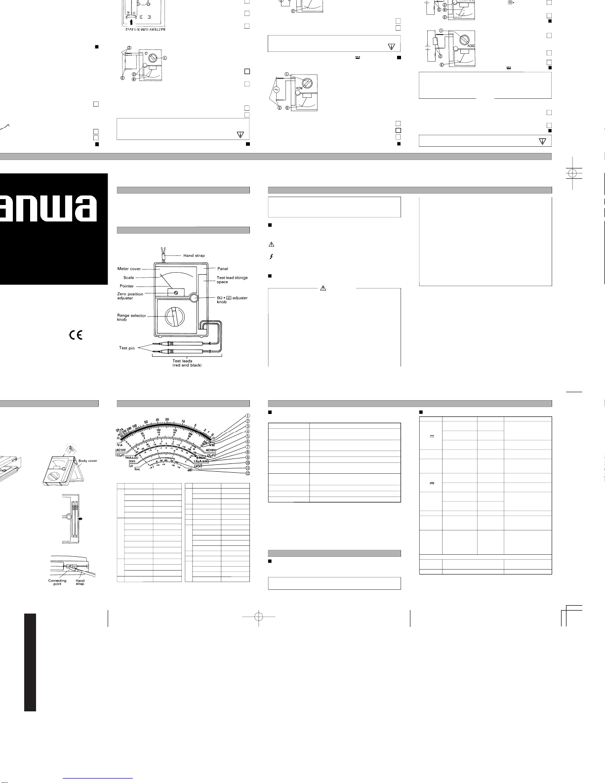
NAMES OF COMPONENTS
−1− − 2− − 3−
INTRODUCTION
Thank you for purchasing a SANWA tester Model YX360TRF. You are
kindly requested to thoroughly read this manual before use for safety.
Especially, “SAFETY INFORMATION” and “MEASURING PROCE-
DURE” are important. Keep this manual together with the tester so as
no to lose it.
Fig. 1
SAFETY INFORMATION
SPECIFICATIONS
The following are precautions to prevent accidents such as electrical
shocks.
Be sure to read them before using the tester.
Symbols
The following cautionary signs appear on the multitester and
in this manual.
Disobedience to instructions with this sign may lead to trouble
with the tester and accidents such as electrical shock.
This sign cautions that high voltage is applied to parts marked
with it.
Precautions for Safety Measurement
To ensure that the meter is used safely, follow all safety and operat-
ing instructions.
11. Never use the meter on the electric circuits that exceeds 3kVA.
12. Pay special attention when measuring the voltage of AC 33 Vrms
(46.7V peak) or DC 70V or more to avoid injury.
13. Never apply input signals exceeding the maximum rating input
value.
14. Never use the meter for measuring the line connected with equip-
ment (i.e. motors) that generates induced or surge voltage since it
may exceed the maximum allowable voltage.
15. Never use the meter if the meter or test leads are damaged or broken.
16. Never use an uncased meter.
17. Be sure to use a fuse of the specified rating or type. Never use a
substitute of the fuse or make a short circuit of the fuse.
18. Always keep your fingers behind the finger guards on the probe
when making measurements.
19. Be sure to disconnect the test pins from the circuit when changing
the function or range.
10. Before starting measurement, make sure that the function and
range are properly set in accordance with the measurement.
11. Never use the meter with wet hands or in a damp environment.
12. Never use test leads other than the specified type.
13. Never open the case except when replacing batteries or fuses. Do
not attempt any alteration of original specifications.
14. To ensure safety and maintain accuracy, calibrate and check the
meter at least once a year.
15. Indoor use only.
WARNING
− 5− − 6− − 7−
BODY COVER, TEST LEADS, HAND STRAP
Use of Cover (example for the body cover)
When this tester is out of use:
Attach the cover to the panel face for safekeeping.
When measuring:
Attach it either to the rear case side
or use it as a stand as shown below.
Storage of Test Leads
When placing the test leads in the
storage space, roll it 3 times, then
put in the test pin side first as shown
below.
Attachment of Hand Strap
1 Loosen the screws fixing the rear
case and remove it.
2 Hand strap is attached to con-
necting point.
3 Put back the rear case where it
was and fix it with the screws.
Fig. 2
− 4−
SCALE READING
Range Multiplied
1X 100k X 100k
1X1k X1k
1X 100 X 100
1X10 X10
1X1 X1
DCV 250 X 1
DCV 2.5 X 0.01
DCV 0.25 X 0.001
ACV 250 X 1
DCA 0.25 X 0.001
DCA 25m X 0.1
DCA 2.5m X 0.01
DCV 50 X 1
ACV 50 X 1
DCA 50 μ X 1
DCV 0.1 X 0.01
Range Multiplied
DCV 10 X 1
DCV 1000 X 100
ACV 750 X 100
ACV10 X 1
C (μF) X 1
DCV ± 25 X 1
DCV ± 5 X 1
150mA at X 1 X 10
15mA at X 10 X 1
1.5mA at X 100 X 0.1
150 μA at X 1k X 10
1.5 μA at X 100k X 0.1
LV X 1
h
FE
X1
ACV 10 X 1
ACV 50 14dB added
ACV 250 28dB added
ACV 750 40dB added
햻
햽
햾
General Specifications
(Temperature : 23±2˚C humidity 75% RH max. No condensation)
Drop shock proof A taut-band structure is adopted in the meter part.
The meter part is designed to withstand shock.
Circuit protection
The circuit is protected by fuse even when voltage of up
to AC 230V is impressed on each range for 5 seconds.
Internal battery
Internal fuse
R6 (IEC) or UM-3 1.5V X 2
F500mAH/250V Ø5.2 X 20mm Fast acting fuse
Operating temperature
and humidity range
5 ~ 31˚C, 80%RH max.
31< ~ 40˚C, 80 ~ 50%RH (decreasing linearly)
Withstand voltage
Dimensions and weight
6kV AC (1min.) between input terminal and case
159.5 X 129 X 41.5 mm/ approx. 320g
Storage temperature/
Humidity -10 ~ 50˚C 70%RH max. No condensation
Accessories Instruction manual 1, Hand strap 1,
Items Specification
Note: The definition of installation category,i.e.
CAT II : Local level, appliances, portable equipment etc.,
with smaller transient overvoltages than installation cate-
gory III.
CAT III : Distribution level, fixed installation, with smaller
transient overvoltages than installation category IV.
Application
This instrument is portable multitester designated for meas-
urement of weak current circuits.
The specifications described in this manual are subject to
change without notice.
Measurement Range and Accuracy
Function Full scale value Accuracy Remarks
0.25/2.5/10/50 ±3% against
full scale
APPLICATION
• HV probe, HV-10T • h
FE
probe, HFE-6T • Test lead for repair, TL-6IT
− 8− − 9− − 10− − 11−
MEASURING PROCEDURE
Measuring DCV
1 Set the range selector knob to
an appropriate DCV range.
2 Apply the black test pin to the
negative potential, and the red
test pin to the positive poten-
tial of the circuit.
3 Read the movement of the
pointer by V and A scale.
WARNING
Confirm the range of use before measurement.
Preparation for Measurement
1 Adjustment of meter zero position:
Turn the zero position adjuster so that the pointer may align
right to the zero position.
2 Range selection:
Select a proper range for the item to be measured and set
the range selector knob accordingly.
When determining a measuring range, select a one higher
voltage than the value to be measured as well as where the
pointer of a meter moves to a considerable extent.
However, select the maximum range and measure in case
the extent of value to be measured can not be predicted.
NOTE
Measuring ±DCV (NULL)
1 Set the range selector knob to
an appropriate ±DCV (NULL)
range.
2 Turn the 01adjuster so
that the pointer may align
exactly to 0 by ±DCV scale.
3 Apply the black test pin to the
negative potential side, and
the red test pin to the positive
potential side of the circuit.
4 Read the movement of the pointer by ±DCV scale.
Fig. 3
Measuring ACV 〜
1 Turn the range selector knob to an appropriate ACV range.
2 Apply the test leads to the circuit to be measured.
3 Read the movement of the pointer by V and A scale. (Use
AC 10V scale for 10V range only.)
• Since this instrument provides
the mean value system for its AC
voltage measurement circuit, AC
waveform other than sine wave
may cause an error.
• Errors occur under such frequen-
cies other than those in the speci-
fication table.
Measuring DCA
1 Turn the range selector knob to an appropriate DCA range.
2 Take out the circuit to be measured and apply the black test
pin to the negative potential,
and the red test pin to the
positive potential of the cir-
cuit.
3 Read the movement of the
pointer by V and A scale.
WARNING
Connect the meter in series with the load.
Cut off.
Fig. 4
Fig. 5
Measuring 1
1 Turn the range selector knob to an appropriate 1range.
2 Short the red and black test pins and turn the 01adjuster so
that the pointer may align exactly to 01. (If the pointer fails
to swing up to 01even when the 01adjuster is turned
clockwise fully, replace the internal battery with a fresh one.)
3 Apply the test pin to measur
resistance.
4 Read the movement of the point-
er by 1scale.
Note: The polarity of + and - is
reverse to that of the test
leads when measurement is
done in 1range.
Note: How to replace battery.
1 Loosen the screws fixing the rear
case and remove it.
2 Replace R6 (UM-3) to fresh dry
batterise.
3 Put back the rear case where it
was, and fix it with the screws.
Note:
Be sure to use the same rated
fuse. In case a fuse other than
the same rate (see “SPECIFICATIONS“) is used, an error in
indication occurs and/or circuit protection is made unable.
WARNING
Do not measure the resistance in a circuit where
a voltage is present.
Fig. 6
Fig. 7
Measuring Capacity (C)
1 Set the range selector knob to C(μF) .
2 Measure the capacitance by applying
the test pin to the capacitor to be meas-
ured after the 01adjustment is made
in the same manner as in the resist-
ance measurement.
3 The pointer moves full scale by the charge current to the
capacitor. However, the pointer gradually starts returning to its
original position. Read the indicated maximum value on C(μF)
scale.
Note: Be sure to short circuit the both ends of the capacitor for
discharge prior to the initial measurement or in such case
after the measurement is made.
Note: Pay due attention to the polarity (+ and -) of the capacitor.
(Connect + side of the capacitor to - side of the meter.)
Measuring AF Output (dB)
dB (decibel) is measured in the same way as the ACV
measurement, but by reading the dB scale instead.
For measurement on the 10V range, the dB scale (- 10dB ~
+22dB) is read directly, but, when measured on the 50V
range, 14dB is added. On the 250V range, 28dB is added to
the reading on the scale, and on the 1000V range, 40dB
added.
Thus, the maximum dB readable is 22 + 40 = 62 (dB) meas-
ured on the 1000V range.
Note: Cut direct current with a capacitor of 0.1μF or more when
measuring such signal as having direct current.
Fig. 8
− 12− − 13− − 14− − 15−
MEASURING PROCEDURE
Measuring of Iceo (Leak Current) for Transistor
1 Adjust 01by setting the range selector
knob to a proper range from X1 ~ X1k.
2 For NPN transistor, apply a black test
lead to the collector and a red one to
the emitter.
For PNP transistor, the red one to the col-
lector and the black one to the emitter.
3 Determine the leak current by ICEO
scale indicated on the scale plate. (Unit
in μA, mA)
Measuring of Diode (including LED)
1 Adjust 01by setting the range selector knob to a proper
range from X1 (150mA) ~ X100k (1.5μA).
2 Apply the black test lead to anode side and the red one to
cathode side when measuring IF (forward current). Apply
the black test lead to cathode side and the red one to anode
side when measuring IR (reverse current).
3 Read the indicated value by LI
scale. (The pointer moves to a
considerable extent for IF, and
little extent for IR)
4 The value indicated on LV scale
during the measurement is the
forward voltage of diode.
Fig. 9
Fig. 10
USAGE OF OPTIONAL PROBES
Usage of High Voltage Probe (HV-10T)
Up to DC 25kV of CRT anode voltage can be measured by
connecting optional HV-10T probe.
WARNING
• Keep the hand (finger) away from high voltage
power supply. Electric shock may occur due to dis-
charge.
• Measurement should be limited only to micro cur-
rent circuits.
1 Turn the range selector knob and set it to HV PROBE (DC
2.5V range).
2 Connect the jack of the black lead of the probe to the black
test pin, and the jack of the red lead to the red test pin.
3 Apply the probe clip to the earth side and the measuring pin
to the point to be measured.
4 Read out measured value on 0 ~ 250 of V scale in kV unit
after multiplying it by 0.1.
Usage of h
FE
PROBE (HFE-6T)
1 Set the range selector knob to X10 range ( h
FE
PROBE).
2 Short circuit both the red and black test pins to adjust 01.
3 Connect the black test pin to the probe jack when a transis-
tor to be measured is NPN, and the red pin to the probe
jack for PNP transistor.
4 Connect the black clip of the probe to the transistor base
and the red clip to the collector.
5 Connect the remaining test lead to the emitter and measure
h
FE
.
6 Read the indicated value of the meter on h
FE
scale.
MAINTENANCE
How to Replace the Fuse
If voltage over 100V is applied
to DCA and 1ranges, the fuse
may blow out to protect the
circuit.
1 Loosen the screws fixing the
rear case and remove it.
2 Pull the fuse out of holder on the
circuit board and replace it.(Fig. 11)
3 Put back the rear case where it was and tighten the screws.
4 Check and see whether or not indications of respective
ranges are normal (check other parts for any failures).
Storage and Other Precautions
1 Avoid giving the meter any excessive shock or vibration by
loading it on the motorbike, for instance.
2 Keep off dust and moisture from the meter.
3 Do not leave the meter for a long time in places of a high
temperature (higher than 55˚C), a high humidity (higher than
80%), and dew condensation.
4 The meter cover is treated with antistatic coating. Do not
wipe it hard or clean it with volatile solvent. Use a soft
brush to remove dust.
Fig. 11
AFTER - SALES SERVICE
Warranty and Provision
Under Sanwa's general warranty policy, each instrument is war-
ranted to be free from defects in workmanship or material
under normal use for the period of one (1) year from the date of
purchase.
This warranty policy is valid within the country of purchase only,
and applied only to the product purchased from Sanwa author-
ized agent or distributor.
This warranty does not apply to fuses, disposables batteries, or
any product or parts, which have been subject to one of the fol-
lowing causes:
1. A failure due to improper handling or use that deviates
the instruction manual.
2. A failure due to inadequate repair or modification by peo-
ple other than Sanwa service personnel.
3. A failure due to causes not attributable to this product
such as fire, flood and other natural disaster.
4. Non-operation due to a discharged battery.
5. A failure or damage due to transportation, relocation or
dropping after the purchase.
Repair
Please contact Sanwa authorized agent/distributor/service
provider, listed in our website, in your country with your
information.
SANWA web site
http://www.sanwa-meter.co.jp