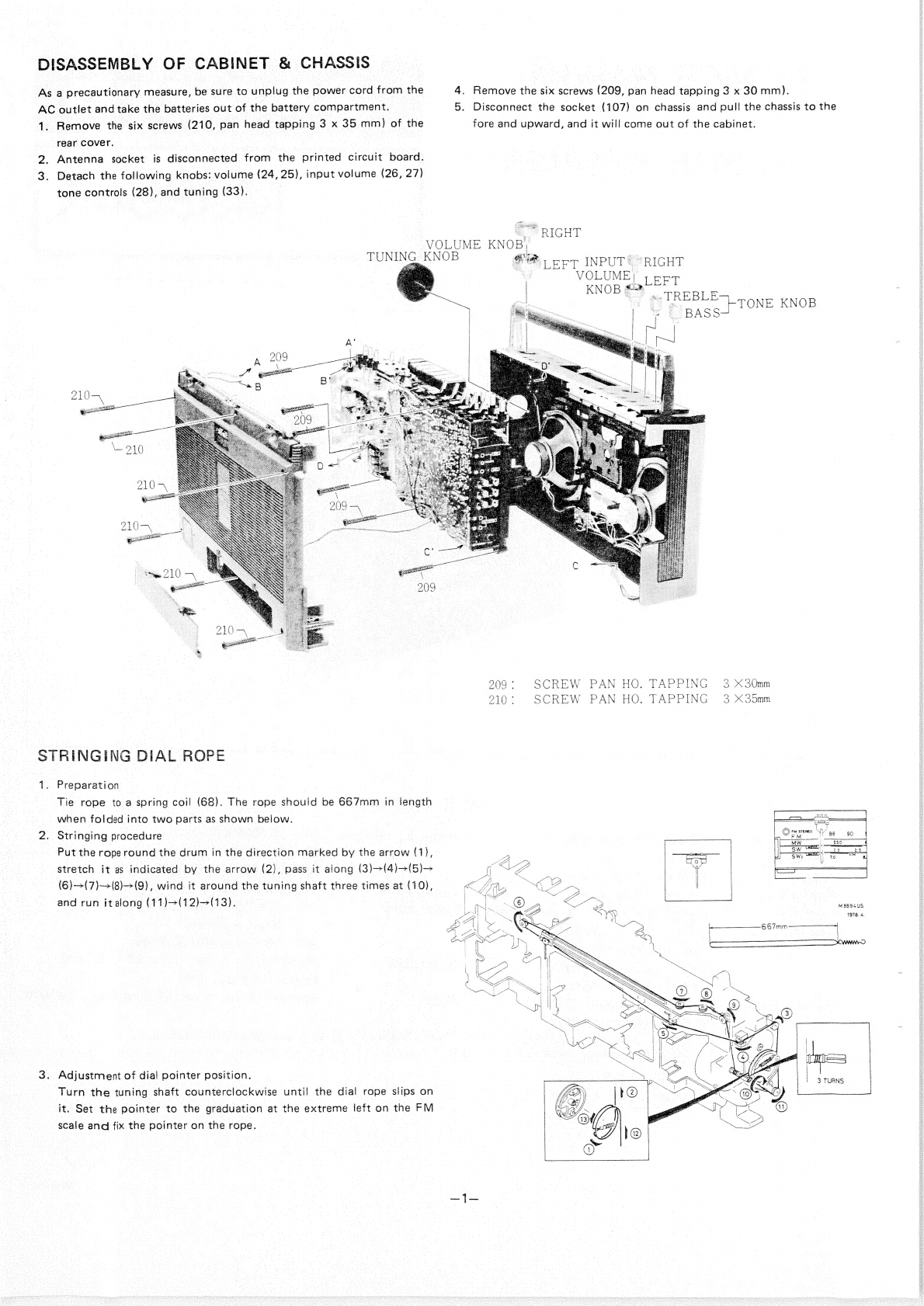
Sanyo M9994K User manual

SERVICE
MANUAL
CASSETTE
RECORDER
,
Recording
system
Erasing
system
Tape
speed
Rewind
and
fast
forwardtime
Frequency
range
Terminal
impedance
PHONO:
50k
ohms
(3mV)
SPECIFICATIONS
|
|
AC
bias,
4
tracks
stereo
|
Frequency
response
—
ACerase
|
=
1-7/8
i.p.s.
(4.75
cm/s)
| |
rae
~
Rewind:
2
min.
(C—60)
a
ae
Output
power
»
Fast
forward:
2
min.
20
sec.
(C—60)
Power
source
-
FM:
87.5
—
108
MHz
AM:
530
—
1605
kHz
_
:
-
‘SWI:
23-—7.0MHz
©
Dimensions
SSW
EOS
OZER
ea
oS
EXT.
MIC:
5k
ohms
(0.3mV)
ss
Weight
50
—
15,000Hz
(CrO,)
50
—
15,000Hz
(FeCr)
60
—
14,000Hz
(NORMAL)
7W
x
2
maximum
DC:
12V
“D”
(UM—1)
x
8
12V
Car
battery
AC:
120/200/240V
50/60Hz
20-3/8"'
(W)
x
5-1/4”
(D)
x
12-1/16"
(H)
(516
x
131
x
306
mm)
Approx.
16
Ibs.
12
ozs.
(7.6
kg)
including
batte
ae
LINE
IN:
180k
ohms
(6GOmV)
|
*
Specifications
subject
to
change
without
notice.
LINE
OUT:
1k
ohms
(0.7V)
|
ca
a
EXT
SP:2.5—8o0hms
—
_
HEADPHONES:
8
ohms
WM
-322

DISASSEMBLY
OF
CABINET
&
CHASSIS
As
a
precautionary
measure,
be
sure
to
unplug
the
power
cord
from
the
4.
Remove
the
six
screws
(209,
pan
head
tapping
3
x
30
mm).
AC
outlet
and
take
the
batteries
out
of
the
battery
compartment.
5.
Disconnect
the
socket
(107)
on
chassis
and
pull
the
chassis
to
the
1.
Remove
the
six
screws
(210,
pan
head
tapping
3
x
35
mm)
of
the
fore
and
upward,
and
it
will
come
out
of
the
cabinet.
rear
cover.
2.
Antenna
socket
is
disconnected
from
the
printed
circuit
board.
3.
Detach
the
following
knobs:
volume
(24,
25),
input
volume
(26,
27)
tone
controls
(28),
and
tuning
(33).
PRIGHT
VOLUME
KNOB)
TUNING
KNOB
ak:
x
@'®
cep
INPUT®
“RIGHT
:
VOLUME)
Ly
LEFT
KNOB
ss
‘
:
ey
Me
TREBLE
cone
KNOB
__
BASSH
209:
SCREW
PAN
HO.
TAPPING
3
30mm
210:
SCREW
PAN
HO.
TAPPING)
3
X35mm
STRINGING
DIAL
ROPE
1.
Preparation
Tie
rope
to
a
spring
coil
(68).
The
rope
should
be
667mm
in
Jength
when
folded
into
two
parts
as
shown
below.
2.
Stringing
procedure
Put
the
rope
round
the
drum
in
the
direction
marked
by
the
arrow
(1),
stretch
it
as
indicated
by
the
arrow
(2),
pass
it
along
(3)-(4)-(5)>
(6)—>(7)-+(8)(9),
wind
it
around
the
tuning
shaft
three
times
at
(10),
and
run
italong
(11)~(12)-(13).
M9S94US
1978.
4,
3.
Adjustment
of
dial
pointer
position.
Turn
the
tuning
shaft
counterclockwise
until
the
dial
rope
slips
on
it.
Set
the
pointer
to
the
graduation
at
the
extreme
ieft
on
the
FM
scale
and
fix
the
pointer
on
the
rope.
3
TURNS
ech
eee
neteer
Pee
enna
Ei
|

x
eee
ne
MODIFICATION
NOTICE
CASSETTE
RECORDER
M9994K
(USA)
M9994K
(AUSTRALIA)
M9994K
Date
June
20,
1979
Issued
by
ee
The
following
corrections
should
be
made
in
the
SERVICE
MANUALS
and
PARTS
(PRICE)
LIST.
Concerning
M9994
Series,
the
IC801,
901
used
in
AMP
PCB
assembly
has
been
modified
as
illustrated
below
in
the
midst
of
production.
Accordingly,
the
capacitance
and
resistance
of
neighboring
parts
and
wiring
are
also
changed.
Since
the
Serial
No.
at
the
time
of
modification
is
not
identified,
please
check
the
pertinent
IC
of
each
set,
and
modify
the
circuit
when
replacing
the
IC
if
necessary.
Ic801,
901
BAS
21
IC
BAS
32
os
©
n
© =
Ae)
=
3
ry
I
|
|
|
I
| | | I
| |
|
|
|
a
RA
R837,
937
3902
——*
Carbon
2702
#10%
zw
R839,
939
8.2K.
—_—-------
C832,
932
220uF
——
Electrolytic
4/pF
10V
G933,-993
C8394.
935
560pF
——>
Ceramic
270pF
110%
50V
C836,
936
C863,
963
0.0047UF—
-------
C899;.995°
===
——
Ceramic
220pF
+10%
50V
sie
sutures
kepbS
ee
RSS
ett
Aen
EAR
ai
a
Sey.
Sep
oh
A
a
a
aaah
veto
i
BSR
OR
a
REHEAT
PES
SSIES
SA
SERRE
ROP UES
RATAN
ED
SBR
BADE
NRE
STB
RE
REE
BE
ea
ES
x
3
:
INTERCHANGEABLE
NOT
INTERCHANGEABLE
Serial
No.
Effective
from
Q'ty
of
initial
production
before
modification.
|
Identification
of
modified
unit.
REASON
FOR
MODIFICATION
ie
SU
idles
ap
nae
aaa
a
US
ss
Aa
ene
ad
Reena
A
oe
Standardization
©
tna
improvement
of
reliability
EB
.
suas's
Miss print
G
...
Bou...
Change
of
materials
OD.
.....
Improvement
of
performance
F
.....
Miss
register
SANYO
ELECTRIC
TRADING
CO.,
LTD.
WM-
4153
Printed
in
Japan
S000
OSAKA,
JAPAN

cud
tanto
tHE
EUROS:
C832
C833
220p
0.1
ee
47/10V
R840
1K
a
R840
1K
R841
82K
RB41
82K
sac
Set
cals
aici
Se
Sih
$s
TN
SRE
St
To
ae
RA
AUER
eg
BE
Ba
ee
Bg
Ee
Se
Oe
oe
ee
eae
eee
EE
eR
Ec
ae
cette
ee
abs
Spanier
Told
fi
eRe
SR
Bx
SS
En
BEG
S
eo
Bits
IE
ERLE
SREB
ERE
GHEE
GIS
Bis
LETRA
BY
SEEDS
ii
SED
RR
SIEBOT
et
Ea
REO
ace
a
Retaseb
NAS
a
Tce
ech

enone
ctv
Ri
cians
TORQUE
ADJUSTMENT
TAPE
SPEED
ADJUSTMENT
1.
Set
the
unit
to
the
PLAY,
FAST.FORWARD
or
REWIND
mode.
1.
Connect
a
frequency
counter
to
the
Ext.
Speaker
jack.
2.
Measure
the
each
torque
with
a
torque
gauge.
They
should
be
as
2.
Mount
a
3
kHz
test
tape
on
the
unit
and
play
it
back.
Turn
tl
following;
potentiometer
inside
the
motor
and
adjust
it
until
the
counter
rea
PLAY
35
—
60
g/cm
ing
becomes
2970~3020Hz.
FAST
FORWARD
60
—
100
g/cm
REWIND
65
—
100
g/cm
3.
If
the
each
torque
fails
to
reach
the
standard
value.
Clean
the
drive
HEAD
AZIMUTH
ADJUSTMENT
belt,
flywheel,
motor
pulley,
take-up
reel,
idler
and
rewind
roller
1.
Mount
a
music
tape
on
the
unit
for
the
reproduction
of
tape.
Inse
with
a
cotton
swab
soaked
in
alcohol.
the
screw
driver
(+)
to
azimuth
hole,
and
turn
the
azimuth
adjusti!
screw
until
to
the
maximum
sound.
PINCH
ROLLER
ADJUSTMENT
1.
Set
the
unit
the
Play
mode.
2.
Apply
a
tension
gauge
(500
gr)
to
the
pinch
roller
and
measure
the
pressure.
The
gauge
reading
should
be
within
the
range
300
—
400
gr.
3.
To
adjust
the
contact
pressure,
bend
the
spring
or
change
the
spring
with
a
new
one,
if
necessary.
ADJUSTMENT
OF
STAND-BY
MECHANISM
(RESULTANT
FORCE
OF
LOCK-LEVER
SYSTEM)
The
lever
of
the
slide
(445)
has
to
be
unlocked
with
the
revolving
shaft
of
the
pulley
(443)
kicking
it
before
the
stand-by
mechanism
works.
Employ
a
spring
gauge
capable
of
measuring
a
force
of
up
to
110
g
for
making
this
adjustment.
Resultant
force
of
lock-lever
system
.....
100g
or
smaller
In
the
event
that
the
resultant
force
is
larger
than
the
above
specification,
adjust
by
bending
or
replace
the
spring
coil
331
(141-2-851T-56100).
j
‘
;
;
i
i
'
a
‘
4
4
{
|
|
:
:
j
;
4

AUTO
STOP
MECHANISM
(Read
this
section
in
reference
to
the
mechanical
exploded
view
on
Page
14
&
15)
Theory
of
operation
When
the
end
of
tape
has
been
reached
in
the
REC
or
PLAY
mode,
the
PLAY
button
is
unlocked
and
operation
stops
automatically.
1.
Auto
stop
and
worm
gears
(3)
(4)
keep
revolving
while
the
motor
is
running.
FLYWHEEL
(1)
GEAR
(3)
\
———-
WARM
GEAR
(4)
2.
While
the
tape
is
running
1)
Take-up
reel
(7)
causes
relay
gear
(6)
to
turn.
Auto
stop
pulley
mounted
on
the
shaft
of
relay
gear
(6)
also
turns
in
the
sarne
direction.
2)
While
flywheel
(1}
is
turning,
it
keeps
the
rear
end
of
auto
stop
slide
(9)
moving
on
the
cam
of
auto
stop
gear
(3).
Therefore,
it
does
not
become
engaged
with
hook
(5)
on
auto
stop
pulley
(8),
so
the
auto
stop
mechanism
does
not
work.
3.
When
the
tape
end
has
been
reached
1)
Take-up
reel
stops
revo!ving.
So
does
the
rear
end
of
auto
stop
slide
(9).
2)
Hook
(5)
on
auto
stop
pulley
(8)
catches
the
rear
end
of
auto
stop
slide
(9)
which
is
pulled
toward
the
motor,
unlocking
the
PLAY
button.
AUTO
STOP
PULLEY
HOOK
(5)
AUTO
STOP
GEAR
(3)
/
RELAY
SCENES)
ee
cue
\\
Bey
!
|
AUTO
STO
PULLEY
(8)
=a)
jap
are
STOP
SLIDE
(9)
4.
When
the
PAUSE
button
is
locked
Auto
stop
pause
spring
(12)
keeps
pushing
the
rear
end
of
auto
stop
slide
(9)
against
the
cam
of
auto
stop
geat
(3).
Accordingly,
the
rear
end
of
auto
stop
slide
(9)
moves
on
the
cam
and
remains
out
of
reach
of
hook
(5)
on
auto
stop
pulley
(8).
Thus,
the
auto
stop
mechanism
does
not
work.
I
AUTO
STOP
|
SL
IDE
(9)—e
AUTO
STOP
LEVER
(10)
|
|
|
|
_
AUTO
STOP
PAUSE
SPRING
(12)
—
O
eo——
PAUSE
BOTTON
(13)
despa
aR
nt
ihe
EAB
arbi
Rings
seats,
BRD
Lieb
RAE
REET
SERED
tS
ARBAB
ESS

snag
vg
fe
Seth
ann
eaP
SRE
Sokelnniea
ADJUSTMENT
OF
AMPLIFIER
SECTION
ADJUSTMENT
OF
RECORDING
GAIN
ADJUSTMENT
OF
PLAYBACK
GAIN
Playback
test
tape
(1kHz,
OdB)
and
adjust
SVR701
(50KB)
to
equalize
outputs
at
LINE
OUTs
for
the
left
and
right
channels.
Conditions:
Automatic
level
control
(ALC)
+
ON
PREPARATION
Volume
controls
(VOLUME)
+
MIN.
|
All
necessary
adjustments
should
be
made
at
a
source
power
voltage
of
Mode
selector
(MODE)
~
STEREO
:
DC12V.
insert
blank
tape,
set
the
unit
in
the
recording
mode
and
apply
1kHz—
Turn
the
TONE
controls
(BASS
and
TREBLE)
to
their
center
positions
25dB
(S5mV)
signal
to
the
LINE
IN
jacks.
|
and
the
INPUT
VOLUME
controls
(left
and
right
channels)
to
their
Connect
a
VTVM
to
the
collectors
of
Q807
and
Q907
and
adjust
SVR
maximum
settings.
702
until
left-
and
right-channel
outputs
become
identical.
The
settings
of
other
controls
are
as
follows:
Function
switch
(FUNCTION
1)
+
TAPE
Input
line
switch
(FUNCTION
2)
>
LINE
Tape
selector
(TAPE)
-
NORMAL
ADJUSTMENT
OF
METERS
Conditions:
Automatic
level
control
(ALC)
—
ON
Mode
selector
(MODE)
-~
STEREO
Playback
test
tape
(1kHz,
OdB)
and
turn
the
volume
control
(VOLUME)
until
the
reading
of
the
meter
for
the
right
channel
becomes
2W
(OVU).
Adjust
SVR703
until
the
meter
readings
for
the
left
and
right
channels
become
identical.
TEST
TAPE
ADJUSTMENT
OF
ALC
Conditions:
Automatic
level
control
(ALC)
—
ON
Volume
controls
(VOLUME)
—
MIN.
Mode
selector
(MODE)
—
STEREO
|
After
finishing
with
adjusting
the
recording
gain
as
instructed
in
(4
above,
insert
blank
tape,
set
the
unit
in
the
recording
mode,
and
appl)
1kHz—5dB
(1.7V)
signal
to
the
LINE
IN
jacks.
Connect
a
VTVM
to
the
collectors
of
Q807
and
Q907.
Adjust
SVR70:
to
obtain
identical
outputs
from
the
left
and
right
channels.
SVR
701
¢
SVR
702
©
SVR
703
|
METER
ADJ
ADJUSTMENT
OF
BIASES
Mount
blank
tape
and
set
the
unit
in
the
recording
mode,
while
connect-
ing
a
VTVM
to
the
10-ohm
terminals
of
R845
and
R945.
Adjust
SVR801
and
SVR901
until
the
VTVM
stands
at
3.5mV.

ADJUSTMENT
OF
TUNER
SECTION
ADJUSTMENT
OF
TUNING
METER
Supply
98MHz,
80dB
(10mV)
signal
from
an
FM
signal
generator
to
the
unit
at
TP1
(HOT
side)
and
TP2
(GROUND
side),
tune
the
unit
to
the
receiving
frequency
and
adjust
SVR301
so
the
meter
needle
points
to
9.5.
FM
SIGNAL
GENERATOR
OL)
O
Roa
O
G
=i
TUNING
"6
>
KS
Cyseits
fy
SS
il
“SVR301
[ey
~S_
oA
ADJUSTMENT
OF
FM
MULTIPLEX
(1)
Set
SVR501
(10KB)
to
its
center
position.
(2)
Adjust
the
modulation
of
the
FM
signal
generator,
using
a
stereo
modulator.
*Modulation
frequency
=
400Hz
Pilot
signal
7.5kHz
dev.
(10%
modulation)
Stereo
signal
Main
signal
22.5kHz
dev.
(30%
modulation)
NOTE:
Adjustment
of
modulation
varies
according
to
the
type
of
instru-
ment
in
use.
You
are
encouraged
to
know
fully
well
the
operation
of
the
instrument
you
are
employing.
STEREO
MODULATOR
+
|MPX
OUTPUT
FM
SIGNAL
GENERATOR
FREQUENCY
COUNTER
(3)
Connect
an
IHF
filter
(200~15kHz)
to
the
left-channel
LINE
OUT.
Connect
the
filter
toa
VTVM.
(4)
Set
the
output
signal
switch
of
the
stereo
modulator
to
MAIN
(L+R).
Set
the
unit
to
receive
a
radio
frequency
of
98MHz
and
tune,
using
the
FM
signal
generator.
(5)
19kHz
adjustment
(VCO
adjustment)
Set
the
radio
unit
so
there
is
no
input
in
the
FM
stereo
mode.
Con-
nect
a
frequency
counter
to
TP3
and
make
necessary
adjustment
by
means
of
SVR501
(10KB)’so
that
the
counter
reading
becomes
19kHz
+
100Hz.
*HOT
side
of
frequency
counter:
TP3
GROUND
side
(E):
shield
case
(6)
Separation
adjustment
1)
Connect
a
300-ohm
dummy
load
to
an
FM
signal
generator
and
the
dummy
load
to
the
unit,
to
TP1
on
the
HOT
side
and
to
TP2
on
the
GROUND
side.
Set
the
output
signal
switch
of
the
stereo
modulator
to
MAIN
(as
in
Section
(4)
above)
and
supply
pilot
signal.
Set
the
BASS
and
TREBLE
controls
to
their
center
positions
and
regulate
the
stereo
signal
input
to
66dB.
Then,
reduce
the
distortion
factor
to
a
minimum
by
tuning,
using
the
radio
tuning
control
or
by
means
of
the
FM
signal
generator.
Adjustment
of
left-channel
separation
Set
the
output
signal
switch
to
RIGHT
and
minimize
leakage
of
right-channel
signal
into
the
left
channel
by
adjusting
SVR502
(500B).
Adjustment
of
right-channel
separation
Reconnect
the
cord
from
the
IHF
filter
from
the
LEFT
to
RIGHT
LINE
OUT
jacks,
set
the
output
signal
switch
to
LEFT
and
minimize
leakage
of
left-channel
signal
into
the
right
channel
by
adjusting
SVR502
(500B).
In
case
the
minimum
signal
leakage
positions
of
SVR502
adjusted
as
instructed
in
Sections
(4)
and
(5)
differ
from
each
other,
determine
its
optimum
position
within
a
range
that
satisfies
the
specified
separation
value
(20dB
or
higher)
for
each
of
the
two
channels.
*
In
the
above-described
steps
of
adjustment,
tuner
output
is
taken
out
at
LINE
OUT.
The
IHF
filter
(BANDPASS
200~
15000Hz)
can
be
dispensed
with
when
connections
are
made
to
EXT-SP.
2
—
3
—
4
—
5
~——_
6
—
DISTORTION
IHF
FILTER
ASS
os

MW
ADJUSTMENT
Leet.
455
KHz
Low
end
of
dial
scale.
(400
Hz
30%
|
At
position
of
un-
a
MAX.
modulation)
required
signal.
505
KHz
(400
Hz
;
30%
modulation)
Low
end
of
dial
scale
L112
MAX.
1650
KHz
(400
Hz}
,,.
:
30%
modulation)
High
end
of
dial
scale
600
KHz
(400
Hz
:
30%
modulation)
600
KHz
on
dial
scale
L109b
MAX.
1400
KHz
(400
Hz
:
30%
modulation)
1400
KHz
on
dial
scale
PREPARE:
1.
Set
the
dial
pointer
to
very
left
line
of
dial
scale.
3.
Selector
switch
to
“MW”.
2.
Connect
sweep
generator,
AM
SG,
VTVM
and
oscilloscope.
4.
Use
a
screwdriver
with
plastic
grip
for
all
adjustments.
geist
J
T301,
T302
XB
T303
-
75
kerta,
87.0
MHz
(400
Hz
§
dial
scal
30%
modulation)
Rowing
Onelelscae
L107
MAX.
109.0
MHz
(400
Hzj,,.
:
40%
macdulation]
High
end
of
dial
scale
90.0
MHz
(400
Hz
:
30%
modulation)
90.0
MHz
on
dial
scale
L105
-
x.
106.0
MHz
(400
Hz
;
30%
modulation)
106.0
MHz
on
dial
scale}
CT1
Connect
sweep
Connect
oscillo-
generator
to
scope
to
EXT.
SP
Test
Loop.
terminals
Connect
AM
SG
to
Test
Loop.
Connect
VTVM
to
speaker
terminals.
Connect
AM
SG
to
Test
Loop
Connect
VTVM
to
speaker
terminals.
FM
ADJUSTMENT
Adjusting
Circuit
0.S.C.
VTVM
Oscilloscope
SG
frequency
Position
of
tuning
dial
Connect
oscillo-
scope
to
test
point
TP6,
R319(H)
Shield
cast
(E)
Connect
sweep
generator
to
FM
TP1
(H)
&
TP2
(E)
Near
max.
capacity
of
VC.
at
position
with
unrequired
signal.
10.7
MHz
(0%
modulation)
Connect
oscillo-
scope
to
test
point
TP7,
R324(H)
Shield
case
(E)
Connect
FM
SG
to
TP1(H)
&
TP2
(E)
Connect
VTVM
to
speaker
terminal.
Connect
FM
SG
to
TP1
(H)
TP2
(E)
Connect
VTVM
to
speaker
terminal.
-
_
7
Repeat
adjustments.
PREPARE:
1.
Set the
dial
pointer
to
very
left
line
of
dial
scale.
112.5
ohm
2.
Connect
sweep
generator,
FM
SG,
VTVM
and
oscilloscope.
FM
antenna
input
impedance
is
300
ohm.
e
3.
Use
a
screwdriver
with
plastic
grip
for
all
adjustments.
§
4.
AFC
switch
OFF.
Te)
*
Because
an
AFC
is
incorporated,
FM
tracking
and
frequency
coverage
adjustments
have
to
be
made.
5
Use
a
small
input
(about
10dB)
for
this
purpose.
150
ohm
SW1
ADJUSTMENT
Aajuating
Cireuit™
[Tope
|
Outout
|
1
2,2
MHz
(400
Hz
;
30%
modulation)
Low
end
of
dial
scale
L111
pm
Connect
AM
SG
Connect
VTVM
to
tat
ose
to
Test
Loop.
speaker
terminals.
2
7.2
MHz
(400
Hz
|
,,.
30%
modulation)
|
High
end
of
dial
scale
CT6
2.5
MHz
(400
Hz
.
30%
modulation)
2.5MHz
on
dial
scale
L109a
6.5
MHz
(400
Hz
;
30%
modulation)
6.5MHz
on
dial
scale
fe
ec
Repeat
adjustments.
PREPARE:
1.
Set
the
dial
pointer
to
very
left
line
of
dial
scale.
3.
Selector
switch
to
‘‘SW1”.
2.
Connect
sweep
generator,
AM
SG,
VTVM
and
oscilloscope.
4.
Use
a
screwdriver
with
plastic
grip
for
all
adjustments.
5.
Set
the
Fine
Tuning
to
mechanical
center.
Connect
AM
SG
to
Test
Loop.
Connect
VTVM
to
speaker
terminals.
ea
a“
SW2
ADJUSTMENT
Adjusting
Se.
ee
ace
Circuit
[Input
[Output
|
_S@ereavency
|
Postion
of
tuning
diel
|
Adlurment
|
oscilloscope
OSC
at
_
COME
Genin
Connect
VTVM
to
iain
erage
ee
eon
tgefe
High
end
of
dial
scale.
CTs
Sa
i
eel
21.0MHz
on
dial
scale.
Connect
AM
SG
to
ANT
terminal
through
IRE
dummy.
Connect
VTVM
to
EXT.
SP.
terminals.
Repeat
adjustments.
PREPARE:
1.
Set
the
dial
pointer
to
very
left
line
dial
scale.
4.
Selector
switch
to
‘““SW2”’.
-—O
2.
Connect
signal
generator
to
dummy
antenna.
5.
Set
the
Fine
Tuning
to
mechanical
center.
10pF
3.
Use
screwdriver
with
plastic
grip
for
all
adjustments.
6.
Use
a
Dummy
antenna
as
follow.
50
ohm
fer
eae
1
sie
ent
ASE
AE
ORE
I
TESA
iB
Ras
sapBSB
AEA
AEET
EIS
aR
i
:
i
i
;
4
‘
‘
!
3
x
H
}
;
4
4
i
4
i
4
|

EXPLODED
VIEW
‘
i
i
mw
FA
SS.
LE
P
J
7
:
°
“\
eee
A
—
5
.
.
.
Piste
y/7a8
&
y
.
/
.
.
4
WW
y
¥
:
\,
+,
-
/
¢
av
fv
4
y
ae//
ta
f
y
“\y
K
J
/
Qf
ft
f
/
J
MU
[fv
f
fi
fh
;
fy
]
f
i
4
/
y
i
“7
—_
i
4

PARTS
LIST
PACKING
141
6
132T
90400
141
6
410T
14100
141
6
144T
47100
141
6
144T
47200.
141
6
231T
55700
141
6
231T
20350
141
6
231T
20300
141
6
231T
10200
141
0
385T
02900
141
6
132T
90300
individual
Carton,
Set
Instruction
Book
Foam
Plastic
Case
Foam
Plastic
Case
inner
Polye
Cover,
Set
inner
Polye
Cover,
Inst
B
inner
Polye
Cover,
Mic
Inner
Polye
Cover,
Mic
Stand
Bracket
Mic
Assy
Individual
Carton,
Mic
—
=
—
=
A) A)
A)
@ = @
a2
=
=
141
6
316T
98800
|
Pad,
Top
141
6
316T
99000
|
Pad,
Handle
141
2
171T
09500
|
Handle
ACCESSORIES
4
243T
13001
|
Power
Cord
4
243T
76401
Power
Cord
a
,
4
243T
79100
|
Power
Cord
4
243T
11500
|
Power
Cord}
4
241T
12671
4
153T
10700
Cassette
Tape
C-12
Microphone,
without
Remote
4
153T
10800
Microphone,
with
Remote
4
236T
11201
Plug
Assy
CABINET
|
141
01117
35001
|
Cabinet
Assy
141
2
131T
16000
|
Clear
Window
141
2
210T
07300
|
Bracket
141
0117T
04200
|
Speaker
Box
Assy
(141-9-117T-00300)
Escutcheon
Lug
Shield
Plate
Cushion
Bracket
Washer
3x12x1,
Fiber
Gear
Assy
(141
0
581T
01200)
Lug
Back
Lid
Assy
Lug
Battery
Lid
Assy
(141
9
128T
04101)
Top
Lid
Assy
Spring
Coil
Shaft
Handle
Assy
(141
0
171T
08800)
Bracket,
Handle
Cushion,
VU
Meter
Lever
Bracket,
Mater
Rotary
Knob,
Main
VR,
Upper
Rotary
Knob,
Main
VR,
Lower
Rotary
Knob,
Input
VR,
Upper
Rotary
Knob,
Input
VR,
Lower
Rotary
Knob,
Tone
Lever
Knob
Assy
Push
Button
Assy,
Power
Push
Button
Assy,
Band
Push
Button
Assy,
Editer
Rotary
Knob,
Tuning
Rotary
Knob,
Fine
Tuning
Sign
Window,
Voltage
Select
emo
mh
eh
eed
141
2
153T
40200
123
2
472R
00601
141
2
322T
45500
141
2
447T
46200
141
2
210T
09000
141
2
453T
01000
141
0
581T
10900
123
2
472R
00401
141
0
126T
23602
123
2
472R
11100
141
0
128T
12300
onmwoo
HBWNH—
NA]
=
PNW
—NNND
h-=-
141
0
124T
20201
141
2
855T
06200
141
2
751T
39900
1410171T
13700
141
2
271T
14600
141
2
447T
65000
141
2
742T
10500
141
2
373T
06200
141
2
163T
49400
141
2
163T
49500
141
2
163T
49600
141
2
163T
49700
141
2
163T
49800
141
0
162T
14000
141
0
161T
51701
141
0
161T
51700
141
0
161T
51800
141
2
163T
50400
141
2
163T
53200
141
2
132T
03800
2
2 2
od
A
OTA)
Be
ND
AM
ANA
CHASSIS
141
2
363T
07200
141
2
742T
15000
123
2
566R
12000
141
0
311T
28200
141
0
146T
16802
141
2
245T
05000
141
2
446T
06600
141
2
453T
30500
141
2
566T
07400
Bracket,
VC
Lever,
Rec
Tuning
Shaft
Chassis
Assy
(141
9
311T
07000)
Dial
Scale
Assy
Back
Plate
Plastics
Cushion,
Tuning
Meter
Washer
4.1x6.5x0.13,
Nylon
Tuning
Shaft
pak
ee ee ee ee
ee
ee
CHASSIS
141
2
573T
08400
141
2
521T
01900
141
0
210T
07600
141
2
538T
08900
141
2
581T
11000
141
2
581T
11100
141
0
511T
13300
141
2
851T
06300
141
2
855T
26100
141
2
340T
00200
141
2
361T
14100
141
2
361T
14200:
141
2
385T
02200
141
2
853T
55400
|
123
2
566R
12000
|
Tuning
Shaft
141
2
453T
31701
|
Washer
4x8x0.5
Nylon
141
2
472T
07300
|
Lug
141
2
472T
07200
|
Lug
141
2
447T
45501
|
Cushion,
Tuning
Meter
141
2
447T
16200
|
Cushion
Bracket,
Tuning
Shaft
Fiywheel
Bracket
Assy,
Drum
Drum
Gear
Gear
Spring
Coil,
Rope
Spring
Coil,
Gear
Rope
Bracket
Resistor,
Main
VR
Bracket
Resistor,
Input
VR
Bracket,
‘Mic
Spring
Plate,
Rec
ELECTRICAL
PARTS
4
231T
76220
4
231T
75020
4
151T
27200
4
151T
17873
4
511T
09200
4
511T
09300
4
235T
56200
4
222T
64600
4
251T
84000
4
153T
10500
4
231T
53720
4
231T
74920
4
612T
10874
_
Switch,
Power
Switch,
Dial
Light
Speaker
16cm
Speaker
5cm
Tweeter
Meter,
Tuning
/
Battery
Meter
VU/Watt
Socket
9P
Variable
Resistor
10K-A,
Input
Power
Trans
Microphone
Switch,
Edigi
Switch,
Mix
Pilot
Lamp
9V
100mA
Electrolytic
Cap.
4.7uF
25V
Nonpolar
(C839,
939)
Socket,
Voltage
Select
Terminal,
Voltage
Select
Plug
Assy,
Voltage
Select
Socket,
Ant
Telescopic
Rod
Ant
Terminal
Board
Ceramic
Cap.
10pF
50V
+
10%
(C117,
118)
RF
Choke
Terminal
Board
Fine
Tuning
Lead
Lead
Antenna
Coil,
MW
SW1
4
235T
33200
141
2
382T
03100
4
236T
09902
4
235T
34600
4
244T
03100
4
237T
07800
4
253R
11160
4
237T
05800
4
224R
20700
4
243T
12801
4
243T
12802
4
257T
27901
AMP
PCB
ASSY
140
4
230T
55972
4
231T
74300
4
231T
74400
4
231T
74500
4
231T
74600
4
231T
74700
4
235T
53400
2
464T
30300
4
231T
65200
4
222T
39578
115
P.C.
Board
Assy,
AMP
Switch,
Mono-Stereo-Wide
Switch,
FE-FEcr-CRo2
Switch,
Tape-Radio-Phone
Switch,
Rec-Play
Switch,
ALC,
Mic-Line
Socket,
Input,
Output
Fixer
Switch,
Beat
Variable
Resistor,
100K
(B)
Bias
Adj.
Variable
Resistor,
50K
(B)
Play
Gain
Variable
Resistor,
100K
(B)
Rec
Gain
|
Variable
Resistor,
100K
(B)
Watt
Meter
Adj.
Choke,
Bias
Trap
15mH
Choke,
4.7uH
Plug
9P
OSC
Coil
Assy
14
ook
4
222T
39577
4
222T
39578
4
222T
39578
4
252T
08300
4
252T
03700
4
236T
10576
4
258T
20201
Pointer
Assy
(141
0
511T
04500)
|
ee
eer
nance
esa
EL
CL
A
Et
LCL
A
OCC
A
[Key
No]
pane.
|
Beseritin
ee
=
=|
AQAA)
2
AA)
A
AB
AB
wa
eS
www
hm
ewe
Ape
eB
ABN
YN
—
NPNN
Asha
wh
ob
at
aed
od
NB
Behe]
—_>
jw
=m
wd
=)
A) AD
ena
nC
RESO
RRA
TNS
coer
BLT
oo
wen!
ta
Sa
tn
a
eR
cc
RR
at
A
i
HT
A
RES
F
a
|
i
i
|

=6=
206—¥
203
ip
(i
A
ASR
I
RSE
SEAS
AE
OS
ERE
EEE
EE
EATEN
ATA
IGE.
fab
nahi
uitias
ders
cette
edn
PE
pS
TED
Tash
8
ne
RES
gE
HL
cet
PORES
Spr
Sa
TGR
OT
CHE
Nae
MESES
TELS
pe
EY
MaltA
Ga0d01dX4
fe
isa
cab
Riedie
LCE
ea
cE.

PARTS
LIST
keyno.
]
pane.
|
merinton
|r
m
AMP
PCB
ASSY
AMP
PCB
ASSY
4
222T
39572
Variable
Resistor
ALC
1
2704
Electrolytic
1000u¥F
16V
1
141
2
464T
21300
Fixer
2
C838,938
Electrolytic
1000uUF
10V
2
|
141
2
464T
20000
Fixer
2
C807,907
Electrolytic
470uF
16V
2
141
2
464T
08700
Fixer
5
C837,937
Electrolytic
470uF
10V
3
|
141
2
382T
03071
Terminal
3
702
141
2
382T
03071
Terminal
9
C815,915,
Electrolytic
220uF
16V
3
141
2
368T
19500
Heat
Sink,
IC
1
792
IC
BA521
2S
2
C832,932,
Electrolytic
220uF
10V
4
1C
LA3160
1
841,941
(
Q803,903
Transistor
2SC536
2
C865,965
Electrolytic
100uF
16V
2
Q801,901,
Transistor
2SC1571
G
or
4
C719,703
Electrolytic
100uF
10V
2
802,902
2SC693
C803,903
Electrolytic
47uF
10V
2
|
Q804,904
Transistor
2SC1571
G
2
C701
Electrolytic
33yF
10V
1
{
Q806,906,
Transistor
2SC536
G
4
C706
Electrolytic
33yF
6.3V
1
808,908
C831,931
Electrolytic
22uF
16V
2
Q701
Transistor
2SC536
G
1
C814,914
Electrolytic
22uF
6.3V
2
Q805,905,
Transistor
2SC536
F
6
C842,942,
Electrolytic
4.7uF
16V
3
:
807,907,
705
809,909
C829,929
Electrolytic
3.3uF
16V
2
D701,801,
Diode
DS442
5
C802,902,
Electrolytic
1uF
25V
4
901,802,
805,905
902
C812,912,
Electrolytic
1uF
25V
4
D807,907,
Diode
DS442
4
816,916
808,908
C817,917,
Electrolytic
1uF
25V
4
'
D803,903,
Diode
18188
AM
4
819,919
804,904
C820,920,
Electrolytic
1F
25V
4
D805,905,
Diode
18188
AM
4
822,922
:
806,906
:
|
D702
Diode
MA26
W
1
RESISTORS
D705,706,
Diode
DS442
4
R812,912,
Carbon
33K
ohm
+10%
1/4W
4
i
809,909
821,921
D798
Diode
WZ094
1
R861
,961
Carbon
39K
ohm
+10%
1/4W
2
i
R801,901,
Carbon
47K
ohm
+10%
1/4W;
6
CAPACITORS
369962
C834,934
Mylar
0.15uF
S50V
+20%
2
711.712
C833,933,
Mylar
O.1MF
=
SOV
+20%
4
|
R941,843,
Carbon
82K
ohm
+10%
1/4W
3
|
864,964
|
943
C804,904
Mylar
0.033uF
50V
+20%
2
1R841
Carbon
82K
ohm
+10%
1/4W
1
C855,955
Mylar
0.033uF
50V
+10%
2
R805,905
Carbon
100K
ohm
+10%
1/4W|
2
C847
,947,
Mylar
0.012uF
50V
+20%
4
|
R909
Carbon
180K
ohm
+10%
1/4W
1
857,957
|
R823,923
Carbon
120K
ohm
+10%
1/4W
2
C846,946
Mylar
0.0082uF
SOV
+20%
2
R876
Carbon
120K
ohm
+10%
1/4W|
1
C801,901
Mylar
0.0068uF
50V
+20%
2
ROT6
Carbon
120K
ohm
+10%
1/4W|
1
C806,906,
Mylar
O.01uF
=
SOV
#20%
4
R813,913
Carbon
150K
ohm
+10%
1/4W|
2
811,911
R822,922,
Carbon
220K
ohm
+10%
1/4W|
6
C856,956
Ceramic
0.0047uF
50V
+10%|
2
863
963
C863
,963
Ceramic
0.0047unF
50V
+10%
2
867
967.
C714
Ceramic
0.0022uF
50V
+10%|
1
R853,953
Carbon
330K
ohm
+10%
1/4W|
2
|
C866,966,
Ceramic
0.001nF
50V
410%)
4
R827
,927
Carbon
470K
ohm
+10%
1/4W)
2
830,930
R851,951
Carbon
560K
ohm
+10%
1/4W|
2
|
C851
951,
Ceramic
0.001yuF
50V
+10%
4
R847,947
Carbon
820K
ohm
+10%
1/4W
2
|
853,953
;
|
R856,956
Carbon
1Mohm
+10%
1/4W|
2
1
C835,935
Ceramic
560pF
50V
+10%
2
R706
Carbon
3.3M
ohm
+10%
1/4W
1
1
C850,950
Ceramic
390pF
50V
+10%
2
R705
Carbon
82K
ohm
+10%
1/4W
1
|
C840,940,
Ceramic
220pF
5O0V
+10%
4
R805
Carbon
180K
ohm
+10%
1/4W
1
862,962
R870,970
Carbon
2.2K
ohm
+10%
1/4W|
=
2
|
C836,936
Ceramic
150pF
50V
+10%
2
R808.908
Carbon
2.2K
ohm
+10%
1/4W
4
C843
,943
Ceramic
100pF
50V
+10%
2
814.914
|
C813,913,
Ceramic
82pF
SOV
+10%|
4
R829,929
Carbon
2.7K
ohm
+10%
1/4W|
=
2
818,918
R859,824,
Carbon
3.3K
ohm
+£10%
1/4W
3
C821,921,
Ceramic
82pF
50V
+10%|
4
924
944,944
R959
Carbon
3.3K
ohm
+10%
1/4W
C791,790,
Ceramic
0.022uF
SOV
2
R701
Carbon
3.9K
ohm
+10%
1/4W|
1
+80—20%
R802,902,
Carbon
4.7K
ohm
+10%
1/4W|
4
C793
Ceramic
0.047uF
50V
+80
—20%
1
858,958
C781
Ceramic
0.022uF
50V
+80
—20%
1
R838,938
Carbon
4.7K
ohm
+10%
1/4W
2
C849,949,
Electrolytic
1uF
25V
4
R719,877,
Carbon
4.7K
ohm
+10%
1/4W
3
852,952
977
C854,954,
Electrolytic
1uF
25V
4
R817,917
Carbon
5.6K
ohm
+10%
1/4W
2
859,959
R804,904,
Carbon
8.2K
ohm
+10%
1/4W
5
C861
,961
Electrolytic
1uF
25V
2
839,939,
C860,960
AL
Electrolytic
0.22uF
16V
2
850
+40—20%
R950,852,
Carbon
8.2K
ohm
+10%
1/4W
5
C809,909
AL
Electrolytic
0.1uF
16V
2
952,844,
+40—20%
944
C845
,945,
AL
Electrolytic
O.1uF
16V
4
R855,955,
Carbon
10K
ohm
=
+10%
1/4W
6
848
,948
+40—20%
866,966,
C858
,958
AL
Electrolytic
O.1uF
16V
2
865,965
|
+40—20%
R816,916,
Carbon
10K
ohm
+10%
1/4W
5
C810,910
AL
Electrolytic
O0.1uF
16V
2
818,820,
+40—20%
920
C712,713
2
Electrolytic
2200uF
16V
LF
if

PARTS
LIST
AMP
PCB
ASSY
R720,918
Carbon
10K
ohm
+10%
1/4W
R854,954
Carbon
18K
ohm
+10%
1/4W
R826,926,
Carbon
22K
ohm
+10%
849,949,
710
R860,960,
806,906
R825,925
R845,945
R717
R857,957
R828,928
R803,903
R815,848,
948,868,
968
R915
R875,975
R930
R830
R837,937
R807
,907
R708
R811,911,
Carbon
27K
ohm
+10%
Carbon
6.8K
ohm
+10%
1/4W
Carbon
10
ohm
+10%
1/4W
Carbon
10
ohm
+10%
1/4W
Carbon
22
ohm
+10%
1/4W
Carbon
33
ohm
+10%
1/4W
Carbon
47
ohm
+10%
1/4W
Carbon
56
ohm
+10%
1/4W
OINNNM-NMNhD
A
Carbon
56
ohm
+10%
1/4W
Carbon
1200hm
+10%
1/4W
Carbon
330
ohm
+10%
1/4W
Carbon
330
0hm
+10%
1/4W
Carbon
390
ohm
+10%
1/4W
Carbon
560
ohm
+10%
1/4W
Carbon
8200hm
+10%
1/4W
Carbon
1K
ohm
+10%
1/4W
O-NMN
Aah
=
831,931,
840,940
R869,969
Carbon
1K
ohm
+10%
R718,702
Carbon
1K
ohm
+10%
1/4W
R703,871,
Carbon
1.2K
ohm
+10%
971
R810,910,
Carbon
1.5K
ohm
+10%
1/4W
819,864,
964
R919
Carbon
1.5K
ohm
+10%
R707
Metal
1800hm
+10%
1W
R709
Metal
1200hm
+10%
1W
R714
Metal
1
ohm
+10%
1W
R713
Metal
47
ohm
+10%
1W
R704
Metal
18
o0hm
+10%
1/4W
POWER
SUPPLY
PCB
ASSY
116
1414
230T
64500
4
235T
35800
1412
135T
44900
P.C.
Board
Assy,
Power
Supply
Socket,
AC-DC
Socket
Cover,
AC
Socket
Diode
DS131A
Diode
DS132A
C707,708,
Ceramic
Cap.
0.022uF
50V
709,710
+80—20%
VOLUME
PCB
ASSY
1414
230T
56171
|
P.C.
Board
Assy,
Volume
(140
9
226T
08000)
Variable
Resistor
50K
(A)
Bass,
Treble
Variable
Resistor,
50K
(B)
Volume
D703
D704
AR
am
=
=
4
222T
64500
4
222T
48000
RESISTORS
Carbon
1.5K
ohm
+10%
1/4W
Carbon
1.5K
ohm
+10%
1/4W
Carbon
2.2K
ohm
+10%
1/4W
Carbon
10K
ohm
+10%
1/4W
Carbon
15K
ohm
+10%
1/4W
R834
R934
R836.936.
CAPACITORS
C823,923,
827,927
C826,926
C824,924
C828,928
C825,925
Mylar
0.068uF
50V
+20%
Mylar
0.022uF
50V
+20%
Mylar
0.01uF
SOV
+20%
Ceramic
0.0022uF
50V
+10%
AL
Electrolytic
0.33uF
16V
HEADPHONE
PCB
ASSY
118
1414
230T
56201
|
P.C.
Board
Assy,
Headphone
1
(140
9
230T
88501)
4
235T
50100
|
Socket,
Headphone
1
R842
Solid
Resis.
100
ohm
+10%
2
942
1/2W
TUNER
PCB
ASSY
129
L108
L110
L111
L112
CT3~8
CT1
CT2
L102
L104
L105
L106
L103
T301
T302
T303
T305
T304
T306
CF302,303
CF301
~SVR501
SVR301
SVR502
CR501
,502
L113
B102,103
B101
L115
L114
L120
Q102
Q103,104
0301,302,
303
Q304
Q101
1C501
D101,102,
103,104,
301,302
D303
,306,
307,308
D304
305
D504
D309
D501,502,
310
D105
C110
C124
C136
C108
C133
C121
C117
C103,104
|
C123
C109
C120
C101,102
C105
C129
C125
C111
C112
C106
C107,113,
114,115,
116
=11—
140-4-230T-59000
4-257T-28630
4-258T-10230
4-258T-07640
4-258T-05640
4-224T-09400
4-224R-11671
4-224T-08800
4-224T-11671
4-257T-27730
4-265R-11800
4-265R-01300
4-265R-12600
4-265R-12400
4-265R-13100
4-256R-20831
4-256R-15131
4-256R-02331
4-256R-00131
4-256T-11230
4-256R
-0023
1
4-256T-80400
4-256T
-80471
4-256T-80472
4-256T
-80473
4-256T-80474
4-256T-81100
4-222T-39471
4-222T-39475
4-222T-39475
4-227T
-02300
4-256R-12700
4-231T-77500
4-265R-12700
123-2-471R-10400
123-2-471R-10900
4-253R-11160
4-253T-05900
4-265R-11600
141-2-322T-34800
141-2-322T-34900
141-2-322T-38300
PC
Board
Assy,
Tuner
ANT
Coil,
SW2
OSC
Coil,
SW2
OSC
Coil,
SW1
OSC
Coil,
MW
Variable
Capacitor
Trimmer
10pF
Trimmer
Trimmer
10pF
ANT
Coil
VHF
Coil
VHF
Coil
VHF
Coil
VHF
Coil
VHF
Coil
1FT
IFT
IFT
IFT
IFT
IFT
IF
Filter
IF
Filter
IF
Filter
IF
Filter
IF
Filter
IF
Filter
Semi
Variable
resistor
Semi
Variable
resistor
Semi
Variable
resistor
CR
Pack
IFT
Switch
VHF
Coil
Core
Core
RF
Choke
Filter
VHF
Coil
Shield
Plate
Shield
Plate
Shield
Plate
Transistor
2SC668DRF
Transistor
2SC930D
Conv
Transistor
2SC930E
IF
Transistor
2SC930D
IF
FET
2K49
H1
IC
HA11227
Diode
DS442
X
or
182473
Diode
15188
AM
Diode
1S188
FM1
Diode
YZO60
Diode
MV11T
Diode
DS442
X
or
182473
Diode
1S553
CAPACITORS
Ceramic
2pF
50V
+0.25pF
Ceramic
4pF
50V
+0.25pF
Ceramic
3pF
50V
+0.25pF
Ceramic
4pF
50V
+0.25pF
Ceramic
3pF
50V
+0.25pF
Ceramic
6pF
50V
+0.5pF
Ceramic
7pF
50V
+0.5pF
Ceramic
10pF
50V
+10%
Ceramic
10pF
50V
+10%
Ceramic
12pF
50V
+10%
Ceramic
12pF
50V
+10%
Ceramic
12pF
50V
+10%
Ceramic
15pF
50V
+10%
Ceramic
10pF
50V
+10%
Ceramic
30pF
50V
+10%
Ceramic
220pF
50V
+20%
Ceramic
0.001nF
50V
+20%
Ceramic
470pF
50V
+20%
Ceramic
0.022uF
50V
+80—20%
we
ee
we
etd
ek
ed
et
od
td
ot ot
wt
od
(6)
A
ow
od
oe
od
GW
AQ
—
a8
228
228
=
=
ow
=
Aj
=
=
=
A)
=
=|
@
=
oOo
=
—
Of
a
a
at
ot
mW)
RI
OB
DOO
i
4
|
'
;
i
|
i
i
H
|
|
i
|
1
|
j

PARTS
LIST
rene
[ne
[
Ominn
[o
TUNER
PCB
ASSY
TUNER
PCB
ASSY
is
att
tee
SH
LAR
oa
A
FLERaee
A
5A
ESA
SLOT
AGRO
eS
RS
RST
TEE
C118,119
Ceramic
0.022uF
50V
#80—20%
2
|
C122
Ceramic
0.047uF
50V
+80—20%
+10%
%W
C130
Mylar
0.0033uF
50V
+
20%
1
ABs
Se
en
C131
Mylar
0.0033uF
50V
+20%
1
R304
Carbon
560
ohm
+10%
%W
C134
Mylar
0.0022uF
50V
+20%
1
R308
Carbon
560
ohm
+10%
%W
C128
Mylar
0.01nE
SOV
+
20%
:
R309
Carbon
560
ohm
+10%
%W
oi
Mylar
0.004
7uF
5OV
#
20%
:
R318
Carbon
560
ohm
+10%
%W
C135
Stylol
350pF
50V
+
5%
:
R327
Carbon
330
ohm
+10%
%W
C132
Stylol
1400pF
50V
+5%
:
R344
Carbon
330
ohm
+10%
%W
C318
Ceramic
1pF
50V
+0.25pF
1
R345
Carbon
22K
ohm:
10%
%W
C303
,307
Ceramic
2pF
50V
+0.25pF
2
R350
Carbon
4.7K
ohm
+10%
“W
C319
Ceramic
30pF
50V
+10%
1
R311
Carbon
680
ohm
+10%
%W
C316
Ceramic
33pF
50V
+10%
1
R306
Carbon
1K
ohm
+10%
“W
i
C322,323,
Ceramic
220pF
50V
+20%
3
R320,321
Carbon
1K
ohm
+10%
%W
|
325
R324
Carbon
1K
ohm
+10%
%W
C301
Ceramic
820pF
50V
+10%
R329
Carbon
1K
ohm
+10%
“%W
i
C317
Ceramic
0.01pF
50V
+80
—20%
R339
Carbon
3.3K
ohm
+10%
“ZW
i
C309,310,
Ceramic
0.022uF
50V
R326
Carbon
3.9K
ohm
+10%
“W
i
313,315,
+80—20%
R322,323
Carbon
5.6K
ohm
+10%
%“W
i
320
R342
Carbon
5.6K
ohm
+10%
“ZW
i
C329
Ceramic
0.022uF
50V
R330
Carbon
10K
ohm
+10%
“%W
+80
—20%
R331
Carbon
10K
ohm
+10%
%W
C304
,327,
Ceramic
0.047uF
50V
R328
Carbon
10K
ohm
+10%
%W
328
+80
—20%
R312
Carbon
15K
ohm
+10%
”%W
C333
Ceramic
0.022uF
50V
R316
Carbon
15K
ohm
+
10%
%W
+80
—20%
1
R333
Carbon
15K
ohm
+10%
“ZW
C306
Mylar
0.0022uF
50V
+20%
1
R338
Carbon
15K
ohm
+10%
“%W
C311
Mylar
0.01uF
50V
+20%
1
R343
Carbon
33K
ohm
+10%
“ZW
C312
Mylar
0.01uF
50V
+20%
1
R332
Carbon
39K
ohm
+10%
“%W
C305,321
Mylar
0.022uF
50V
+
20%
2
R341
Carbon
68K
ohm
+10%
%W
C302,308
Mylar
0.047uF
50V
+
20%
2
R303
Carbon
560K
ohm
+10%
%W
C332
Mylar
0.022uF
50V
+20%
1
R337
Carbon
1M
ohm
+10%
%W
C331
AL
Electrolytic
0.47uF
10V
1
R511
Carbon
180
ohm
+10%
%W
C324
Electrolytic
1uF
10V
1
R510
Carbon
220
ohm
+10%
%“%W
C314
Electrolytic
4.7uF
10V
1
R509
Carbon
1K
ohm
+10%
%W
C330
Electrolytic
47uF
10V
1
R512,513
Carbon
2.2K
ohm
+10%
%W
C326
Electrolytic
470uF
10V
1
R506,507
Carbon
3.3K
ohm
+10%
%W
C510
Electrolytic
220uF
16V
1
R508
Carbon
820
ohm
+10%
%W
C501
Electrolytic
2.2uF
25V
1
R514,515
Carbon
15K
ohm
+10%
%W
C506
AL
Electrolytic
2.2uF
16V
R503.
Carbon
18K
ohm
+10%
%W
|
+40
—20%
_
1
R501
Carbon
22K
ohm
+10%
%W
C505,507
AL
Electrolytic
1uF
16V
R502
Carbon
1K
ohm
+10%
%W
e2e5
Season
ore
R505
Carbon
100K
ohm
+10%
%W
°
+
oy
1
511,512
AL
Electrolytic
O-1uF
16V
R516
Carbon
2.2K
ohm
+10%
“ZW
+40
—20%
C502
Mylar
0.047nF
50V
+20%
C508,509
Mylar
0.012uF
50V
+20%
LED
PCB
ASSY
C503
Styrol
470pF
50V
+5%
C513
Ceramic
100pF
50V
+20%
130
141
4
230T
64400
|
P.C.
Board
Assy,
LED
1
C514
Ceramic
0.022uF
50V
(140
9
230T
87660)
+80
—20%
D501
LED
SLP-131B-A
or
B
or
C
RED
1
RESISTORS
R116
Carbon
10
ohm
+10%
“~W
1
R110
Carbon
33
ohm
+10%
Yaw
1
R104
Carbon
100
ohm
+10%
“%W
1
R114
Carbon
220
ohm
+10%
%W
1
Pan
Head
Screw
2.6x8
1
R119
Carbon
270
ohm
+10%
%W
1
Pan
Head
Screw
3x8
6
R112
Carbon
1.2K
ohm
+10%
%W
1
Pan
Head
Screw
3x16
4
R105
Carbon
1.2K
ohm
+10%
“%W
1
Pan
Head
Screw
2.6x4
2
R113
Carbon
2.2K
ohm
+10%
%W
1
Pan
Head
Tapping
Screw
3x8
12
R107
Carbon
3.9K
ohm
+10%
%W
1
Binding
Hd.
Tapping
Screw
3x10
14
R115
Carbon
3.9K
ohm
+10%
%W
1
Pan
Hd.
Tapping
Screw
3x14
2
R102,106
Carbon
15K
ohm
+10%
%W
2
Pan
Hd.
Tapping
Screw
3x25
4
R111
Carbon
15K
ohm
+10%
%W
1
Pan
Hd.
Tapping
Screw
3x30
6
R117
Carbon
10K
ohm
+10%
%W
1
Pan
Hd.
Tapping
Screw
3x35
6
R108,109
Carbon
100K
ohm
+10%
%W
2
Hexagon
Nut
3
2
R101
Carbon
470K
ohm
+10%
%W
1
Hexagon
Bolt
2.6x12
1
R118
Carbon
560K
ohm
+10%
%W
1
Hexagon
Socket
Hd.
Bolt
3x8
2
R103
Carbon
470
ohm
+10%
%W
1
Washer
3x8x0.5
1
R120
Carbon
10K
ohm+
10%
%W
1
Washer
3x8x1
1
R305
Carbon
33
ohm
+10%
%W
1
141
2
457T
23100
|
Special
Washer
3
1
R310
Carbon
33
ohm
+10%
%W
1
Pan
Hd.
Tapping
Screw
W/Washer
12
R315
Carbon
33
ohm
+10%
%W
1
3x8
R313
Carbon
100
ohm
+10%
“%W
1
Pan
Hd.
Tapping
Screw
W/Washer
4
R336
Carbon
100
ohm
+10%
%W
1
3x10
.
R307
Carbon
330
ohm
+10%
%W
,
Pan
Hd.
Screw
W/Spring
Wasreer
1
R314
Carbon
330
ohm
+10%
%W
1
3x4
;
R317
Carbon
330
ohm
+10%
%W
,
Pan
Hd.
Tapping
Screw
W/Washer
5
R325
Carbon
330
ohm
+10%
%W
1
3x6
R340
Carbon
330
ohm
+10%
%W
1
Washer
3x10x0.5
2
R335
Carbon
56
ohm
+10%
%W
1
Pan
Hd.
tapping
screw
3x16
1
=12—

PARTS
LIST
MECHANISM
MECHANISM
301
1410
311T
06100
302
1412
731T
37502
303
1412
821T
10700
304
1412
852T
43700
305
1412
853T
46901
306
141
2
375T
06900
307
4
242T
22500
308
4
242T
18602
309
141
2
851T
82700
310
1412
457T
10300
311
123
2
472R
00200
312
141
2
472T
02200
313
1412 490T
00600
314
1412
345T
00400
315
141
2
853T
53200
316
1410
545T
02900
317
1412
457T
23000
318
*
See
Note
319
1412
457T
04300
320
141
2
453T
30201
321
1412
453T
30202
322
*
See
Note
323
1412
683T
22800
324 123
2
472R
00400
325
1412
742T
08201
326
141
2
853T
52900
327
141
2
851T
80100
328
1412
741T
96400
329
141
2
453T
30802
330
141
2
457T
23200
331
1412
851T
56100
332
4
527T
11271
333
*
See
Note
334
1412
421T
12501
335
1412
445T
07000
336
|
1412
447T
36000
337
|
1412
564T
18000
338
|
1412
564T
16500
339
|
1412
464T
08700
340
|
4
237T
02100
341
342
141
0
661T
02400
343.
|
1412
531T
10101
344
|
1412
457T
11000
345
|
1412
457T
23700
346
|
1412
853T
48000
347
|
1412
457T
06200
348
|
14125317
10700
349
|
1412
661T
22901
350
|
1412
452T
02300
351
1412
661T
23001
352
|
1412
453T
31200
353
«|
1412
453T
30100
354
=|
1412
453T
30101
355
|
1412
453T
32400
356
=|
1412
453T
32401
357
1412
445T
21200
358
|
1412
742T
07000
359
1412
747T
15000
360
141
2
467T
02600
141
2
851T
96200
1412
855T
01900
361
1412
855T
12400
1412
855T
19900
141
2
855T
28700
362
1419
161T
03800
363
1419
161T
03802
364
1419
161T
03801
365
1412
488T
01801
366
141
2
731T
55000
367
1412
855T
29900
368
1412
731T
54300
369
1412
490T
00500
370
1412
855T
29800
371
1412
490T
01100
372
4
231T
68000
373
1412
365T
37900
374
141
2
352T
26900
375
4
243T
12805
Chassis
Assy
Slide,
Head
Tape
Guide
Spring
Wire,
Pinch
Roller
Spring
Plate,
Cassette
plase
Bracket,
Head
R/P
Head
E
Head
Spring
Coil,
R/P
Head
Special
Washer,
R/P
Head
Lug
Lug
Tube
Steel
Ball
Spring
Plate
Lever
Pinch
Roller
Special
Washer
Fiywheel
Assy
Special
Washer
Washer
2.5x5x0.25
Nylon
Washer
2.6x4.7x0.5
Nylon
Bracket
Flywheel
Assy
Ring
Lug
Lever
Spring
Plate
Spring
Coil
Lever
Washer
6.2x9.5x0.5
Nylon
Special
Washer
Spring
Coil
Motor
Pully,
Motor
Special
Screw,
Motor
Rubber
Cushion,
Motor
Cushion,
Motor
Square
Belt
Main
Belt
Fixer
Terminal
Board
Carbon
560
ohm
+10%
1/4W
Pulley
Assy,
Supply
Reel
Plate,
Supply
Special
Washer
Special
Washer
Spring
Plate,
Back
Tention
Special
Washer,
Back
Tention
Reel
Plate,
Tack
UP
Pully,
Tack
Up
Feit
Pulley,
Tack
Up
Washer
2x8.5x0.25
Poly
Washer
2.1x4x0.13
Nylon
Washer
2.1x4x0.25
Nylon
Washer
4.9x8x0.13
Nylon
Washer
4.9x8x0.25
Rubber
Cushion
Lever
Bracket
Lever
Rivette
Spring
Coil
Spring
Coil
Spring
Coil
»
or
Spring
Coil
Spring
Coil
)
Push
Button
Assy
Push
Button
Assy,
Stop
Push
Button
Assy,
REC
Pin
Slide,
Stop
Button
Spring
Coil
Slide,
FF
Button
Tube
Spring
Coil
Tube
Switch
Bracket,
Switch
Spacer
Lead
eet
et
oe
BAD
AQ
BAD
A
a
em
ee
er
mr
2
AQ
AIAD
@
BMW
A
AM
A
BBP
ABN
2H
BS
AH]
W
A
ABR
a@
ADDN
2
AB
Bo
2
www
a2
a=
oa
N=@-WNRawWamamoaaosl
376
377
378
379
380
381
382
383
384
385
386
387
388
389
390
391
392
393
394
395
396
397
398
399
400
401
402
403
404
405
406
407
408
409
410
411
412
413
414
415
416
417
418
419
420
421
422
423
424
425
426
427
428
429
430
431
432
433
434
435
436
437
438
439
440
441
442
443
444
445
446
447
449
450
451
452
453
—13—
141
0
731T
16300
141
2
855T
28800
141
2
851T
96400
141
2
351T
438300
4
231T
71200
141
0
731T
16400
141
2
661T
22600
141
2
461T
30200
141
2
851T
65600
141
2
855T
17400
141
2
731T
57800
141
2
851T
93000
141
2
453T
30700
141
2
731T
43101
141
2
855T
00200
141
2
490T
05000
141
0
731T
16501
141
2
851T
73800
141
2
742T
07100
141
2
851T
91200
4
231T
78500
141
2
742T
12500
141
2
851T
87701
141
2
742T
08100
141
2
731T
55300
141
2
855T
19600
141
2
490T
00900
141
2
811T
05400
141
2
812T
07000
141
2
564T
18200
141
0
731T
16600
141
2
731T
57600
141
2
461T
30700
141
2
852T
42800
141
2
457T
10300
141
2614T
05200
141
2
852T
37900
141
2
453T
01200
141
2
742T
07400
141
2
742T
06900
141
2
461T
28700
141
2
453T
30800
141
2
855T
15000
141
2
661T
24300
141
0
581T
00100
141
2
855T
16500
141
2
858T
08100
141
2
457T
23800
141
2
731T
53400
141
2
855T
15400
141
2
731T
54200
141
2
742T
07500
141
2
742T
07600
141
2
742T
07900
141
2
852T
45400
141
2
453T
00800
141
2
457T
20100
141
2
742T
08000
141
2
852T
43300
|
141
2
581T
09100
141
2
661T
24400
141
2
753T
20800
141
2
581T
01900
141
0
661T
03100
141
2
453T
30200
141
0
312T
01400
141
2
461T
32800
*
See
Note
141
2
453T
30001
141
0
731T
18200
141
2
851T
63800
141
9
741T
01200
*
See
Note
141
2
322T
31401
141
2
365T
41000
4
237T
05800
141
2
742T
22200
Slide
Assy
Spring
Coil
Spring
Coil
Bracket
Mounting
Switch
FWD
Side
Assy,
REW
Pulley,
REW
Pipe
Spring
Coil
Spring
Coil
Slide,
REC
Spring
Coil
Washer
5.2x8x0.13
Nylon
Slide
Spring
Coil
Tube
Slide
Assy,
Button
Lock
Spring
Coil
Lever
Spring
Coil
Switch,
Main
Lever
Spring
Coil
Lever
Slide
Sprinc
Coil
Tube
Counter
Bracket,
Counter
Square
Belt
Slide
Assy,
Pouse
Button
Slide,
Pouse
Pipe
Spring
Wire
Special
Washer
3.2x5.7x0.1
Lever
Lock
Spring
Wire
Washer
3x8x1
Lever,
Pouse
Lever
Pipe
Washer
6.2x9.5x0.13
Nylon
Spring
Coil
Pulley
Gear
Assy
Spring
Coil
Bracket,
Spring
Special
Washer
Slide,
Auto
Stop
Spring
Coil
Slide,
Rev
Lever,
Rev
Lever,
Cue
Lever,
Rec
Spring
Wire
Washer
3x8x0.5
Special
Washer
Lever
Spring
Wire
Gear,
Auto
Stop
Pulley,
Auto
Stop
Shaft
Gear
Pulley
Assy
Washer
2.6x4.7x0.13
Nylon
Sub
Chassis
Assy
Pipe
Pully
Assy
Washer
1.7x3.2x0.25
Slide
Assy
Spring
Coil
Lever
Assy
Square
Belt
Shield
Plate
Bracket
Switch
Terminal
Board
Metal
Resistor
10
ohm
+10%
iW
Lever
Wee
e
eee
ne
aa
Qe
anwase
saa
wok
ah
awh
at
od
a
od
ow
ot oD
—,

EXPLODED
VIEW
(MECHANISM)
PARTS
LIST
[MECHANISM
SCREWS
|
Description
Y1
Pan
Hd.
Screw
2x2
1
Y2
Pan
Hd.
Screw
2x4
1
ir
Y4
Y3
Pan
Hd.
Screw
3x8
3
¥22—c2«
Y4
Pan
Hd.
Screw
2x11
2
Pp
-312
Y5
Pan
Hd.
Screw
2x12
1
313
eg
V1
Y5
Y6
Pan
Hd.
Screw
2.6x4
1
£p
303.
4
—-¥22
Y7
Pan
Hd.
Tapping
Screw
2.3x8
1
308
“
Y24-9
231
Y8
Pan
Hd.
Tapping
Screw
3x6
5
v8
in
eZ
Vis?
YQ
Binding
Hd.
Tapping
Screw
1
aie
IF
208-
CB
99.
309-307
y1i9—
:
314
;
e—310
Y10
Pan
Hd.
Tapping
Screw
3x14
2
Ba
Be
bo
|
:
Y11
Pan
Hd.
Tapping
Screw
3x20
|
|
Y¥42
Pan
Hd.
Tapping
Screw
3x6
1
Y13
Flat
Hd.
Tapping
Screw
3x8
5
302
Y14
Flat
Hd.
Tapping
Screw
3x10
,
Y15
Washer
2.6x5x0.5
1
Y16
Washer
3x8x0.5
2.
|
Y17
Washer
3x10x1
1
?
|
Yi8
Flat
Hd.
Wood
Screw
3x12
2
:
Y19
Washer
4x10x0.8
3
>
Y20
Washer
6x11.5x0.8
1
397—-Cy;
;
Y21
Washer
2x4.8x0.3
2
S
eae
Y¥22
Spring
Washer
2
3
set
¥.23
Head
Less
Screw
2x3
1
:
Y24
Pan
Hd.
Screw
W/Washer
2x12
1
oo
Y25
Pan‘dd.
Tapping
Screw
W/Washer
1
|
on
2.3x8
sr
ae
ve
L32—@
Se
Y26
Pan
Hd.
Tapping
Screw
W/Washer
1
;
mr
a
403
43}—®
Y1i2—@
3x6
362
385
we
AL
DLAC
430-8.
gis
Y27
[Pan
Hd.
Tapping
W/Washer
3x10
9
401
402
ds”
17]
|
Laas
Y29
Washer
2x4.3x0.3
3
3977
405-<——
429-ere
Y30
Pan
Hd.
Tapping
Screw
W/Washer
1
370
=(b)
med
2356
HO
NICs
Wy]
See
Y31
Nut
2
2
SUE
ae
Ul
Pe
eg
141
2
490T
08503
|
Tube
3
Ze
ONS.
=
141
2
490T
08103
|
Tube
3
by
|
So
|
S|
TO
372
os
5
)
SWITCH
SS
TO
MOTOR
s
,
Cuives
|
pe
oe
oe
341—|
No
396
|
The
pairs
of
parts
listed
in
the
table
below
are
identified
as
“‘old
vo7—b
MOTOR
STS
and
“new’’.
Correct
parts
have
to
be
used
for
the
models
to
be
3
SE
8s
|
serviced
in
order
to
reduce
the
power
consumption
of
the
motor.
:
oo
o-Y16
Be
particularly
careful
when
placing
orders
for
service
parts.
Ae
J
334
The
models
using
the
‘‘old’’
and
“new”
parts
can
be
discerned
ne
ae
~~
quickly
by
the
difference
in
stringing
the
belts.
|
L
>
The
“old”
and
‘‘new”
parts
are
not
interchangeable.
ee
Old
14105217
07901
‘|
Flywheel
Assy
|
we
|
New
1410521T
07901A
|
Flywheel
Assy
<2
Se
350
mL
322
Old
141
0
524T
03600
Bracket
Flywheel
Assy
IP
|
Ce)
351
;
Ke
2
New
|
1410524T
03600A
|
Bracket
Flywheel
Assy
379
dh
4-2
23
Ey
:
ic)
i
O-347
Oe
a5
Old
141
2661T
71900
|
Pulley,
Motor
lo
ays
352
6
2
|
358
New
|
1412661769200
|
Pulley,
Motor
|
o
|
:
OP
cc
443
Old
141
0661T
03000
Pulley
Assy
|
CE)
¢
3
Fx
©
320
321
ee
|
New
141
0661T
O3000A
|
Pulley
Assy
nae
<
|
448
Old
141
2
564T
17900
Square
Belt
|
:
New
141
2
564T
19500
Square
Belt
15

SCHMATIC
DIAGRAM
(TUNER)
RODANT.
101
2SK49HI
Q102
ie
hae
|
i
f
L104
:
Tyek
C108
4P
2SC668D
C105
a
15P
=
L102
in
ron)
Dp
re
ree
Ce
set
°
Oo
3
S)
lel
R101
470K
CT-1
C110
2P
R102.
15K
ie
Rare
ne
SS)
eee
C507
TP=1
0.022
@|
@
L103
|
TP-2
Qa
w
a
rn
ea
n
1
|2
~
S)
2
Oa
a
O
ae
O,
b
x
Cc Cc
N
S2-1
S2-2
FM
AM
=
3000HM
H
E
wn
x
3
|
De
ee
rea
|S
Heo3
oe
fol
(ale
le
wee
ie
6.022
Band
SW
q
L120
:
BY
tP-3
ol
C123
10P
i
$5-2
-
io
L108(SW2)
=
R14
220
page
ea
”
Ob
=e
*
DIOS
|
1
;
(4
_,
130
|
©
fe
S5-1_
Gigs
182473
Sea
eeage
rm
wo
ua
Se
O
Lnosw|2)
7304
°
<
ita
CF301(AM)
2
fo
e!O
m
C)
1
|
f
R115
o)
|
3.9K
.
RN6
10
e431,,000133
~~
34-2
D104
1$2473
d
“le
meee
Boe
ly
O
f
{
I
R117
!
10K
fe
|
T1034
00022113
oF
rrnlewil)
C128
0.01
R112
1.2K
uy
l
pp
ES
as
a
ee
o
LI09b
*
Thsaha
{|
R113
2.2K
VC3(FINE
Tuh)
C302
0.047
ae
R331
10K
=
ae
Fs
fe
3
ease
)
D302
C333
0.022
S2-1
15
2473
oleate
REGO
a
Cr
1
330
t
|
|
!
1
T
E
Q303
2SC930E
Q304
2SC930D
|
Q302
25C930E
PE
|
0.32v__
PE
|
0.18V
|
6317
0.01
Le
|
0.32v_|
.
|B
4
0,95V_|
|B
|
0.85
CF302(FM)
0309
15247
R315
33
R305
33
R310
33
CF303
(FM)
a
R308
C4
-
560
ee
wo
306
D303
=
oO
C306
0.0022
R312
15K
R311
680
R313
100
R314
330
R317
330
ae
18188
\
(AM)
°
as
alas
@
=
°
Ww
wh
D304
1S
188(FM-1)
POS
GEE
=
D306
C328
1$188(AM)
R329
1K
C332
»,0.022
R341
68K
C514
0.022
12V
1.75V
14V
1.4V
10.6V
OV
0.1V
10501
HA11227
1.9V
1.45V
1.45V
145V
L.1V
1.45V
1.45V
OV
0501
182473
R502
1K
C503
470P3
R504
1K
C513
100P
R514
15K
O)
m
$1
$2
$3
S4
S5
<4
———i—i”X™_—_§#
_
eee
1
2
1
2
1
2
1
2
1
2
5
Ree
Oy
Wass
O,
;O—O
O—O,
,O—O,
,O—Oy,
,0-a
MODE
S
1
-+------
AFC
SWITCH
ol
5
o—ol
lo—ol
lo—ol
lob
OMIONO
AUDIO
PCB
S2~5----BAND
SELECT
SWITCH
(
FM/MW/SW1/SW72
)
re)
o--ol
=
O—O
O—O
o-c
;
S725
-----MODE
SWITCH
(AUDIO
$721~724)
fe)
Sie
io
aed
eee
O
OSTEREO
2SC930
°
ae
o—o!
'o—ol!
lo-e
1
$725
Basie
oSCEEB
(2SK49)
o!'
lo—0
O—O
O-—O
O-f
Oo
ane
|
i!
ee
Oo,
,—o!
!o
——_—________
h
a.
Ne
Qu.
OU
No
6.
Gs
BC
ES
EG)
AFC
FM
MW
Swi
SW2
—16—
—17-—
Siang
nastib
GREA
Tati
ein
Snehon
Ge
Moa
Sua
Stee
=
BRB
a
Bee
Ka
Shao
ata
Sette
ela
eER
cs
dara
ad
atcha
Eat
i
i
|
a
4

WIRING
DIAGRAM
FOR
BAND
SWITCH
TUNER
|
arene
on
| |
|
|
Scone
;
L109
a
|
SW
ANT
COIL
ae
ie
aR
is
iS
Se
Pay
ear
2$C930D..
Ye
oF
NE
TUNING
LP131(RED)
—19—
a
pera:

SCHEMATIC
DIAGRAM
(AMPLIFIER)
SVR
704
iKB
Q808
R701
3.9K
S611
D701
DS442
R702
1K
2SC536G
OUT
e
:
Pp
aS
See
@
L-
;
O
R703
1.2K
fe)
e O
(D)
le
R830
330
S717
a
a
es
S
D702
R705
are
HD
27
a
LINE
OUT
MA26W
82K
Rae
~*~
(A)
:
momo
a
a
R829
2.7K
VR802
SOKA
R826
22K
C832
C833
220p
0.1
a
Q702
C
3
©
svrgo1
100KB
avay
SVR801
C862|~°
SVR701
50KB
R840
1K
962
20P
R841
82K
ore
0790
WZ094
R)
co
Og
RECIPLAY
SWITCH
$717--TAPE/RADIO/
PHONO
SWITCH
S724--MONO/STEREO/
WIDE
SWITCH
$733---ALC
SWITCH
$743---
TAPE
SELECT
SWITCH
$753--LINE
IN/MIC
SWITCH
T
33u/6.3V
$72)
--+----
POWER
SWITCH
Saree
MECHA
POWER
SWITCH
eee
eee
PILOT
LAMP
SWITCH
------
BEAT
SWITCH
S632---EDIT
SWITCH
~------STOP
SWITCH
(MECHA)
-------
PLAY
MUT
SW(MECHA)
on
VOLTAGE
SELECT
SWITCH
$672---MID
TONE
SWITCH
R7141
(1W)
>
>
wo
wo
g
=
ey
°
&
|S
°
Oo
ro)
o
~N
ble
R712
47K
n
[saps
~
rsa)
S)
Y
]
«=
fond
~
oO
Oo
TRANSISTOR
CONNCTION
/
2SC1571
25B22
7
25C536
|
aE
LT
RET
AE
es
ee
mE
eer
PEN
wy
8
E
=99=
—21—
C865
100p
16V
------
AC/OC
SWITCH
(WITHIN
AC
SOCKET)
~-----MIC
SWITCH
(WITH
L.CH
MIC
SOCKET)
ppvikahdta
envied
akbaareurtinstaisetionwess.
celniines
stb
ara
ESO
Stik
pene
ia
Top
deiea
ed
ooha,
eee
ee
hc
xi
A
iS
th
i
I
I
Bi,
SE
SES
RA
EES
RTE
BB
RELA
LEDER
EEE
EEE
EA
I
ELERE
EEN
BRD
EEDA
PRESET
ADE
Se
Table of contents
Other Sanyo Cassette Player manuals

Sanyo
Sanyo MCD-Z260F User manual

Sanyo
Sanyo M7770K User manual

Sanyo
Sanyo TRC-960C User manual

Sanyo
Sanyo CWM-240 User manual

Sanyo
Sanyo MCD-s900F User manual

Sanyo
Sanyo VHR-450 User manual

Sanyo
Sanyo MCD-Z100F User manual

Sanyo
Sanyo TRC 8000 User manual

Sanyo
Sanyo MCD-Z260F User manual

Sanyo
Sanyo M7700L User manual

Sanyo
Sanyo MCD-S870F User manual

Sanyo
Sanyo MCD-Z7F User manual

Sanyo
Sanyo MCD-Z1F User manual

Sanyo
Sanyo M9998 User manual

Sanyo
Sanyo MCD-Z250F User manual

Sanyo
Sanyo MCD-Z165F User manual

Sanyo
Sanyo MCD-Z330F User manual

Sanyo
Sanyo MCD-S920F User manual

Sanyo
Sanyo MCD-ZX200F User manual

Sanyo
Sanyo MCD-Z110F User manual