ADJUSTMENT
1-3.RECEIVING
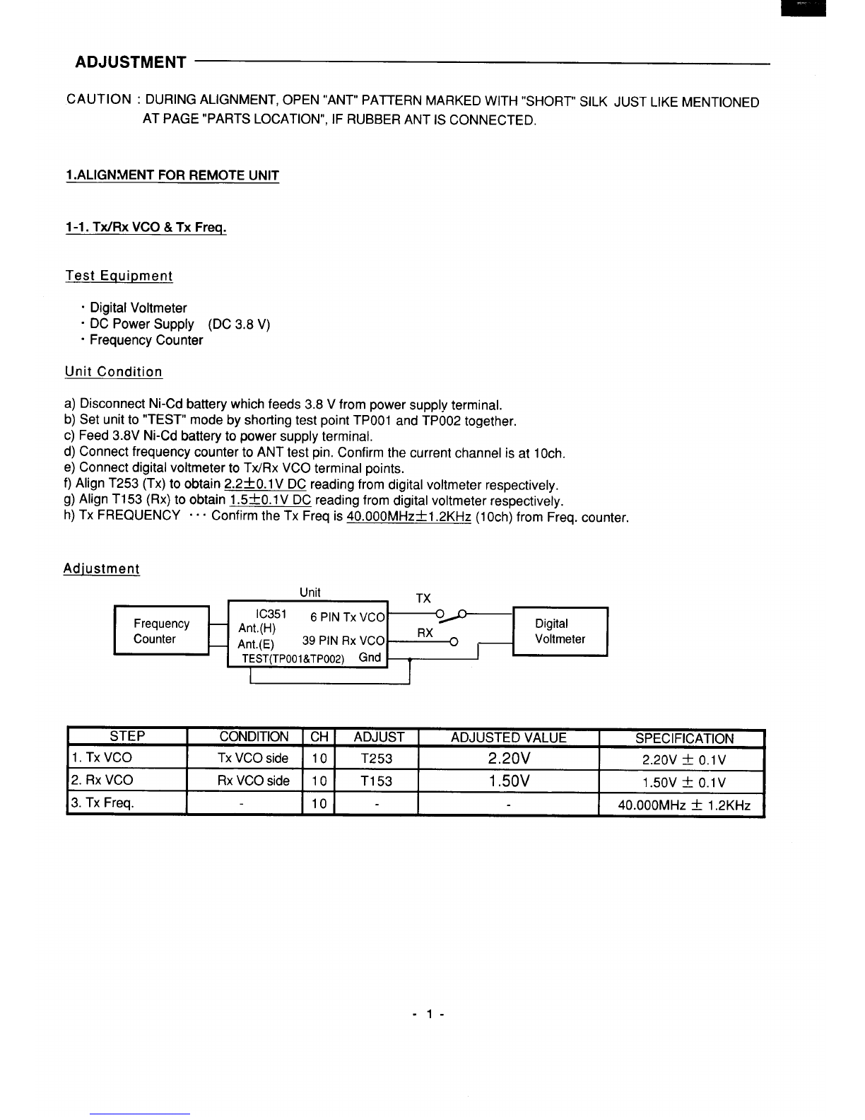
Test Equipment
(see FIG-4,TABLE-4)
.Distortion Meter
.Dummy Load (600 Q)
“FM SSG (50s2 :OPEN TYPE)
.AC Voltmeter (ACVM)
.AC Adaptor (DC 9.0 V---- CENTER MINUS)
Unit Condition
a) Disconnect AC Adaptor.
Open “TEST1” pinto enter the “TEST2” mode. (Now only “TEST2” point is shorting.)
Discharge C401 (JI04), and connect AC Adaptor.
b) Disconnect AF oscillator from TEL line, and connect AC voltmeter in parallel with distortion meter, terminated with
600Q during load to the TEL line.
c) Disconnect Linear detector from CN101 and connect FM SSG (1kHz, 2.0kHz dev., 39.900MHz, 46dB pV) to CNI 01.
Push “PAGE” key 1time in order to enter the Rx mode.
d) Rx IF . . .
e) Rx RF ...
...
f) Rx AF Level “””
. . .
g)CD Level Check . . .
...
...
...
Align T301 to obtain maximum deflection and minimum distortion from the read of AC
voltmeter and distortion meter respectively.
Change output level of FM SSG from 46dB pV~+5dB pV.
Align T1 01, to obtain minimum distortion at the distortion meter (less than 10%).
Change output level of FM SSG from 5dB A V ~46dB AV.
Align VR301 to obtain -5dBm~0.5dBm from read of AC voltmeter, and confirm at the
FM SSG input of
300Hz (46dB pV) :the output of ACVM -6.0dBmt3dBm
3kHz (46dB pV) :the output of ACVM -14.5dBm~3dBm
Switch position S407 ~TONE (TX “OFF”).
Connect OSCILLOSCOPE to CD OUT.
Confirm CD level is High ~Low when FM SSG is O~ + 20dBA.
Confirm CD level is High when FM SSG is O~+4dBp.
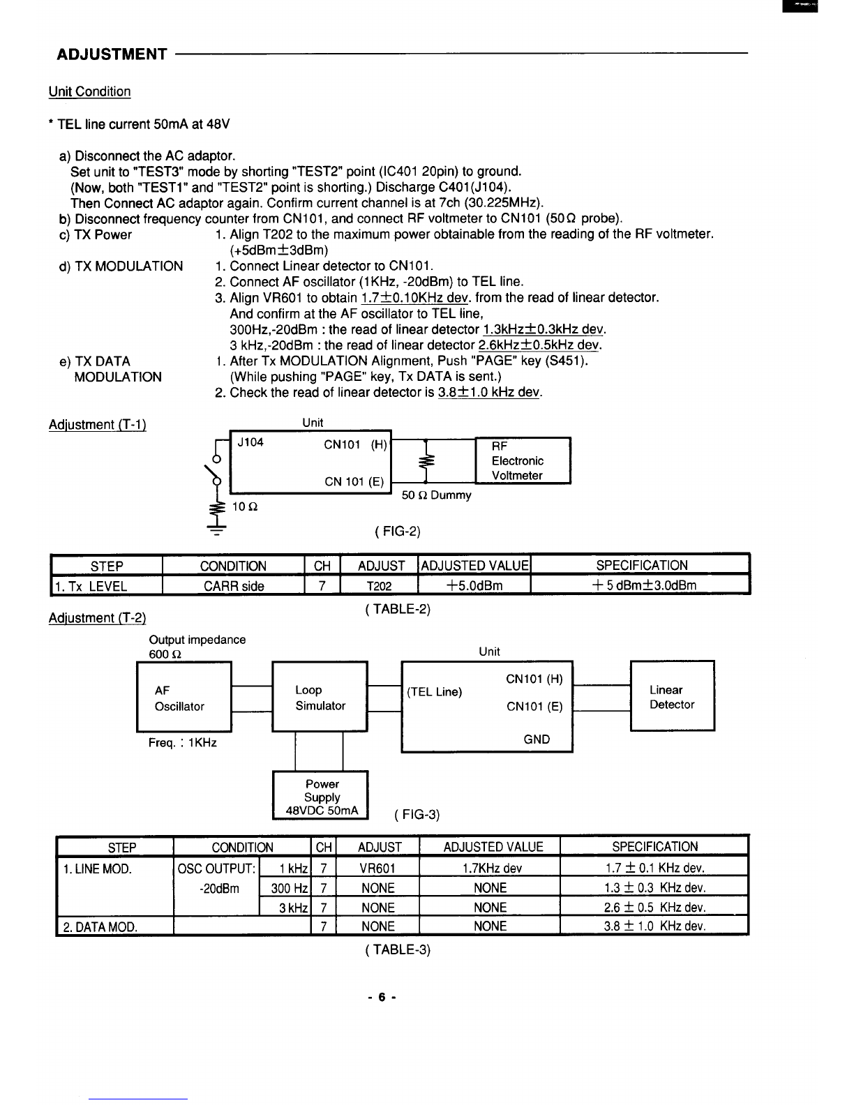
Adjustment
Unit
(FIG-4)
SSG
(TEL .600 C?
CNIOI (H) Loop
FM SSG line) Simulator Voltmeter
CN101 (E)
Mod. :1 kHz
Dev. :2.0 kHz Power Distortion
supply
48VDc,50mA Meter
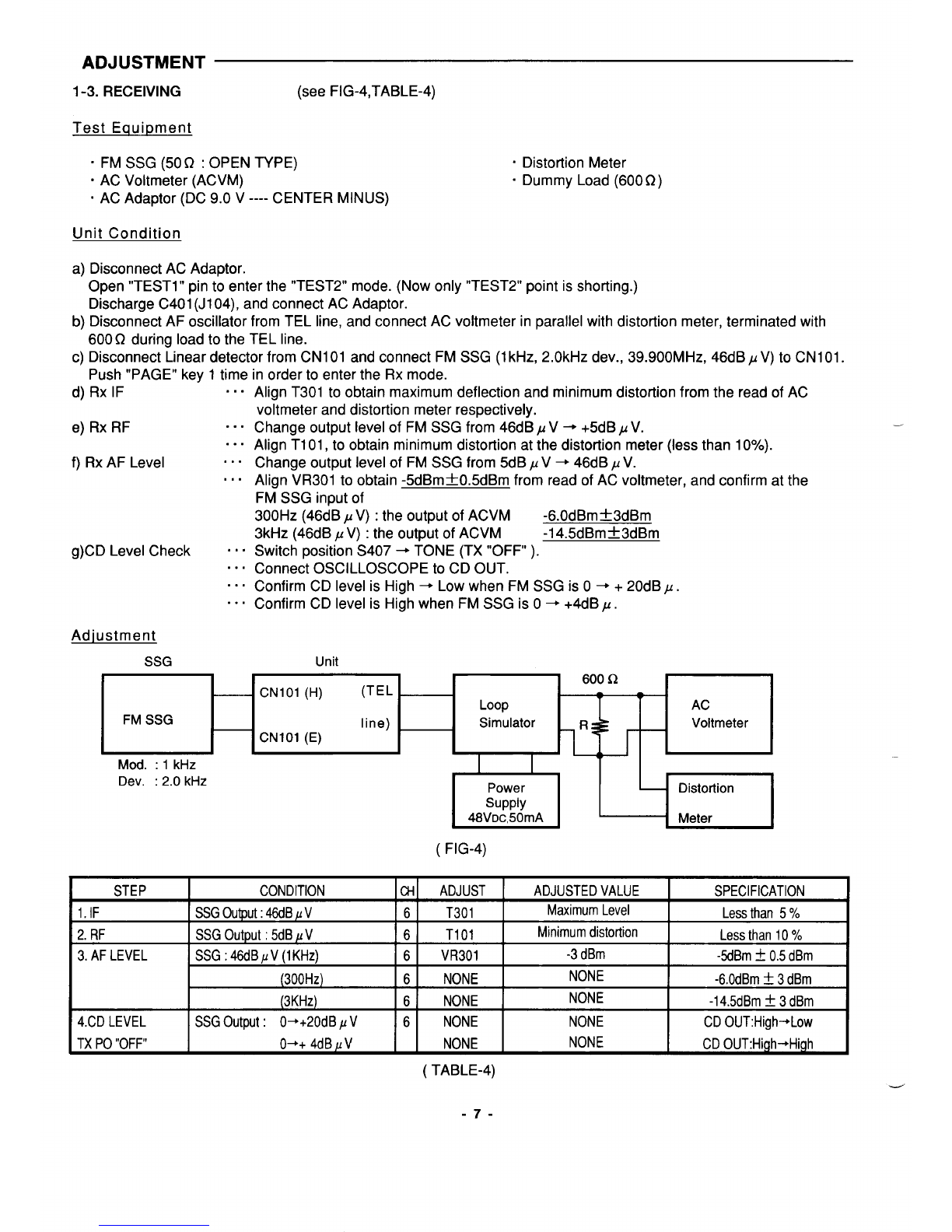
STEP CONDITION a-l ADJUST ADJUSTEDVALUE SPECIFICATION
1.IF SSGOutput:46dB/V 6T301 MaximumLevel Lessthan 5%
2.RF SSGOutput: 5dBKV 6T101 Minimumdistortion Lessthan 10Y.
3. AF LEVEL SSG :46dBPV (1KHz) 6VR301 -3dBm -5dBmt0.5dBm
(300Hz) 6NONE NONE -6.OdBmt3dBm
(3KHZ) 6NONE NONE -14.5dBmt3dBm
4.CDLEVEL SSGOutput: O-+20dB pV6NONE NONE CDOUT:High-+Low
TXPO“OFF” O++ 4dBpV NONE NONE CD OUT:High~High
(TABLE-4)
-7-
-----