- 1 -
1.Cautionary instructions in handling the assy
(Safety instructions)
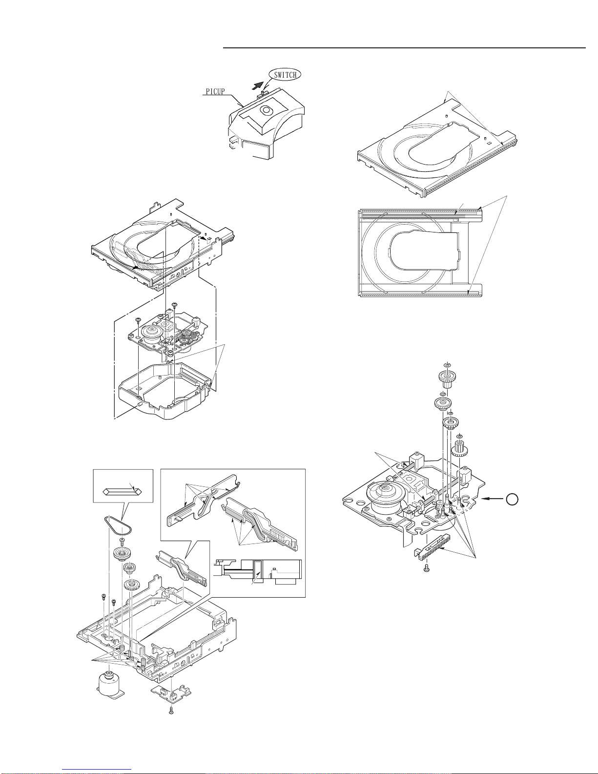
Optical pickup
The laser beam used in the pickup is classified as "class 2". Exposing
your eyes or skin to the beam is harmful. Take care not to do so.
(Caution against static electricity and leakage voltage)
Ground securely the work tables, tools, fixtures, soldering irons
(including those made of ceramic) and measuring instruments used
in the production lines and inspection departments that handle
loaders. The workers shall also be grounded.
(Cautionary instructions in handling)
Do not touch the object lens when handling a loader, or the lens will
be stained, resulting in inadequate playability.
There is no power supply protection circuit provided for this product
or adjustment/inspection device. Short-circuiting may lead to fire or
damage.
Take care so as to protect from exposure to water, the entry of
metallic pieces or dew condensation.
In particular, a strong magnet adjacent to the pickup will not only
get inoperative but can damage the pickup if a small metallic piece,
such as a screw or swarm, enters.
The loader edge can cause injury if inadvertently handled.
Do not touch a rotating disk, or injury may result.
This product is a precision device. Handle carefully.
A shock or dropping will cause misalignment or destruction. If it
should occur, refer to clause 2.
This product is so designed as to endure an initial shock equivalent
to a drop from a height of approx. 90 cm under the packed condition.
After the initial shock, the resistivity will still remain at a level of 50
to 60 G, but the mechanical robustness will weaken.
Do not place in a dusty location.
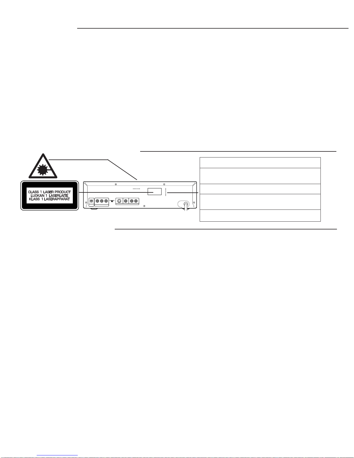
LASER BEAM SAFETY PRECAUTION
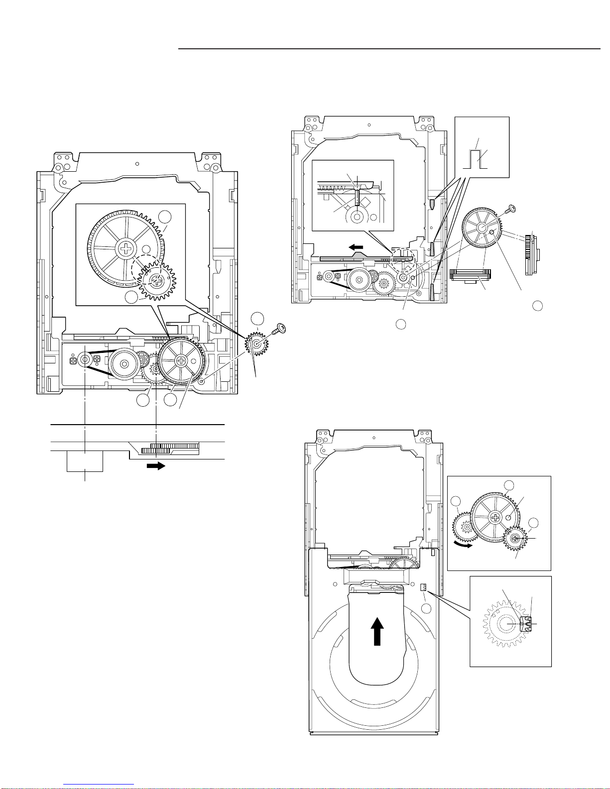
MECHANISM REPLACEMENT The entry and deposition of dirt into or on the pickup lens or moving
section will cause malfunction or degradation.
(Connectors)
Do not connect or disconnect while power is on.
Connecting or disconnecting signal wires or the main power cord
when the power is on may destruct the unit or fixture.
When connecting, push all the way in securely.
An insufficient insertion may cause a bad contact, leading to an
erroneous operation.
Do not connect or disconnect roughly by an excessively strong force,
or a broken wire or bad contact may result.
Semiconductors are connected. Do not touch connector terminals
directly.
If the worker is grounded, there is nothing to worry about static
electricity, but the rust on the connector terminal surface caused by
the touch may result in bad contact.
(Power source)
The power source need be good in quality (free from instantaneous
interruptions or noises).
A low quality power source may well cause malfunction.
(Storage)
Do not place or store in a dusty place or a place where dew
condensation is possible.
The entry and deposition of dirt or dust into or on the pickup lens or
moving section will cause malfunction or degradation.
Also, dew condensation causes rust;the rust penetrate into the
precision part of a pickup, causing malfunction, or degrading the
optical quality of the internal lens and reflector, which also leads to
malfunction.
SPECIFICATIONS
Type ........................................ DVD player
Signal format ........................... NTSC or PAL color
Laser ....................................... Semiconductor laser,
wavelength 650nm
1 mW(DVD) , 0.5mW(CD)
Frequency range..................... 4 Hz to 44 kHz(DVD fs : 96kHz)
(digital audio)
Signal to noise ratio ................ More than 105 dB
Harmonic distortion ................. 0.003 %
(digital audio)
Wow and flutter ....................... Below measurable level
DIGITAL OUTPUT
COMPONENT VIDEO OUT
Y.............................................1.0V
C , C .....................................0.7V
S-VIDEO OUT
Y.............................................1.0V
C.............................................0.286V
VIDEO OUT .................................1.0V
AUDIO OUT .................................1.2V rms
Power requirements.....................AC 110 - 240V , 50/60Hz
Power consumption .....................16 Watts
Dimensions (W x H x D)...............Approx. 360 x 87 x 282 mm
Weight ..........................................Approx. 2.8kg
Specifications subject to change without notice.
p-p (75 ohm)
p-p (75 ohm)
p-p (75 ohm)
p-p (75 ohm)
p-p (75 ohm)
B R
S-VIDEO OUT
DIGITAL
OUT
RL
OPT. VIDEO OUT AUDIO OUT
COMPONENT VIDEO OUT
YC
B
C
R
TV SYSTEM
PAL NTSC
CAUTION – INVISIBLE LASER RADIATION WHEN OPEN AND
INTERLOCKS DEFEATED. AVOID EXPOSURE TO BEAM.
ADVARSEL – USYNLIG LASER STRÅLING VED ÅBNING, NÅR
SIKKERHEDSAFBRYDERE ER UDE AF FUNKTION, UNDGÅ UDS ÆTTELSE
FOR STRÅLING.
VARNING – OSYNLIG LASER STRÅLNING NÄR DENNA DEL ÄR ÖPPNAD
OCH SPÄRR ÄR URKOPPLAD. STRÅLEN ÄR FARLIG.
VORSICHT – UNSICHTBARE LASERSTRAHLUNG TRITT AUS, WENN
DECKEL GEÖFFNET UND WENN SICHERHEITSVERRIEGELUNG
ÜBERBRÜCKT IST. NICHT, DEM STRAHL AUSSETZEN.
VARO – AVATTAESSA JA SUOJALUKITUS OHITETTAESSA OLET ALTTIINA
NÄKYMÄTTÖMÄLLE LASERSÄTEILYLLE. ÄLÄ KATSO SÄTEESEEN.
(AU)