INDEX Page
1. INSTALLATION
(1) Unpacking. .......................................................................1
(2) Telephonelineand ACconnections. .....................................................1
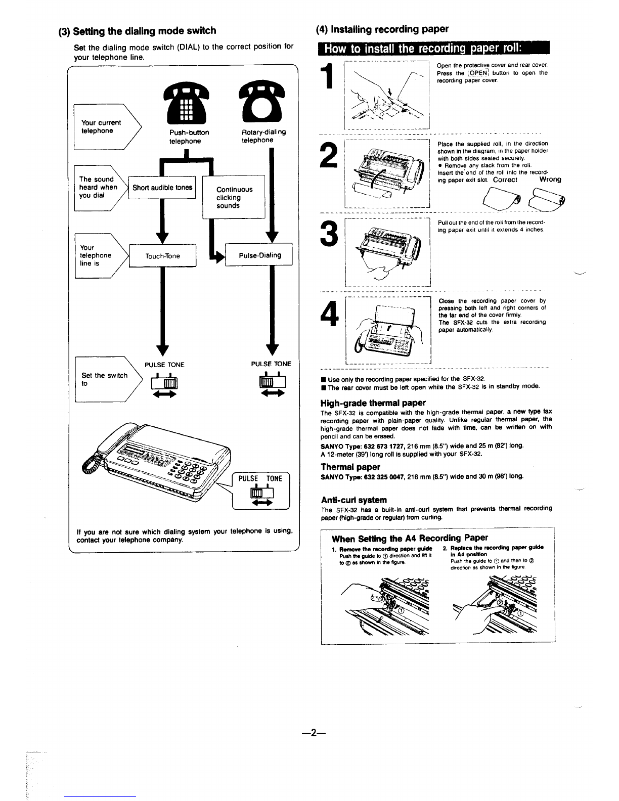
(3) Settingthedialing modeswitch .........................................................2
(4) installing recording paper .............................................................2
(5) Machine initial .....................................................................3
(6) Machine programming .............................................................3-7
2. PERIODICALINSPECTION AND MAINTENANCE ..............................................8
3.OUTLINE
(l) Partnamesandfunctions .............................................................9
(2) Operation panel ...................................................................10
(3) Original documentsprecautions. ......................................................11
4. MECHANICALOUTLINE ...............................................................12
5.TROUBLESHOOTING
5-1. Function description ofeach PCB ..................................................13-15
5-2. Trouble shooting for Mechanical Parts ..................................................15
5-3. Trouble shooting forcircuitry. .....................................................16–20
5-4. Error code list .................................................................20,21
6.REPAIRS
6-l. Removal ofthemainpatts ........................................................22}23
6-2. Replacementofthe main parts .....................................................23,24
6-3. Test Mode .................................................................. 25-30
6-4. RAM CODE LISTand ltsExplanation ...............................................31-34
7.PRINTINGOFTHE REPORTSANDUSTS
7-1. Activity Report ...................................................................35
7-2. One-touch Dial List ...............................................................35
7-3. Speed Dial List ...................................................................36
7-4. FeatureSwitch List ................................................................36
7-5. RAM CODE List ..................................................................37
7-6. Transmission Report ...............................................................38
7-7. TimerTransmission Report ..........................................................38
8.FLOWCHARTOF AUTO RECEPTION MODE
(l) Autoreceptionwith FAX/TELswitchover function isON ......................................39
(2)Auto reception with FAX/TELswitchover function isOFF ......................................40
(3) Answerreception mode .............................................................41 -
9.BLOCKDIAGRAM ANDTHESIGNALFLOW
9-1. Block Diagram .................................................................. 42
9-2. Signal flow ...................................................................43,44
10. SCHEMATIC DIAGRAM
(l) All Connection Diagram ...........................................................45,46
(2) Each Circuit Diagram ............................................................47-61
(3) PWB Wiring Diagram ............................................................62-64
(4)Abbreviatedsignal explanation ........................................................65
ll. PARTSSPECIFICATION
(l) lCconfiguration ................................................................66-71
(2) Parts specification for power supply .....................................................72
(3) Figure of main parts for power supply ....................................................72
12.TfMECHARTS OF EACH COMMUNICATION MODE ..........................................73
13.SIGNALFLOW CHART ...............................................................74
14.EXPLODEDVIEW ................................................................75-n
15.PARTSUST ....................................................................78-83 ~