- 2 -
1. Cautionary instructions in handling the assy
(Safety instructions)
Optical pickup
The laser beam used in the pickup is classified as "class 2".
Exposing your eyes or skin to the beam is harmful. Take care
not to do so.
(Caution against static electricity and leakage voltage)
Ground securely the work tables, tools, fixtures, soldering irons
(including those made of ceramic) and measuring instruments
used in the production lines and inspection departments that
handle loaders. The workers shall also be grounded.
(Cautionary instructions in handling)
Do not touch the object lens when handling a loader, or the lens
will be stained, resulting in inadequate playability.
There is no power supply protection circuit provided for this
product or adjustment/inspection device. Short-circuiting may
lead to fire or damage.
Take care so as to protect from exposure to water, the entry of
metallic pieces or dew condensation.
In particular, a strong magnet adjacent to the pickup will not only
get inoperative but can damage the pickup if a small metallic
piece, such as a screw or swarm, enters.
The loader edge can cause injury if inadvertently handled.
Do not touch a rotating disk, or injury may result.
This product is a precision device. Handle carefully.
A shock or dropping will cause misalignment or destruction. If it
should occur, refer to clause 2.
This product is so designed as to endure an initial shock
equivalent to a drop from a height of approx. 90 cm under the
packed condition.
After the initial shock, the resistivity will still remain at a level of
50 to 60 G, but the mechanical robustness will weaken.
Do not place in a dusty location.
The entry and deposition of dirt into or on the pickup lens or
moving section will cause malfunction or degradation.
DVD MECHANISM REPLACEMENT
(Connectors)
Do not connect or disconnect while power is on.
Connecting or disconnecting signal wires or the main power cord
when the power is on may destruct the unit or fixture.
When connecting, push all the way in securely.
An insufficient insertion may cause a bad contact, leading to an
erroneous operation.
Do not connect or disconnect roughly by an excessively strong
force, or a broken wire or bad contact may result.
Semiconductors are connected. Do not touch connector terminals
directly.
If the worker is grounded, there is nothing to worry about static
electricity, but the rust on the connector terminal surface caused
by the touch may result in bad contact.
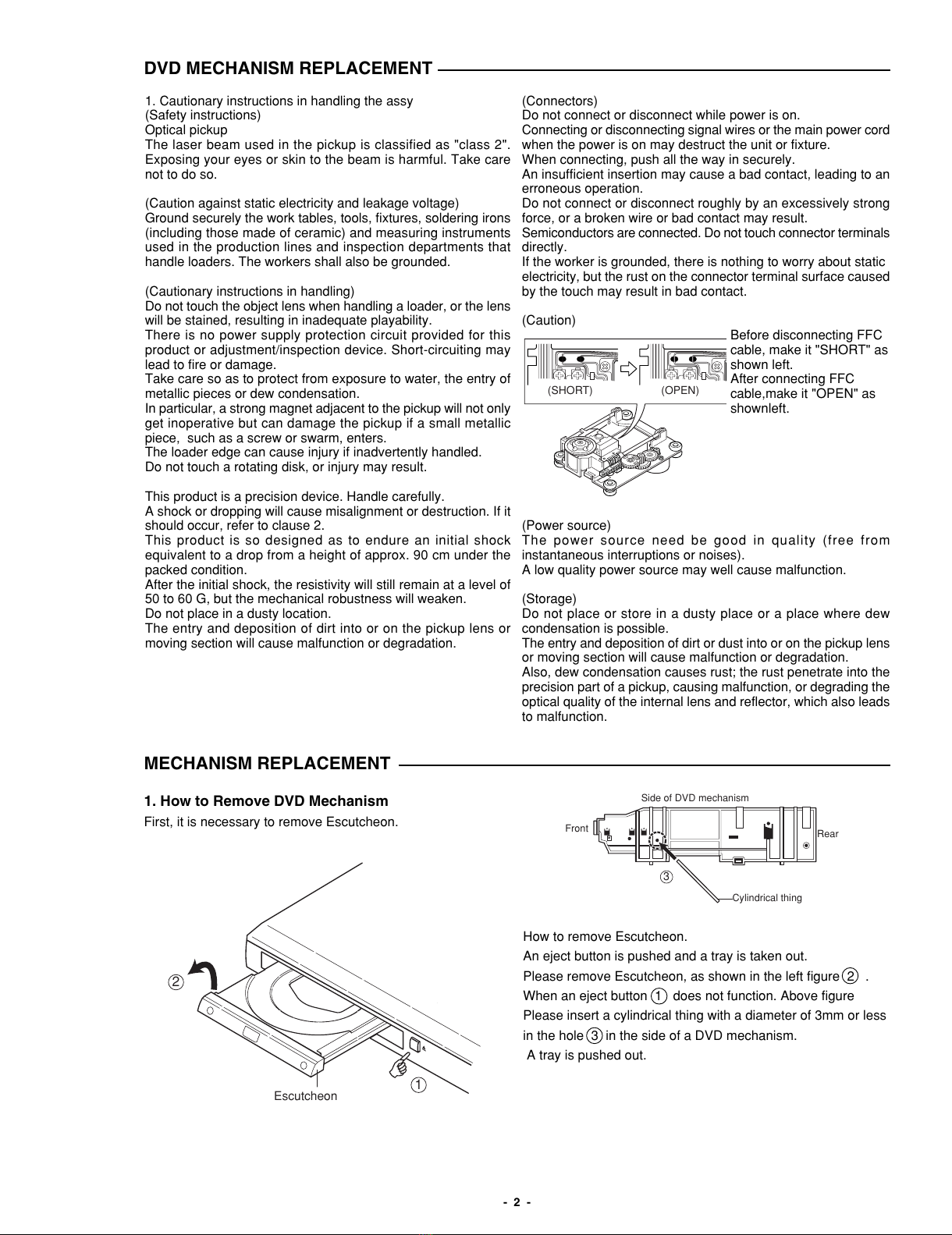
(Caution)
Before disconnecting FFC
cable, make it "SHORT" as
shown left.
After connecting FFC
cable,make it "OPEN" as
shownleft.
(Power source)
The power source need be good in quality (free from
instantaneous interruptions or noises).
A low quality power source may well cause malfunction.
(Storage)
Do not place or store in a dusty place or a place where dew
condensation is possible.
The entry and deposition of dirt or dust into or on the pickup lens
or moving section will cause malfunction or degradation.
Also, dew condensation causes rust; the rust penetrate into the
precision part of a pickup, causing malfunction, or degrading the
optical quality of the internal lens and reflector, which also leads
to malfunction.
(OPEN)(SHORT)
1. How to Remove DVD Mechanism
First, it is necessary to remove Escutcheon.
How to remove Escutcheon.
An eject button is pushed and a tray is taken out.
Please remove Escutcheon, as shown in the left figure 2 .
When an eject button 1 does not function. Above figure
Please insert a cylindrical thing with a diameter of 3mm or less
in the hole 3 in the side of a DVD mechanism.
A tray is pushed out.
3
Side of DVD mechanism
Front Rear
Cylindrical thing
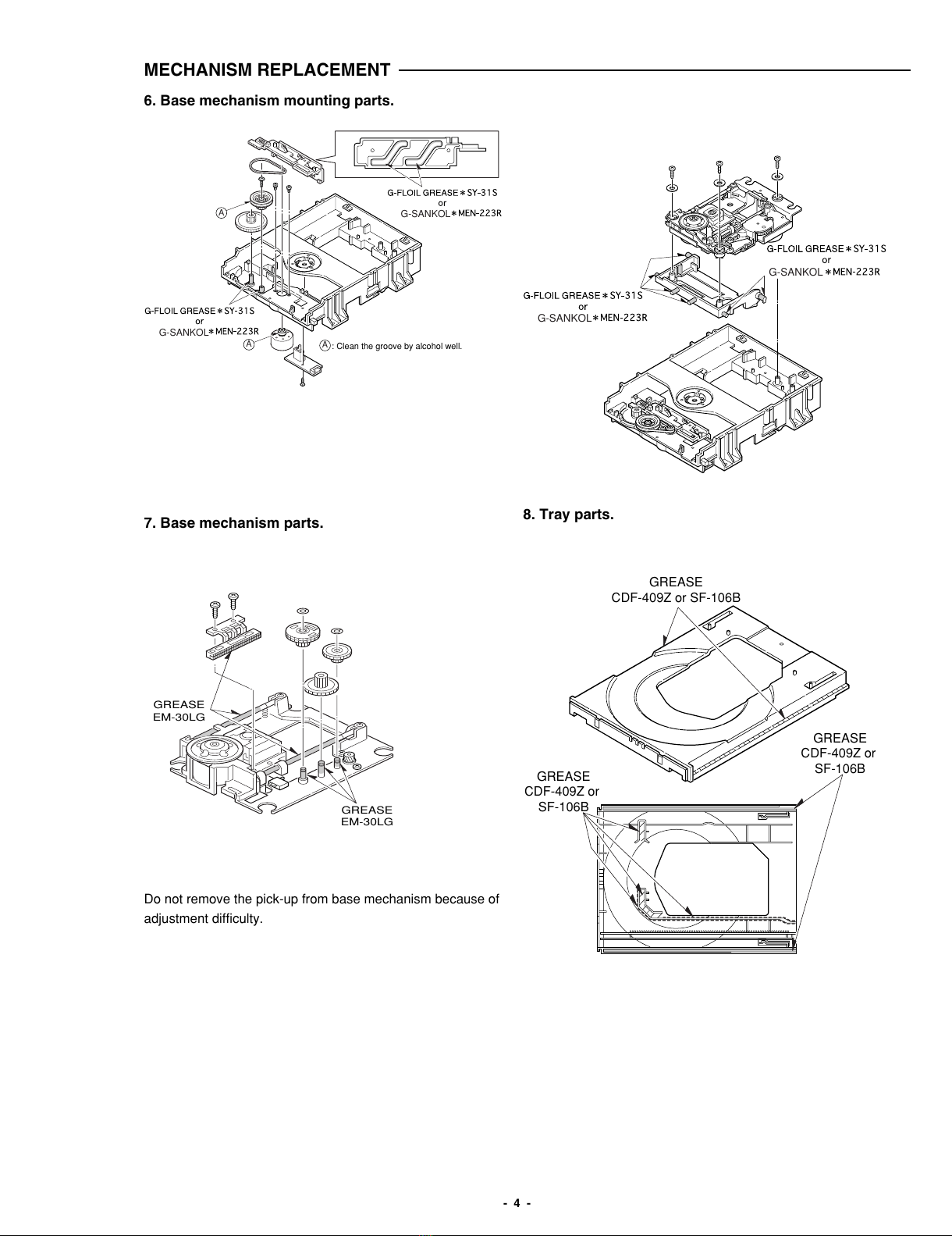
MECHANISM REPLACEMENT
1
1
1
2
Escutcheon