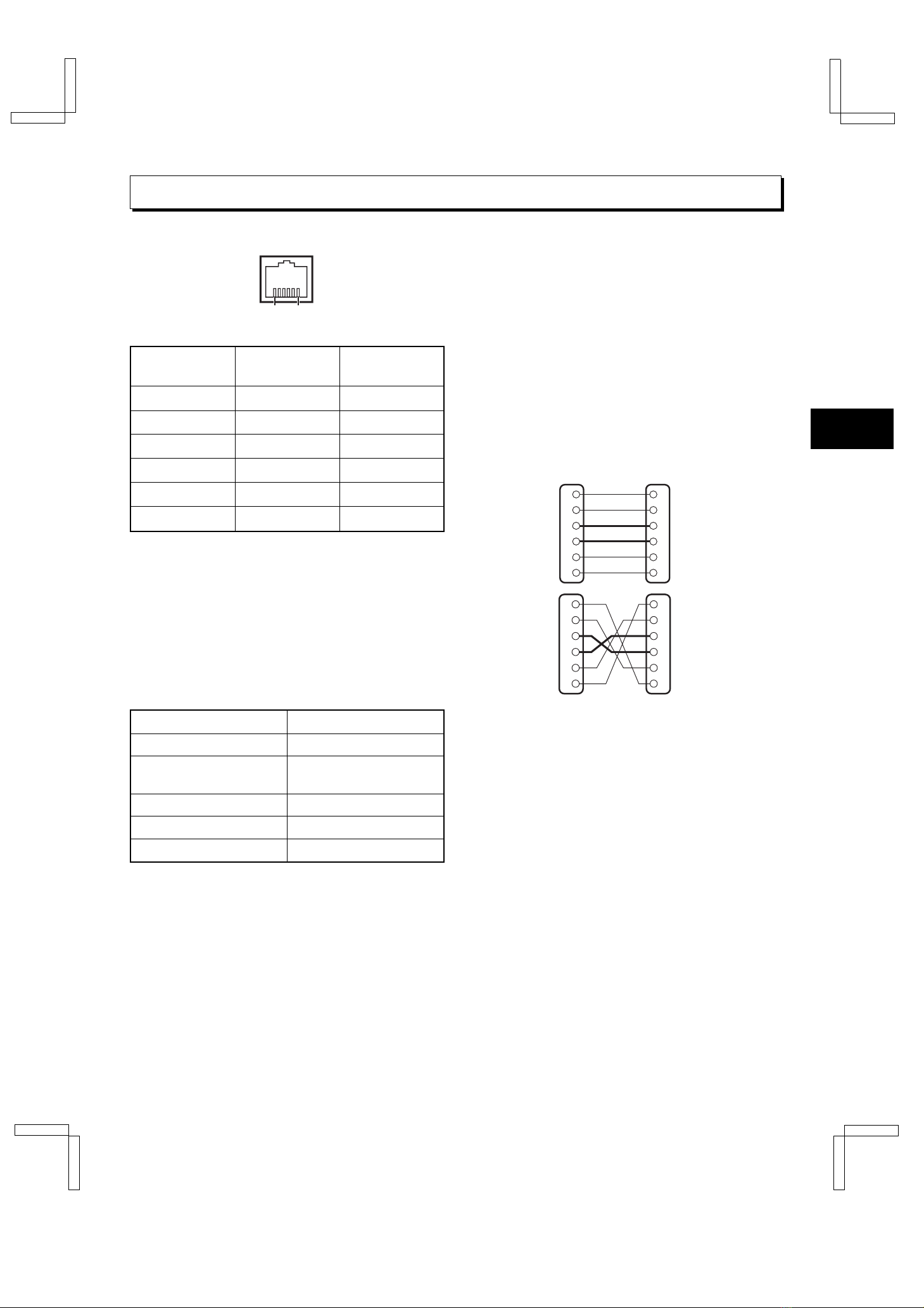
SETTING FOR RS-485 or RS-232C USE
The RS-485 interface can be used to operate the VCR
using a SANYO brand system controller. Furthermore,
the RS-232C interface can be used to operate the VCR
using a computer.
NOTES:
œThis can only be used when the RS-485/232C
interface board (VZU-485/232C) is installed.
œRefer to the instruction manuals for the system
controller and/or the computer.
Setting the Address and Data Transfer
Speed
œMake this setting without a cassette tape inserted.
1Press the COUNTER RESET button for 3 seconds
or more.
ø“485” or “232” appears on the digital display.
2Turn the JOG dial to select the interface being
used, RS-232C or RS-485.
ø“232” or “485” appears on the digital display.
œWhen setting “232”, carry out step 3and then
step 6.
3Turn the SHUTTLE ring clockwise.
4Turn the JOG dial to set the VCR address (from
000 to 127).
øThe address set appears on the digital display.
5Turn the SHUTTLE ring clockwise.
6Turn the JOG dial to set the data transfer speed
(19200, 2400, 4800, 9600).
øThe data transfer speed set appears on the
digital display.
7When finished, Press the COUNTER RESET
button.
NOTE:
œWhen the MENU RESET button is pressed, the
setting appearing on the digital display is reset to the
default setting.
Settings when using RS-485
1Press the MENU button to display the MAIN MENU.
2Turn the JOG dial to select the “9.OTHERS”line,
then turn the SHUTTLE ring clockwise.
øThe (OTHERS) menu appears.
<OTHERS>
*ALARM@LOG
*POWER@FAILURE/DEW
*TERMINAL@SET@@@@SET1
*RS-485@SET
@@STATUS@INFO.@@@Y
@@ALARM@INFO.@@@@Y
3Turn the JOG dial until the “STATUS INFO.”setting
is highlighted, then turn the SHUTTLE ring
clockwise.
4Turn the JOG dial to set the “STATUS INFO.”
setting, then turn the SHUTTLE ring clockwise.
Y. . . . . . . . . . The VCR status information is
output at the RS-485 connector.
N. . . . . . . . . . The status information is not
output at the RS-485 connector.
5Turn the JOG dial until the “ALARM INFO.”setting
is highlighted, then turn the SHUTTLE ring
clockwise.
6Turn the JOG dial to set the “ALARM INFO.”
setting, then turn the SHUTTLE ring clockwise.
Y. . . . . . . . . . The VCR alarm information
(alarm recording start and stop)
and video loss information are
output at the RS-485 connector.
N. . . . . . . . . . The VCR alarm information
(alarm recording start and stop)
and video loss information are
not output at the RS-485
connector.
7Press the MENU EXIT button.
8Set the TERMINATE switch on the back panel to
the “ON”or “OFF”position
OFF side . . . Not terminated
ON side . . . . Terminated
NOTE:
œWhen a warning state (non-recording, mechanical
problem or clog detection) occurs, the warning state
is output from the RS-485 connector. However,
non-recording warning states are not output if “NON
REC”is set to “N”in the (WARNING
OUT/CONTROL SET) menu. In addition, the clog
detection warning state is not output if “CLOG
DETECT.”is set to “N”in the (GENERAL SET) menu.
RS232C (RF4QR/NA GB Operation Board)
Fri. Sept., 06/2002
English 5