Sanyo G-2915NK User manual

SANYO
PORTABLE
STEREO
MUSIC
SYSTEM
G-2915NK
SERVICE
MANUAL
A
PRODUCT
OF
SANYO
ELECTRIC
CO.,
LTD.

GENERAL
Audio
Input
Level:
Microphone
2mV,
400K
ohm
Transistors:
17
(for
tape
recording)
impedance
wey
|
:
3
SPEAKER
SECTION
ee
ae
120/200/220/240V
asshole
inking
Sine
:
HOOV
(Six
“OM
standard
batteries)
Dimensions:
7-7/8"
x
3-1/8"
x
10-1/8
Dimensions:
2N-1/4
IW)
y
6-1/4"
(D)
x»
16-3/4'"(H)
PHONO-PLAYER
SECTION
Weight:
Approx.
23
ibs.
(10.5
kg)
Turntable
Speeds:
33-1/3,
45
&
78
rpm
TUNER
Pickup
System:
Ceramic
Stereo
Cartridge
{part
#R-SO7135)
with
Sapphire
Stylus
Frequency
Ranges:
MW
530
—
1605kHz
(part
#R-SO7146)
Oe
eo
Turntable
Size:
7”
dia.
EM
Be
te
Wow
&
Flutter:
0.3%
intermediate
Frequencies:
MW/SW
455kHz
FM
10.7MHz
CASSETTE
SECTION
Effective
Sensitivities:
MW
400uV/m
Recording/Erasing
System:
AC
Bias
SW
400unV/m
:
Tape
Speed:
1-7/8"
FM
12uV
|
Rewind/F.Forward
Time:
120
sec.
(C-60
Cassette)
FM
Stereo
Separation:
20dB
.
Wow
&
Fiutter:
0.35%
AUDIO
AMP
SECTION
8
TRACK
SECTION
Output
Power:
3.5W/channel
.
Recording/Erasing
System:
AC
Bias
Frequency
Response:
30.
—
20000Hz
Tape
Speed:
3-3/4
ips
Output
Terminals:
Speaker:
8
ohms
Wow
&
Flutter:
0.35%
AM
ALIGNMENTS
AM
JF
and
RF
Alignment
1
MW
SIGNAL
FREQUENCY
AND
DIAL
SETTING
COMPONENTS
TO
BE
INPUT
MODULATION
OF
SSG
OF
RADIO
ADJUSTED
FOR
MAX.
OUTPUT
Thru
Loop
455KHz
30%
~
Lower
end
{FT.
T-7,
T-8,
T-9
Antenna
3.2MHz
30%
Lower
end
OSC
coil
L-8
12MHz
30%
Upper
end
OSC
trimmer
CT-6
3.5MHz
,
30%
3.5MHz
Ant.
coi}
L-6
11.5MHz
30%
11.5MHz
530KHz
1605KHz
30%
Upper
end
600
KHz 30%
600
KHz
1400
KHz
30%
1400
KHz
Ant.
trimmer
CT-4
OSC
coil
L-9
30%
Lower
end
OSC
trimmer
CT-7
Ant.
coil
L-5
Ant.
trimmer
CT-5
SVR-1:
Tp1
~Tp2
V=0.6V
Repeat
step
4
and
5,
Repeat
step
8
and
9.
FM
IF
Alignment
-
Connect
sweep
generator
to
CT-3
Tune
for
max.
gain
and
symmetry
and
oscilloscope
to
test
point
Tp-3
of
response
curve
(Fig.
1)
Connect
sweep
generator
to
CT-3
Tune
for
symmetricai
‘'S’’
curve
2
10.7MH
;
.
Bann
and
oscilloscope
to
test
point
Tp-4
(Fig.
2)
Fig.
1
n
6
NO
Symmetrical
response
curve
10.7MHz
marker
Symmetrical
"S"’
curve
10.7MHz
marker
ee
mE
weed
Qe
oe
Babe
ess
Sam
Are
ae
tn
te

\
A
tA
ee
re
ce
ee
Af
Rl
NN
TR
eA
Ren
A
Al
A
ER
A
LF
pe
ne
a
NN
EE
ee
ne
tment
ee
ee
RF
Alignment
STEP
SIGNAL
FREQUENCY
AND
DIAL
SETTING
COMPONENTS
TO
SE
INPUT
MODULATION
OF
SSG
OF
RADIO
ADJUSTED
FOR
MAX.
OUTPUT
Thru
dummy
S8MeHz
Lower
end
OSC
coi}
L4
Ant.
Fig.
3
108MHz
Upper
end
OSC
trimmer
CT-3
90
MHz
9O0MHz
RF
coil
L-2
90MHz
S9O0MHz
Ant.
coil
L-1
106MHz 106MHz
RF
trimmer
CT-2
106MHz
1O06MHz
ANT
trimmer
CT-1
Repeat
STEP
3,
4,
5and
6.
Fl
Bates
Z
3
i
S.S.G.
35
ohm
!
37.5
ohm
()
To
Aerial
terminai
{Antenna)
OQ
To
EarthiGround)
Se
ite
ee
eek
S
3
75
ohms
FM
MPX
Adjustment
STEREO
SIGNAL
STANDARD
GENERATOR
COMPONENTS
STEP
SUBJECT
SIGNAL
MAIN.
LEFT
TO
BE
INDICATION
|
GENERATOR
PILOT
RIGHT
AND
ADJUSTED
SIGNAL
SUB
SIGNAL
;
|
Adjustment
L-102
1
of
19K
Hz
|
-103
TP-102
Max.
Output
and
38KHz
:
Adjustment
2
ot
main
channel
Separations
98MHz
60dB
10%
MOD.
e e
3
Sub
channel
L-103
speaker
Min.
distortion
Output
left
channel
output
;
|
30%
MOD.
with
|
right
channel
SV
R-101
.
Min,
Output
(or
right
chan-_
ne!
output
{or
left
channel)
Right
channel
|
o
|
VV.
OSCILLOSCOPE
Left
channei
FM
STANDARD
SIGNAL
GENERATOR
oes

PARTS
LIST
PACKAGE
PARTS
R-4770922
|
Instruction
book
R-4072075
individual
carton
R-4170320
R-477070
Tag,
Power
R-357237
Polyethylene
bag
Poiyethytene
bag,
160
x
245
x
0.05,
AC
cord
Poiyethylene
bag,
100
x
240
x
0.05,
Mic
Polyethylene
bag,
240
x
320
x
0.05
Protector,
19
x
19
x
100,
Battery
case
&
Control
left
Protector
5
x
21
x
150,
8
track
&
Cassette
Styro-foam
cushion,
Unit
right
&
left
ACCESSORIES
| |
R-S07137
R-SO7138
R-$07037
R-S8574b
R-S8575b
R-S3777
Microphone,
Dynamic
with
remote
on-off
switch,
400
ohms
Microphone,
Dynamic,
400
ohms
Cassette
Tape
Plug
Adaptor,
Siemens,
Pitch
19mm
Plug
Adaptor,
England,
Pitch
16.7mm
AC
Cord
CABINET
&
APPEARANCE
PARTS
1
R-A70683
Case
complete
assembly
R-A
70684
Case
assembly
R-317227
Case
2
R-2670699
Frame
3
R-127767
Fix
metal
front
4
R-127829
Fix
metal
rear
5
R-127760
Fix
metal
right
&
left
6
R-127759
Fix
metal
7
Tap.
Screw,
Pan
Hd.
(2)
3x8
8
R-S87096
Hinge
assembly
9
R-118045
Fix
metal,
Hinge
10
R-4070778
Spacer
11
Screw
Oval
Hd.
3
x
12
12
R-S$870384
Lock
assembly
13
Tap.
Screw
Pan
Hd.3
x8
14
R-397085
Handie
R-397166
Handle
base
R-117192
Fix
metal,
Handle
base
15
Screw
Pan
Hd.
4
x
12
16
R-3970549
Base
17
Screw
Bind
Hd.
3
x
10
18
Nut
Hex
Hd.
with
Washer
19
R-437193
|
Felt
10
x
30
x
5t
20
Neoplane
30
x
40
x
&t
21
R-12080
Special
nut
36
22
R-A70685
Panel
assernbly
30
R-357146
Antenna
holder
R-2670716
Decoration
metal,
Cassette
lid
31
R-2670708
Decoration
metal,
Cassette
azimuth
32
R-A70686
8
Track
lid
assembly
R-327286
|
8
Track
lid
R-2670706
|
Door
8
Track
cartridge
R-157346
|
Shaft,
Door
R-127761
|
Clip,
Door
R-157342
Spring,
Door
R-387418
3
Sign
board,
Channel
R-2670707
|
Decoration
metal,
Channel!
33
R-A70637
|
Battery
case
assembly
R-3970550
|
Battery
case
34
|
R-327292
|
Fix
plastic
board
R-157343
|
Coil
spring,
+
&
—
terminal
R-157344
Cail
spring,
—
terminal
R-237119
Terminai
+
R-237120
Terminal
—
Lug
3x6
35
R-23970551
Knob
36
R-127762
Spring
metal
| |
Tap.
Screw,
Pan
Hd.,
2.6
x
6
R-357247
Ribbon
37
R-3970552
Rest
stand,
Pick-up
Tap.
Screw,
Pan
Hd.
with
Washer
"F’’,
3x8
38
R-A70688
Knob
assembly,
Tuning
Key
ee
:
Part
No.
|
Description
a
ee
a
ee
|
we
eNO
BNNNNN
AH
ROWDRRANWH
OB
ea
~—
ak
ed A}
a
ed
ed
wt
a
ee
ee
eee
ee
(1)
(1)
40
41
42
43
44
45
46
CABINET
&
APPEARANCE
PARTS
|
R.A708R9
R-3970555
R-3970556-L
R-327208
R-397076
R-3970556-M
R-325153
R-447839
R-2670709
K
nob
assembly,
Rec./Vol./Rass/T
reble/
Balance/Band/Function
Knob,
Pop-up/Program
Knob,
Rec.
Knob,
Speed
select
Knob,
Mic
mixing
Knob,
Fast
Forward,
8
Track
Adaptor,
45
rpm
Disc
Turn-table
rubber
mat
Metai
disk,
Turn-table
Tap.
Screw,
Oval
Hd.,
3
x
30,
Pane!
ass’y
‘Tap.
Screw,
Oval
Hd.,
3
x
40,
Panel
ass‘y
Tap.
Screw,
Pan
Hd.,
3
x
8,
8
Track
lid
SPEAKER
BOX
ASSEMBLY
(RIGHT)
R-A70680
R-A70691
R-317230
R-2670671
R-$870382
R-117205
R-S870385
R-3970549
R-237114
R-$07136
R-12011
R-437025
R-$87143
Speaker
box
complete
Case
assembly
|
Case
Frame
Buffle
plate
assembly
Hinge
Fix
metal,
Key
Base
Special
washer,
Buffle
plate
Screw,
8ind
Hd.,
3
x
10,
base
Nut,
Hex
Hd.
with
Washer,
base
Tao.
Screw,
Flat
Hd.,
3
x
10
Tap.
Screw,
Oval
Hd.
3
x
20
Tap.
Screw,
Oval
Hd.,
3
x
10,
Hinge
Tap.
Screw,
Pan
Hd.,3
x8
Speaker,
8
ohm,
1.6W
Lug
Nylon
tube,
4¢
x
27
Cushion,
felt
45
x
45
x
2
Nut,
Hex
Hd.
with
Washer
Cord
assembly,
Speaker
lead
&
piug
SPEAKER
BOX
ASSEMBLY
(LEFT)
63
64
65
66
R-A70692
R-A70693
R-317232
R-2670670
R-S07136
R-72011
R-437035
R-S87143
Speaker
Box
Assembly,
without
speaker
Speaker
Box
only
Box
Frame
Speaker,
8
ohms,
1.6W
Lug
Nyton
Tube,
4¢
x
27
Cushion,
Feit
45
x
45
x
2
Nut,
Hex
Hd.
with
Washer
Cord
Assembly,
Speaker
lead
&
plug
tod
BE
NO
0
ee
J
{
(1)
(1)
wt
Pak
a
ok ot
PANEL
MECHANICAL
PARTS
—4—
R-127770
R-2670712
R-157345
R-S870383
R-4170321
R-117886a
R-127764
R-32315
R-247137
R-157189
R-325017
R-147054
R-2670378
Chassis
Dial
scale
Dial
pointer
Shaft
assembly
Nut,
Hex
Hd.,
M8
Cushion,
Indicator
Pressure
metal,
Indicator
_
Fix
metal,
Mic
mixing
SW
Drum
Special
screw,
VC
—
Drum
Washer
Spring
2.66
Coil
spring,
Drum
Dial
cord
strings,
_-335
Pulley
Pulley
shaft
Heat
sink
Tap.
Screw,
Pan
Hd.,
3
x
6,
Heat
sink
a
eR
eh
Es
ne
i
EAE
ah
ato
I
aU
oo
ee
oe
ee
ee
ee
eee
ee
a
ee
BWW
—
NA
ee
GR
A
A
Me
AA
A
Lo
Aiea
Rea
5
a

EXPLODED
VIEW
(Case)
2)
@
@
(2)
(

ee
ee
9ARTS
LIST
67
638
PANEL
MECHANICAL
PARTS
R-397004
R-157140
R-127763
R-417735a
R-127765°
R-1177390
R-127726
R-415279
R-117739c
R-447843
R-4770977
R-1170533
R-157336
R-1170534
R-1170539
R-1170538
R-11
70531
R-157335
R-157331
R-1170537
R-147047
R-711
70536
R-147047
R-157330
R-1170535
R-147047
R-157239
R-157196
R-157369
R-11
70532
R-147047
R-1170530
R-S870389
R-157334
R-157327
R-S870390
R-247474
R-157328
R-S870391
R-157332
R-157333
ee
a
A
Pipe,
Pick-up
Spring
pin,
Pick-up
Fix
metal,
Mic
jack
Tap.
Screw,
Pan
Hd.,3
x8
Support
Fix
metal,
Cassette
shield
case
Tap.
Screw,
Pan
Hd.,
2.6
x
6,
shield
case
Shield
case,
Cassette
Shield
plate,
Cassette
Circuit
Board
Tap.
Screw,
Pan
Hd.
with
Washer
“F",
2.6
x6
Protector,
Cassette
OSC
Circuit
Board
Shieid
case,
8
Track
OSC
Protector,
35
x
35
x
10,
8
Track
C.B.
Shield
plate,
8
Track
C.B.
Screw,
Pan
Hd.,
2.6
x
4
Shieid
plate
Protector,
46
x
24
x
0.8,
Shield
plate
Holder,
FM
Stereo
lamp
&
8
Track
lamp
Lable,
Connector
Tap.
Screw,
Pan
Hd.,
3
x
8,
Bronze
Fix
metal,
8
Track
lid,
right
Screw,
Pan
Hd.,
3
x
24
Washer,
Flat,
3.3x8x
0.5
Spacer,
Pop-up
Fix
metal,
8
Track
lid,
left
Fix
metal,
8
Track
C.B.,
right
Fix
metai,
3
Track
C.B.,
left
Tap.
Screw,
Pan
Hd.,
3
x
6
Support
bracket,
Right
Tap.
Screw,
Pan
Hd.,
3
x
12
Spacer,
Support
bracket
Coil
spring,
Support
bracket
Pop-up
fever
Special
screw
with
Washer
Pop-up
link
Special
screw
with
Washer
Spring,
Link-lever
Lock
plate
Special
screw
with
Washer
Spring
Washer,
Felt3x10x1
Spring
Nut,
Hex
Hd.,
3
Spring,
Mechanism
—
Support
bracket
Tap.
Screw,
Pan
Hd.,
3
x
10,
Mechanism
Support
bracket,
Left
Special
screw
with
Washer
Fix
metal,
F.F
switch
Lever
assembly,
Recording
Tap.
Screw,
Pan
Hd.,3
x
8
Spacer
Spring
Arm
assembly,
Recording
Spacer
Coil
spring
Tap.
Screw,
Pan
Hd.,2.6
x8
Lever
assembly,
Channet
Spacer
Tap.
Screw,
Pan
Hd.,
26x6
Spring
oe
seen
ee
ives
asap
oQoaias
awe
ae
Se
SS
SS
OSS
eS
Se
ROR
ae
107
100
101
102
103
104
105
106
at
ne
pe
apr
ae
ee
et
0
ame
NO
a
L801
VR254
VR251,253,
255
VR252
$2
31
ne
eg
ce
re
entre
ER
CE
A
R-A70676
R-A70679
R-A70670
R-247284
R-A70677
R-A70671
R-247144
R-A70678
R-A70672
R-A70673
R-S07133
R-S07135
R-SO7146
R-S5743
R-S5716
R-W1756
R-R1167002
R-R1167003
R-R1167004
R-S47151
R-S47152
R-S47026
R-$57019
R-S47057
R-S47061
R-$2720
R-S4734
R-S2766
R-S27117
R-S1721
R-S17134
R-S2115
R-W77060
R-S3010
R-S3741
R-377033-12
R-12004
R-127500
R-12011
R-S87827
R-$87828
R-S47150
Circutt
bDOara
assembry,
TUNER
Circuit
board
assembly,
MPX
Circuit
board
assembly,
AMP
Circuit
board
assembly,
MIC
Circuit
board
assembly,
CASSETTE
Special
screw
Circuit
board
assembiy,
CASSETTE
OSC
Circuit
board
assembly,
8
TRACK
Special
screw
Circuit
board
assembly,
8TRACK
OSC
Circuit
board
assembly,
CONTROL
Circuit
board
assembiy,
POWER
Nut
Hex
Hd.,
3
Tap.
Screw
Pan
Hd.,
3x
8
Washer
Flat
3.3
x
10x
1
Tap.
Screw
Pan
Hd.,3
x6
Pickup
assembly
Cartridge
Stylus
Motor,
DC,
Phono
Turntable
Choke
coil,
Motor
Volume
50K
MN
Volume,
50K
8
Voiume,
50K
A
Rotary
switch,
Function
Rotary
switch,
Band
Push
switch,
Mic
mixing
Indicator
Rotary
switch,
Power
select
Tap.
Screw,
Pan
Hd.,
Rest
switch,
Phono
Tap.
Screw,
Pan
Hd.
with
Washer
“F',
3x8
Jack,
Speaker
Switch,
Power
Jack,
Head
phone
Jack,
Mic.
Terminai,
Power
Tap.
Screw,
Pan
Hd.,
3
x
6
Rod
antenna
Screw,
Bind
Hd.,
3
x
10
Washer,
Flat,
3.3
x
10x
1
Washer,
Sprina,
3
Socket,
Rod
antenna
Power
transformer,
AC
120/
200/220/240V
Tap.
Screw,
Pan
Hd.
with
Washer
“F’,
4x
10
Nut,
Hex
Hd.
with
Washer,
4
2P
lug
3P
lug
Housing
12P,
Cassette
8
track
Lug
Lug,
Large
iug
Nylon
tube
4¢
x
60
Battery
terminai,
+
Battery
terminal,
—
Push
switch,
8
Track
&
F.F
channel
Screw,
Pan
Hd.,
2x
4
Nut,
Hex
Hd.,
2
SEMICONDUCTORS
Diode,
SLP-24,
8
Track
channel!
Diode,
SLP-24,
Stereo
[ndicator
——
ey
Wa
st
a
es
Ot
_—
>
Mm—
=~
p90)
ON
N)
-
NO
Nm
we
ee
ek
wk
CD
et
wet
et
AD
—
A}
oe
a
&
7
4

EXPLODED
VIEW
(8)
%
(
\
x

PARTS
LIST
PANEL
ELECTRICAL
PARTS
TUNER
(RF
AMPLIFIER)
CIRCUIT
BOARD
2a
Maree
ermal
rr
pp,
CAPACITORS
SEMICONDUCTORS
C806
Electrolytic,
10mfd
10V
1
TRI1
Transistor,
2SC668
E
1
C801,802
Ceramic,
S5000F,
+10%,
35V
2
TR2
Transistor,
2SC668
D
1
C803
Ceramic,
0.02mfd,
+100
—0%
1
TR3
Transistor,
2SA222
1
35V
IC,
LA1201C
1
02,3,4
Diode,
18188
FM
3
RESISTORS
D5
Diode,
1S188
AM
1
D1,6,7
Diode,
181588
3
R811,861
Carbon,
220K
ohm,
+5%,
1/4W
2
R812,862
Carbon,
220
ohm,
+5%,
1/4W
2
RESISTORS
R1,11
.
Carbon,
680
ohm,
+10%,
1/4W
2
CASSETTE
PARTS
.
R24
Carbon,
2.2K
ohm,
+10%,
1/4W
2
.
R3
Carbon,
39K
ohm,
+10%,
1/4W
1
R-S97014
Cassette
mechanism
assembly
1
R5
Carbon,
180K
ohm,
+10%,
1/4W
1
R-$5732
Motor,
DC
(1)
R63
Carbon,
220
ohm,
+10%,
1/4W
2
R-397623a
Knob
(6)
R?7
Carbon,
150
ohm
+10%,
1/4W
1
R-2670709
|
Decoration
metal,
Cassette
6
RS
Carbon,
15K
ohm
+10%,
1/4W
1
Knob
:
R10
Carbon,
1.5K
ohm
+10%,
1/4W
1
Tap.
Screw,
Pan
Hd.,
3
x
12
4
R12
Carbon,
1.2K
ohm
+10%,
1/4W
1
Washer,
Flat,
2.66
x
50
x
0.5
4
R13
Carbon,
56
ohm
410%,
1/4W
1
R-SO0814
Recording
head
1
R14
Carbon,
8.2K
ohm
+10%,
1/4W
1
R-S0815
Erasing
head
1
R16
Carbon,
2.7K
ohm
+10%,
1/4W
1
screw,
Pan
Hd.,
2
x
4
3
R17,24
Carbon,
100
ohm
+10%,
1/4W
2
Screw,
Pan
Hd.,
2x
6
1
R20,21
Carbon,
1K
ohm
=
£10%,
1/4W
2
Spring,
Leaf
switch
1
R22,23
Carbon,
5.6K
ohm
+10%,
1/4W
2
R25
Carbon,
10K
ohm
+1710%,
1/4W
R26
Carbon,
4.7K
ohm
+£10%,
1/4W
8
TRACK
PARTS
R28,29
Carbon,
120
ohm
+10%,
1/4W
;
.
R15,30
Carbon,
22K
ohm
=
=+10%,
1/4W
D2
ae
8
Sainte
cee
assembly
R19
Carbon,
270
ohm
+10%,
1/4W
1
3507131
|
Head.
1)
R27
Carbon,
120
0hm
+10%,
1/4W
1
|
R-447843
a
ier
Cae
anel
R37
Carbon,
18K
ohm
+10%,
1/4W
1
ies
R34
,
Carbon,
27
anm
—
410%,
1/4W
'
|
Tap.
Screw,
Pan
Hd.,
3x
12
9
:
=
:
RESISTORS
CAPACITORS
R40
Carbon,
820
ohm,
+5%,
1/4W
1
C1,25
Ceramic,
10
pfd,
—
£10%,
SOV
|
2
nace
|
Solid,
2.7
ohm,
+20%,
1/2W
|
1
oy:
Ceramic,
10
pfd,
40.25
pfd,
SOV
|
|
|
es
Ceramic,
oe
’
£10%,
=
|
'
Ref.
Bilin
;
C4
Ceramic,
O.
mfd,+10%,
1
C6,26
Ceramic,
3
pfd,
+0.25
pfd,
50V
2
C7,28
Ceramic,
30
pid,
+10%,
50V
2
TUNER
(RF
AMPLIFIER)
CIRCUIT
BOARD
C3
Ceramic,
500
pid.
210%.
SOV
;
cg
Ceramic
7
pfd,
+10%,
50V
1
R-A70674
Circuit
board
assembly
1
C10,29
31
Ceramic,
0.001
mfd,+10%,
50V
|
3
Loo.7
R
-S870346
ANT
coil
assembly,
SW
+
MW
1
C12
Ceramic,
2
pfd,
+0.25
pfd,
50V
i
4
Tap.
Screw,
Pan
Hd.,
3x
8
1
C15,33,
Ceramic,
0.04
mfd,
+100
—0%,
50V
i
4
|
Washer,
Flat,
3.36
x
80
x
0.5t
1
42,55
|
CV1,2,3.4
|
R-C1710
|
Variable
capacitor
J
C20
Ceramic,
0.02
mfd,
+10%,
SOV
|
i
R-445081
|
Cushion,
VC
1
C23
24
Ceramic,
0.01
mfd,
+20%,
50V
2
R-257026
{|
Spring,
VC
1
C32
:
Ceramic,
100
pfd,
+10%,
50V
|
1
|
Screw,
Pan
Hd.,
2.6
x
4
2
C29
Ceramic,
10
pfd,
+10%,
SOV
1
CT4,5,6,7
|
R-CO0046
|
Trimmer
2
C45
Ceramic,
13
pfd,
+10%,
SOV
|
1
CT1,2,3
|
R-CO710
|
Trimmer
3
C1722
Ceramic,
0.02
mfd,
+10%,
25V
|
2
bs]
!
R-W2773
|
ANT
coil,
FM
1
or
Ceramic,
18
ofd,
+10%,
50V
1
L2
1R-W9515
=|
VHF
coil
1
crs
|
Styrol,
200
pfd,
+10%,
50V
1
L
;R-W9018
0)
VHF
coll
1
C44
:
Styrol,
1300
pfd,
+5%,
50V
1
L4
R-W9701
|
VHF
coil
1
C46
|
|
Styrol,
350
pid,
+10%,
SOV
i
se)
)R-W8548
|
Coll,
SW
Oscillator
1
C19,27,48
|
Myiar,
0.022
mfd,
+20%,
50V
1
-3
LS
tR-W3549
|
Coil,
MW
Oscillator
1
C36.41
|
|
Mylar,
0.01
mfd,
+20%,
50V
a,
L10
|
R-W1059_—
|
Choke
coil
|
1
C40
|
|
Mylar.
9.0075
mid,
+20%,
50V
|
4
Ti
VR-WOT757
|
IF
Transiormer,
FM
1
C43
|
Mylar,
0.0033
mfd,
+20%,
SOV
1
12
|
R-W5T
758
|
IF
Transformer,
FM
1
C54
Mylar,
0.0047
mfd,
#20%,
SOV
1
2
|
R-W5ST
759
|
IF
Transformer,
FM
1
C1416,
|
Mylar,
0.039
mid,
+20%,
50V
4
T4
iR-W5T
760
IF
Transformer,
FM
1
18
37
|
T5
i
R-W5T761
IF
Transformer,
FM
1
C47
Mylar,
0.0022
mfd,
+20%,
SOV
1
T6
/R-W5T762
1F
Transformer,
FM
1
C21.30
Electrolytic,
4.7
mfd,
6.3V
5
ze
|
R-W5T
763
IF
Transformer,
AM
1
C3435
Electrolytic,
220
mfd,
10V
i
9
TS
R-WST
764
|
\F
Transformer,
AM
1
C38
Electrolytic,
10
mfd,
10V
71
T9
R-W5T765
|
tF
Transformer,
AM
1
C49
Electrolytic,
1
mfd,
10V
]
SVR
R-R110704
|
Pre-set
resistor
7]
C51
Electrolytic,
0.22
mid,
10V
1
.
R-245128
|
Eyelet
jug
11
R-24372
|
Tip,
Rod
antenna
1
|
|
PARTS
HUMBER
GF
STR
TAPE
R-SG71S7
—8-
ea
Aa
Pr
Chetan
alsin
asst BENG
hn
TP
Ma
RN
SIR
ECT
Wa
ant
be
Meir
whee
WN
ale
“Aeterna
t
Ty
he.
oh
al
i
a
ele
ne

PARTS
LIST
MPX
(FM
STEREO
DECODER)
CIRCUIT
BOARD
Schematic
Location
AUDIO
AMPLIFIER
CIRCUIT
BOARD
Schematic
BAe
O't
|
oO
|
%s
ircust
board
embi
1
C218,318
|
|
Electroiytic
47
mid/6.3V
Z
102
ieee
aT
oe
1
C2Z15;515
|
Electrolytic
1
mfd/10V
2
L103
R-W4713
MX
coil
1
ey
es
RS
i
Electrolytic
0.22
mfd/16V
4
L151,152
|
R-W1751
Choke
coil,
40m#
1
214,314
|
SVR101
R-R110714
Pre-set
resistor,
1K
ohm
1
C213,313
Electrolytic
1
mfd/16V
2
|
R-$1803
Terminal
1
|
Eyelet
2x
3
7
CASSETTE
AMPLIFIER
CIRCUIT
BOARD
|
IC,
LA3301
1
.
|
R-A70670
Circuit
board
assembly
1
L612,712
R-W1719
Bias
trap
2
RESISTORS
SVR611,711|R-R110705
|
Pre-set
resistor,
50K
2
|
R-S27112-12
|
Plug,
12P
1
R151
Carbon,
4.7K
ohm
+5%,
1/4W
1
R-S47155
Slide
switch,
RECORD-PLAY-
1
R152
Carbon,
220
ohm
+10%,
1/4W
1
BACK
Select
R153
Carbon,
390
ohm
=
10%,
1/4W
1
R-237112
Shaft
angle
R154,155
Carbon,
3.3K
ohm
+10%,
1/4W
2
L601
R-W1046
Choke
coil,
40uH
R156,157
Carbon,
12K
ohm
=
+10%,
1/4W
2
Eyelet,
2x
3
10
R158
Carbon,
820
ohm
=
+10%,
1/4W
1
R-257098
Pin
10
=
R-257099
Pin
large
2
CAPACITORS
|
SEMICONDUCTORS
C156
|
Styrol,
10000
pfd,
+£10%,
125V
1
C157
|
Styrol,
2500
pfd,
+10%,
125V
1
IC,
LA3155
1
C155
|
|
Mylar,
0.0015
mfd,
+20%,
SOV
|
TR6E02,702
Transistor,
2SC536
D
2
C162,163
|
_
Mylar,
0.001
mfd,
+20%,
50V
2
D601
,602
Diode,
1S188
AM
2
C160,161
|
i
Mylar,
0.0047
mfd,
+20%,
SOV
2
C164.165
|
Mylar.
0.0068
mfd,
+20%.
SOV
2
RESISTORS
C166,167
Mylar,
0.0033
mfd,
#20%,
50V
2
C169
|
Mylar,
470
pfd,
+20%,
50V
1
R611,711
|
Carbon,
100hm
+5%,
1/4W
2
C158,159
|
Electrolytic
1
mfd/10V
2
R612,712
|
Carbon,
120K
ohm
+5%,
1/8W
|
2
C151,154
|
Electrolytic
4.7
mfd/6.3V
2
R605,613,
|
Carbon,
27K
ohm
=
+5%,
1/8W
1
3
C168
Electroiytic
330
mfd/10V
1
713
\
ee
Carbon,
10K
ohm
410%,
1/4W
|
2
'
Carbon,
150K
ohm
+5%,
1/8W
2
AUDIO
AMPLIFIER
CIRCUIT
BOARD
620,720
oe
ee
eae
Ce
Carbon,
56K
ohm
=
+5%,
1/8W
2
R-A70676
Circuit
board
assembiy
1
R622,722
|
Carbon,
390K
ohm
+5%.
1/8W
|
2
R-235128
Eyelet
lug
1
R601
602
Carbon,
220
0hm
+5%,
1/8W
|
2
R-12004
Oval
lug
3
R603
Carpon,
330
0hm
=
+5%,
1/8W
ea
Eyelet
1.6x3
1
R623,723
Carbon,
6.8K
ohm
45%,
1/8W
|
2
|
|
Eyeiet
2x3
4
R606
|
Solid,
10
ohm,
+20%,
1/2
|
1
|
SEMICONDUCTORS
|
CAPACITORS
|
I
|
|
IC,
HA1314
2
C605,606,
|
Mylar,
0.01
mfd,
+20%,
50V
4
TR201,301
Transistor,
2SC644
R
2
629,729
C616,716
|
Mylar,
0.015
mfd,
+20%,
50V
2
RESISTORS
C621,721
|
Mylar,
0.002
mfd,
+20%,
50V
9
|
seen
Myiar,
0.001
mfd,
220%,
SOV
|
4
9
.
;
R211,311
Carbon,
6.8K
ohm
+5%,
1/4W
2
6820720
Sienna
oo
;
oti
arbon,
6.
ohm
15%,
720
R212.312
|
Carbon,
39K
ohm
45%.
1/4W
2
C613/713
Alea
Be
eee
|
:
R213,313
Carbon,
10K
ohm
+5%,
1/4W
2
C626
726
|
ic,
80
pid,
=
£10%,
50
Ceramic,
150
pfd,
+10%,
50V
Z
R214,314
Carbon,
2.2K
ohm
+5%,
1/4W
2
C604
Ceramic.
0.04
mfd.
+100
—0%
1
R215,315
»
Carbon,
12K
ohm
=
$5%,
1/4W
y
|
a
eg
te
ee
(
9
Soeeoe
:
Carbon,
1Mohm
=
5%,
1/4W
4
ee
|
|
Electrolytic
220
mfd/10V
|
4
R217,317
Carbon,
68
ohm
+5%,
1/4W
2
C615,715,
=n
:
z
R218,318
|
Carbon,
82K
ohm
+5%,
1/4W
2
623,723,
|
crectralytic
1
mid/10V
|
=
Bl
|
|
Carbon,
10
ohm
45%,
1/4W
|
2
625,725
|
|
i
Carbon,
1K
ohm
+5%,
1/4W
|
1
C614,714
|
|
gy
|
)
j
i
Ke
ectrolytic
47
mfd/§.3V
eee
|
eee
gee
an
|
|
Electrotytic
10
mfd/10V
3
|
|
|
C611,771
i
.
CAPACITORS
Electrolytic
1
mfd/16V
2
C216,316
Ceramic,
0.001
mfd,
+10%,
25V
2
|
C219,319
Ceramic,
100
pfd,
+10%,
SOV
2
C220
,320
Ceramic,
500
pfd,
+10%,
50V
2
CZ22.322
Ceramic,
200
pfd,
+10%,
50V
2
C225,
325
Ceramic,
20
pfd,
+10%,
SOV
2
|
C221,321
Myiar,0.04
mfd,
420%,
25V
2
|
C226
326
Mylar,0.001
mfd,
+20%,
50V
2
C201
|
Electrolytic
2200
mfd/16V
1
|
C2V73t7
Electrolytic
220
mfd/10V
2
|
C212,312
Electroiytic
33
mfd/6.3V
2
C224
324
Electrolytic
470
mfd/10V
2
C223.32723
Electrolytic
100
mfd/6.3V
2
C2062,203
Electrolytic
100
mid/10V
2

PARTS
LIST
Schematic
|
.
—_
CASSETTE
BIAS
OSC
CIRCUIT
BOARD
|
R-A
70677
Circuit
board
assembly
SVR651,652
|
R-R11018
Pre-set
resistor,
250K
ohm
L651
R-W8737
Oscillator
Coil,
Bias
TR651,652
Transistor,
2SC536D
RESISTORS
R661
Carbon,
39K
ohm
+5%,
1/4W
R662
Carbon,
12K
ohm
+5%,
1/4W
R663
Carbon,
4.7K
ohm
+5%,
1/4W
R664
Carbon,
1
ohm
+5%,
1/4W
R665
Carbon,
68
ohm
+5%,
1/4W
CAPACITORS.
C661
Mylar,
0.047
mfd,
+20%,
50V
C662
Mylar,
0.01
mfd,
+20%,
50V
C663
Mylar,
0.0068
mfd,
+20%,
50V
Bear
Styrol,
1800
pfd,
+10%,
50V
C651
Electrolytic
100
mfd/10V
8-TRACK
AMPLIFIER
CIRCUIT
BOARD
.
|
R-A70671
Circuit
board
assembly
1
L412,512
R-W1719
-
Bias
trap.
2
SVR411,511
|
R-R110705
Pre-set
resistor,
SOK
ohm
2
R-S27112-12
|
Plug,
12P
1
S4
R-S47149
Slide
switch,
RECORD-PLAY-
1
BACK
Select
_
R-S47150
Push
switch
2
L411,511
R-W6724
Choke
coil,
10
mH
2
R-W1046
Choke
coil,
40
mH
2
Eyelet
1.6
x
3
10
R-257098
Pin
9
R-257099
Pin
2
SEMICONDUCTORS
IC,
LA3155
1
TR401,/501
Transistor,
2SC536
E
2
TR402,502
|
|
Transistor,
2SC536
D
2
|
RESISTORS
{Carbon
type,
+10%,
1/4W
unless
otherwise
noted)
R411,511
Carbon,
100
ohm
=
+55%,
1/4W
2
R412,512
Carbon,
120K
ohm
+5%,
1/4W
2
R413,513
Carbon,
8.2K
ohm
+5%,
1/4W
2
R414,514
Carbon,
6.8K
ohm
+5%,
1/4W
|
2
R415,515
Carbon,
82K
ohm
=
+10%,
1/4W
2
R416,516
Carbon,
82K
ohm
=
+5%,
1/4W
2
R417,517
'
Carbon,
180K
ohm
+5%
1/8W
2
R418,518
Carbon,
180
ohms
+5%-1/8W
2
R419,519.
|
Carbon,
1.2K
ohm
+5%
1/8W
2
R420,520
|
Carbon,
56K
ohm
45%
1/8W
2
R421,521
|
Carbon,
68K
ohm
=
45%
1/8W
2
R422,522
Carbon,
47K
ohm
+5%
1/8W
|
2
R423,523
Carbon,
6.8K
ohm
45%
1/gw
|
2
R426,526
Carbon,
22
ohm
45%
1/8W
|
?
R401,
402,
|
Carbon,
220
ohm
45%,
1/BW
3
403
©
.
es
|
CAPACITORS
|
C416,516
Mylar,
0.03
mfd,
+20%,
50V
2
C418,518
Mylar,0.022
mfd,
+20%,
50V
2
C421,521,
Mylar,
0.001
mfd,
+20%,
50V
6
422,522,
426,526
;
C428
528
Mylar,
470
pfd,
+10%,
50V
2
C420
,520
Styrol,
2300
pfd,
+5%,
50V
2
/C413,513
|
Ceramic,
100
pfd,
+10%,
50V
2
C401
402,
Electrolytic
220
mfd/10V
4
403,404
|
C423
,523,
Electrolytic
1
mfd/10V
4
425,525
|
C414,514
Electrolytic
4.7
mfd/6.3V
2
|
C914,964
,
Locaticn
0412512,
|
Electrolytic
10
mfd/10V
g
415,515,
417,517,
419,519
C405
Electrolytic
470
mfd/16V
1
C411,511
Electrolytic
1
mfd/16V
2
8-TRACK
BIAS
OSC
CIRCUIT
BOARD
R-A70678
|
Circuit
board
assembly
|
1
L451
R-W8768
Oscillator
Coil,
Bias
1
TR451,452
Transistor,
2SC1317
R
2
RESISTORS
&
CAPACITORS
R461
_
Carbon,
10K
ohm
+5%,
1/4W
1
R462
Carbon,
4.7K
ohm
+10%,
1/4W
1
R463
,464
Carbon,
4.7
ohm
+10%,
1/4W
2
R465
,466
Carbon,
1
ohm
+10%,
1/4W
|
2
R467
Carbon,
22
ohm
+10%,
1/4W
1
C461
,462
Mylar,
0.033
mfd,
+20%,
SOV
2
C463
Mylar,0.05
mfd,
+20%,
50V
1
C464,465
Mylar,
0.022
mfd,
+20%,
50V
2
C451
Electrolytic
100mfd/10V
1
R-A70679
|.Circuit
board
assembly
1
Eyelet
2x3
5
TR901,951
Transistor,
2SC644
Ror
S
2
Carbon,
560
0hm
+5%,
1/4W
Carbon,
22K
ohm
+5%,
1/4W
Carbon,
470K
ohm
=5%,
1/4W
Carbon,
1K
ohm
+5%,
1/4W
Carbon,
18K
ohm
75%,
1/4W
Carbon,
100
ohm
=
+5%,
1/4w
Electroiytic
100mid/10V
Electrolytic
imfd/16V
Electrolytic
0.1mfd/16V
R913,963
R912,963
R911,961
R915,965
R914,964
R901
C901
C911,961
RESISTORS
&
oa
|
POWER
SOURCE
CIRCUIT-BOARD
|
R-A70673
|
Circuit
board
assembly
R-23275
Eyelet
lug
R-S1749
Selenium
rectifier,
10DC1
RESISTORS
&
CAPACITORS
|
NOM
=
=
MM
DDN
hO
=.
0
1
R813
Solid,
10
ohm,
+20%,
1/2W
1
C812,813
|
Ceramic,
0.02
mfd,
+80
—20%,
2
50V_
C814
Electrolytic
220
mfd/10V
1
CONTROL
CIRCUIT
BOARD
|
|
|
R-A70672
Circuit
board
assembly
1
RESISTORS
R251,351
Carbon,
12K
ohm
+5%,
1/4W
R252,352
Carbon,
470
ohm
=+5%,
1/4W
R253,353
Carbon,
680
ohm
=
£5%,
1/4wW
R254
354
Carbon,
5.6K
ohm
+5%,
1/4W
R255,355
Carbon,
56K
ohm
=
+5%
1/4W
R256,356
Carbon,
10K
ohm
=
5%,
1/4W
|
CAPACITORS
C251,351
Mylar,0.01
mfd,
+20%,
50V
C253,353,
Myiar,
0.039
mfd,
+20%,
50V
254,354
C256,356
.
Mylar,
470
pfd,
+20%,
50V
C252,352
Mylar,
0.015
mfd,
+20%,
50V
255.355
Mylar,
0.001
mfd,
+20%,
50V
ae
¢
ae
2
=
eatin
Oat
fe
tigetinn
neseine
tiie
neediness
eanpeladt
aig.
ion
ane
mest
Sorat
neh
Vm
dent?
Vale
nti
a

CIRCUIT
BOARD
DIAGRAM
(Bottom
View)
CONTROL
CIRCUIT
BOARD
$4-4aREC
S3-4REC
8Tre
9CB
EARTH<—
CaSS.
P.C.B
EARTH
S4-1
REC
S3-1
REC
CASSETTE
PC.8B
Ss-2
PLAY
CASSETTE
PCB
S3-3
PLAY
ERASE
HEAD(—)
CASSETTE
BIAS
OSC
CIRCUIT
BOARD
CASSETTE
P.C.6
L601
(+8)
HLYVS
ERASE
HEAD
RCH
(+)
ERASE
HEAD
RCH
(-)
ERASE
HEAD
LCH(+)
ERASE
HEAD
LCH(-)
a
£
&
FT:
5S
ne
;
AF
.PCB.LCH(C
314)
|
§-TRACK
BIAS
OSC
CIRCUIT
BOARD
AF.
PCB.RCH(C
214)
|
r
©
AF.
PCB(EARTH)
33
AF.
PCB.RCH
(C
2!3)
2
AF.
PCBLCH
(C
313)
:
|
a
Tv
i
oe
ite)
:
t
}
:
MIC
ACK
IL)
AF
P.C.8
&8)(C203)
KC
JACK
(EARTH)
AF.
PC
8
(EARTH)
SW
co)
=
x
=
=
=
MICROPHONE
AMPLIFIER
a
i

CIRCUIT
BOARD
DIAGRAM
(Bottom
View)
CASSETTE
AMPLIFIER
CIRCUIT
BOARD
|
ded
ta
ya
4
Es
pu
Lo
Ll
a
TPS
Gat
QO
oO
a
QOO0G
&&
OO
FE
EF
&
3
£
ee
fe
25
2
2
eft
Fe
S28
8
2220-5
fea
e
ee
=
oo)
=
Wo
Ww
a
Wo
Wo
2?
>>
744
:
=
=
=
a
<=
io
OO
>
oS Sf
a
en
wy
ww
7
fw
Be
FeSO
ne
co
ay
-
DIAL
CORD
STRINGING
AF
AMP(EARTH)
8TR.PCB
S4-ioPLAY
OSC
(+B)
a
a
"hl

PARTS
LIST
WNHO-A-H
YONA
MN
ee
ee
ee
ee
BWNH-OOWMO~+FAOAHRWN
-
4
—
a
333
0701
151
0102
11
0102C
SW-001
1
151
O2ZSA
151
0221
151
0204
429
0201
151
0213
151
0304
151
03018
151
0302
151
0303
151
0305
151
0402
151
0401
151
O4SA
151
0478
151
0410
151
Q500C
429
0501.
151
O6SA
11
0305
151
0603
203
0606
151
0604
400
0910
333
0902
02
1408
1571
O8SA
157
0807
424
0801
151
0804
11
0608
347
0801
151
0901
2L4
R-$57018
R-S07131
Description
Chassis
deck
Metal
mount
Guide
roller
Leaf
switch
Cam
bracket
assembly
Cam
spring
Main
cam
Cam
channel
indicate
Pressure
spring
plate
Oilless
meta!
Fiywheel
Channel
change
cam
Washer
Film
washer
Metal
bracket,
Channel
change
jever
Relay
Base
assembly,
Channel
change
lever
Channel
change
lever
-
Spring
Tape
guide
Metal
bracket
Cramper
assembly
Cramper
roller
Spacer
Washer
Spring
cramper
Fine
pulley
Rubber
belt
Lug,
Wraparound
Holder
shaft
assembly,
head
Shifter
spring
Head
hoider
Azimuth
screw
Azimuth
screw,
verticai
Earth
terminai
Spacer
Strip
terminai
Motor
Playing
head,
8-track
Tap.
Screw,
Pan
Hd.,3
x6
Tap.
Screw,
Pan
Hd.,3x8
Tap.
Screw,
Pan
Hd.,
2.6
x5
Tap.
Screw,
Pan
Hd.
with
Washer
*SP",
3x5
Screw,
Pan
Hd.,
2.6
x
6
Screw,
Pan
Hd.,
3
x
12
Screw,
Pan
Hd.,
3
x
10
Screw,
Pan
Hd.,
2.6
x
8
Washer,
“C'’,
ETWJ-3.2
Washer,
“‘C’',
ETWJ-3
Washer,
’C’’,
ETWJ-2.3
Washer,
‘‘C’’,
ETWJ-1.5
Washer,
Plane,
4x
10x
0.8
Washer,
Plane,
2.6
x
7.5
x
0.5
Washer,
Spring
M3
Nut,
Hex
Hd.,
M3
Tap.
Screw,
Pan
Hd.
with
Washer
"SP",
Z.6x%4
dem
cane
aA
i
en
AG
A
Ue
IR NN
rw
ert
gy
ee
a
A
AN
RU
I
(i)
wb ek
ok
ek
eh
et
a
re
ae
ee
eo
ee
ee
eee
ee
ee
ee
ee
ee
ee
ee
el
Rm
Ga)
me
eh
td
ee
st
tt
Les
EXPLODED
VIEW
(8-Track
Mechanism)
A
$)
(aX
®
SA
MODEL
429-333R
cae
fs
eae
ceva
NRA
TEs
LI
pl
Ar
ee
i
eat
oe
Ltn
tal,
a
Poe

Pree
dee
Go
ange
aR
fone
eames
rere
ne
annem
em
a
ea
ena
eat
oma
eee
na
latent
Cased
faa
Sac
IRE
eh
te
SE
ie
tna
6
ba
pile
anaemia
SCHEMATIC
DIAGRAM
:
—_—o
ene eee
ee
ee
eee
eee
enemy
sarees
ene
eee
tne
at
eee
ree
ome
SE
SE
SE
ee
St
cee
ee
ee
meee
eee
ores
nnn
ements
manner
es
eee
eee
ee
ee
ee
=
TP
TP
TR-{
2SC66aE
TR
SeSCRoer
|
.
co
7
cl2
2
C22
02
C210
nov
S7v
C63
ly
"STURT
sO
TI
(fans
T2
Ce
Ree
sn
Led
w
a
K
dé
|
Cl
10
CO
aend
Sw,
Ot
od
Ses
%
[iSv
aa:
|
5
8
910111213
14
|
R
RI57
22K
m
|
5
—
feted)
@
On
psd
|
wo
O
ake
8
os
2
3!
eS
v
Oo
oO
LEAF
SW
TR451
452
2SC
I317R
RO67
22
|
|
|
|
a
|
at
016.7
181588
a“
|
gI-6
02.3.4
ISI88FM
|
|
Q
|
!
|
A
I
O
|
aX
LS
(SW)
LB
(Mw)
L9
="
a
a
|
g)-2
(MW)
XI
040
0075
TR-3
i
ou
<TR
IS
Me
pe
ee
a
3
|
=
os
25A222
RI7
Bie
t=4q
AGS
LS
1
8
&
=
¢:
R34
0.05v
SI
SPA
ST
:
|
‘
RON
470K
]
2
REMOTE
SW
7
‘s
®)
—_
.
Q
S38
A
O'R
b
:
eis
ed
eA
COO:
°|
©
hi
°
|
R13
56
oO)
sia
8
|
oral
t
oS
et
(hs
:
~
ad
os
.
N
=
>
—
’
2
O
i?)
|
l
=
d
Yasy2
[srs
8
|
o2mK
|
1
1a
16%,
|
xe”
tevay
SOs
|
>
5
°
n
|
Spt
fav
\
VQ
:
Mae
os
2394
Sy
8a
Ge
S
3
|
$2-3
‘csonoed
Yee
dy
~
O35
ol
2
og
|
R220
15M
|
Og
J
(m)
|
cS
3
>
|
|
oH
©
me
=
:
|
oe
)
O
oo)
wy
Enel
rane
eis
|
|
C225
120P
*
u
:
ci
.
MIC
ON-OF
Ve
ox
Poe
Se
ea
are
pe
See
epee
er
i
R380
bien:
O
i
$2-4
S
<n
eww
ee
ES
ee
ee
eee
C)
—
SS
A
A
LS
A
LS
LL
NSLS
VS
eer
ad
Cé2G,
!5OP
C625
CEI
ngs
TR
602
702
2SC536D
|
ome
-——-—-~-
ae
=
ae
2252
,470
200P
C223
64
|
Calhsy
=
eo
C253
O39
|
:
~,
Pe
7
|
Res3
i
|
}
Cc
ea
|
Ts
sie:
ARSE
+t
70H!
m
lo
S
is
15
21!
04
legen
x
SSS
Se
SS
Se
fils
ae
aaa
i
f
ee
i
43]
3|
%
LA
3155
e
|
<
fi}
wean.
sact
z\¢
|
|
Roo
Se
Pi.
ads
oa
OEE
in
|
lage
{
lkag
se
298
i.
|
|
58
t
2
TwWs
f
:
i
UN
o
Or
,
C
|
oe
re)
i
x
L.
SP
:
ar
iT
dea]
lg
asl
LT]
et
eae
|
1]
Sle
me
ie
ott
fh
)
ity
3
—
é
yee}
Harsia
al
|,
:
c3n
“O44qiz!
4
R35!
©3353
|
cata
+t
tt
c3za
6
AL
R352
—
:
LTR
2!
30!
SC
644R
|
_
paece2
¢323__1
Li
28€5*60
___
1
|
ete
eens
eee
yy
POWER
TRANS
a
i
3
TRACK
240,
C8li2
C2
SS
—
(Ae
aa
ae
a
|
|
|
2s¢
536D
es
ie
=
L4ai2
2420
56
ij
|
;
=P
sw
|
—
J
{
|
+
S|
OF
Ov
CUM
ix)
|
:
}
-
;
So
||
!
|
i
|
;
;
BAND
SELECT
FUNCTION
CASSETTE
—_-—
—
26-4
|
o
Mw
e
gee
G
PLAY
|
past
i
:
}
os
Ww
Yo
Lass
~
4
i
LA1201
AM52AMS5.2
i
i
a
t
5
)
?
;
fo
wal
ia]
24)
|
no
EM
Xo
PHONO
Ss
REC
SS
nee
FMS.0FM5.0
§
lg
on
|
|
©
RADIO
|
i
Oo
=
ae
t
i
Ve
_i
g
bid
S4-
:
:
=
=F
{
V
S4-9
i
Si-i-+9
S2-i-
5
S3-!~it
S4-1-~-
iO
"
AIa14
i
Le
|
S,
~
{
j
HATS1
i
‘
:
Poe
ee
ee
eee
eee
i
ego
a
A
ee
ep
eet
‘
?
|
|
|
|
CALA3155
:
{
ol
|
*
‘:
==
>
—
i
|
eles
:
|
|
,
=
sig
|
R521
C523
|
ieee
1
|
Bo
|
.
asisi
th
L512
R520
3]
!
|
Bi
Ost
$3-6
|
R53
B
vv
|
(gh
ig
Ly
7
cs
c520
52!
|
|
'
—15—
216

CIRCUIT
BOARD
AMPLIFIER
(Bottom
View)
i
eemenmaetrenerenetenemmmrecememteaemenaertaceementmataemeerierasieenetmaniietinc
nemen
nnencncinrn
a
emia
ah ee
rint
ema
nn
near
caeencinionenr
er
eeomnnmmimneimmnanmmsin
ima
aime
namesemmninmnamemin
a
eammeriteramatecaresunazenacamaannaesmiadnanmmanoornin
idea
iin
iismtrartaa
amaretto
india
anumuataiiaamistoaetas
eT
TUNER
(RF
AMPLIFIER)
CIRCUIT
BOARD
s
=
ue
Oo
2.
x
git
ie)
a
ANTS
i-i
COMMON
_|
=,
heceevad
ntti
nartn(tihinentinmesin
in
baat
hem
ategteair
pret
|
it
Bor
ANT
|
oe
Sar
ANT
St2
Mw
—_——__—
,
:
|
|
Ae
i
.
=
PL
Pia
i
Ph
doh
bd
1
fot
z
z
=
=
iS)
z
Se
F
Bs
S$
5
2
ay
™
7:
tT
9
mn
9
€
-}
a
x
ae
x
a
a
toy
Ee
ee
te
&
a
fee
aH
)
na
nn
a
a
A
n
a
at
AUDIO
AMPLIFIER
CIRCUIT
BOARD
a
oe
i
i
{
H
i
4
{
|
|
|
=
i
f
|
CONTROL
°.
C.B
(vR~204)
a.
CONTROL
PC.B
(R25)
RCH
~«——«
&
HEAD
PHONE
JACK
(R}
-S2~)
COMMON
ae
.
.
a4
-
,
<8
eee
*——~
POWER
SOURCE
PC.Bi+)
ZARTH
;
} :
. :
:
:
oat
3
POWER
SOURCE
PCB)
©
S2-2
COMMON
ae
ee
sated
@——__»HEAD
PHONE
JACKiL)
CONTROL
2.0.3
(RSD
|
CONTROL
9.0
3
(VR
—304)
|
POWER
SCURCE
CIRC
ye
emis
MPX
PC.3
(+)
TT
(RED).
-——__+__—>P0WER
SW
(RED)
A
oor
twee)
BAT
T{—}
(BLACK
}
HEAD
PHONE
JACK
(—)
———
AF.
P.C.3(-)
Le
PHONO
MOTER(—}
PHONO
MOTER
(+)
{GOLD}

MPX
(FM
STEREO
DECODER)
CIRCUIT
BOARD
|
:
RF
PCB
EM
OUT
Si
-7
FM
Earth
{AF
PCB
Si-g
COMMON
Si-8
FM
4
ms
a
O
Oo
iia
Ww
Q.
x
eZ
83}
*
‘fe
8
TRACK
AMPLIFIER
CIRCUIT
BOARD
vet
F
rd
ge
CONTROL
PCs
one
EARTH
oe
CONTROL
PCB
—
™RCH(VR-255)
|
oe
CONTROL
PC8
:
“ULCH(VR
-355)
saci
Sins
s
cies
oninchenes
cick
Spancnibsca
nunein
a
fp
se
osamorssin
ok
ataeiet
sin
peateapaamenaeen
Terns
eos
ban
ceade
aie
eon
S2-i
8TR
RCH
HEAD(+)~
S2-2
STR
LCH
HEAD
(+)
F
P.C.S
(EARTH)
HEAD(EARTH)
RCH
HEAD(—)
~—_____»
LOH
HeEaD(-j~___
a
g

PARTS
LIST
El
[ede
CASSETTE
MECHANISM
(TM-68MSN)
,
2
3
4
5
6
7
8
9
10
11
12
13
14
15
16
7
18
28
29
_30
31
32
33
34
35
36
37
39
40
41
42
43
44
45
46
47
48
49
50
51
33
141
0
3119
01403
141
0
7319
06900
141
0
1619
06801
141
2
1619
13700
R-2670709
141
0
7319
07600
141
2
5739
00200
141
2
7319
02100
141
2
7519
00500
141
2
8519
06900
141
2
3769
00700
141
0
5729
00200
141
0
7319
02200
141
0
5419
GO700
141
2
8519
09800
141
2
8519
00900
141
2
8519
04500
141
2
5219
03100
141
0
3519
00801
141
2
3519
03201
141
2
4469
00200
141
0
5319
00100
141
2
5319
00200
141
2
5369
00200
141
2
5369
00300
141
2
8519
00700
141
2
5519
01700
141
2
5369
00400
141
2
4539
00200
141
2
7139
00200
141
2
7319
00900
141
28519
01200
141
2
8529
00300
141
2
4219
03700
141
2
4219
03800
141
05519
00100
141
2
5559
00400
141
25719
00400
141
25519
00800
141
2
4569
00300
141
2
5519
00400
1144
2
4419
00200
141
2
4569
00100
141
28519
01400
141
2
5529
00600
141
2
5719
00600
141
2
8519
01300
141
0
5519
00200
141
0
73719
00300
141
2
8519
01700
141
2
8259
00400
141
0
7319
00400
141
0
5519
00700
}
141
2
8519
01800
141
2
5649
00201
141
2
4179
00100
141
2
4219
04600
141
0
7419
03700
147
2
7419
10900
141
28219
10200
141
2
5729
04700
141
2
7419
10800
141
2
8519
22400
141
2
8419
00600
141
2
8539
01700
141
2
8429
00700
141
2
8519
19100
141
2
7439
00700
141
2
7529
05200
141
2
8519
06200;
141
2
7319
03700
141
2
8519
06400
141
0
7439
00300
147
2
7439
00200
141
2
7529
08800
141
2
7529
09000
141
2
4459
03500
1412
4219
-
Assy
Chassis,
TM-68MSN
Assy
Base
Slide
Assy
Button,
Select
L
Button,
Select
Inlay,
Select
Button
Assy
Sub-plate,
Pushout
Support,
Cassette
Pushout
Plate
Plate,
Cassette
Pushout
Spindle,
Cassette
Push
Sub-plate
Spring,
Cassette
Pushout
Plate
Spacer,
Head
Assy
Bushing
Capstan
Assy
Slide
Base,
ARM
Assy
Pinch
Roller
Spring,
Pinch
Roller
x
Spring,
Slide
Base
Spring,
Head
Adjust
Flywheel
&
Capstan
Assy
Support,
Flywheel
Support
Fiywheel
Pad
Flywheel
Spdi
Assy
Reei
Plate
Reel
Plate
Fix
Reel
Plate
8
Fix
Reei
Plate
C
SPG
Ree!
Plate
Ring
Reel
Plate
CAP,
Reel
Plate
Washer,
Spindle
Plate,
Brake
Slide,
ARM
PWR
SW
Spring,
Slide
ARM
PWR
SW
Spring,
Brake
Screw,
Plate,
Brake
Screw,,
ARM
REW
Roller
Assy
Take-up
Pulley
ARM,
Take
up
Pulley
Bush,
Take
up
Pulley
Take
up
Pulley
Friction
Ptate
Driving
Roiler
Feit,
Take
up
Pulley
Washer,
Spring
Spring,
Friction
Plate
Spindie,
Take
up
pulley
Bushing,
Friction
Plate
Washer,
1.60
x
4@
x
0.2t
Spring,
Take
up
Pulley
Assy
idler
Assy
Base,
idler
Spring,
Idler
Roijer,
tdier
Base
Assy
Arm,
REW
Roller
Assy
Rewind
Roller
Spring,
Rewind
Roller
Square
Driving
Belt
Nut
Screw,
Base
Siide
Assy
Lever,
Stop
b
Lever
Stop
+
Contact
Tape
“
Hoider
Lever,
Stop
Spring,
Lever
Stop
Interlock
Lever
Soring,
interiock
Lever
Lever,
RP
Switch
Spring,
Lever,
RP
Switch
Stopper,
Slide
Base
Shaft,
Slide
Base,
Stopper
Spring,
Slide
Base,
Stopper
Lock,
Cassette
Case
Spring,
Cassette
Case
Lock
Screw
Assy
Hoider,
Cassette
Case
Right
.
Holder
Cassette
Case
R
PIN
Cassette
Case
Stop
PIN
Cassette
Case
Cushion
Cassette
Case
—
O)
~s
a
—s
faa
al
me
et
ee
eR
i
i
et,
iy
ore
ere
ee
ee
ee
ee
ek
et
et
A AD
AD
ID
AD
I ID
I
me ek
ek
ek
eek
ek
ke
et
et
et
A)
ot
et
ot
ot
ee
ae
ee
Se
gee
ee
eee
Seer
(2)
sk
eek
wh
woth
ch
J)
enh
mek
meh
meh
ek
eh
teh
wk
wh
ek
meh meh
eh
ced
mt
A)
aed
ek
eek
ed
wd
A) od
A
=,
141
0
7439
00400
141
2
7529
09000
141
2
7419
03300
141
2
3529
01800
141
2
8519
06700
141
2
4459
03500
141
0
1149
03200
141
2
1149
09700
141
2
1149
01601
141
2
8539
01200
141
2
1519
01100
141
2
4419
01500
141
2
1319
05100
141
2
4539
06700
141
45279
70152
141
4
2319
70010
141
4
2319
70930
CASSETTE
MECHANISM
(TM-68MSN)
Assy
Hoider
Cassette
Case
Left
Stop
PIN
Cassette
Case
Lever,
Cassette
Case
L
Spacer,
Cassette
Case
Spring,
Cassette
Case
Lever
8
Cushion,
Cassette
Case
Assy
Case
Cassette
Case
Cassette
Top
Case
Cassette
Bot
SPG
Cassette
Push
Reflection
ALM
Cushion
Clear
Window
Washer
Pan
Hd.
Screw,
M2
x
4
Pan
Hd.
Screw,
2.6
x
5
Pan
Hd.
Tapping
Screw,
M2.6
x
6
Spring,
Washer,
M2.6
Washer,
M4
E
Ring,
1.50
E
Ring,
2¢
E
Ring,
2.56
E
Ring,
36
Mylar
Washer,
2x
4x
0.2t
Nylon
Washer,
2
x
7
x
0.3t
Round
Washer,
8
x
14
x
0.5t
Washer,
2x
7
x
0.3t
Flat
Hd.
Screw,
M2
x
12
Pan
Hd.
Screw,
2.6
x
4
Motor
Switch,
Power
Switch,
Leaf
wast
et
Bas
ee
et
AOD
PP
—
SDN
ANNAN
SB
A@NNN
Oo
Kor]
rene.
|
nerinton
ft
Neth
Sane
AR
eas
Mohan
in
wr
Pt
AA
He

arene
ee
r=
eer
ce
ot
te
NN
oe
NY
RL
eet
—arivnt
ne
re
ee ek
ae
eR
EF
LR
=
OR
te
rt
PA
er
IP
Py
a
=
seen.
_
EXPLODED
VIEW
(Mechanism)
@
[Pe
onsless
re
TOP
VIEW
BOTTOM
VIEW
SANYO
ELECTRIC
TRADING
CO.,
LTD.
33,
Hiyoshicho
2-chome,
Moriguchi,
Osaka,
570,
Japan
MW-388
OCTOBER
1974
CP2000
Printed
in
Japan
~20-

MODIFICATION
NOTICE
STEREO
MUSIC
SYSTEM
Chassis
Nos.
Serial
Nos.
Run
Nos.
IN
at
Wate
Date
Issued
by
The
following
corrections
should
be
made
in
the
SERVICE
MANUALS
and
PARTS
(PRICE)
LIST.
|
Section
i
Part
No.
Description
Reason
1
From
R-A70685
|
Panel
assy
Vabinet|
2c
5
‘To
°
,
R-A73768
Panel
assy
without
R-A73769
1
R-A7
3769
®ix
plastic
board
assy,
Azimuth
t-327287
#ix
plastic
board
R-2670708
Decoration
metal,
cassette
azimuth
The
¥ix
plastic
board
assy.
will
consist
of
the two
parts
listed
above.
REASON
FOR
MODIFICATION
A...
Standardization
Cesk
Improvement
of
reliability
sia
Miss
vrint
B
.....
Change
of
materials
Du:
Improvement
of
performance
7
SANYO
ELECTRIC
TRADING
CO.,
LTD.
OSAKA,
JAPAN
Printed
in
Japan
509
|
wie4
iT
—
AFok
Table of contents
Other Sanyo Stereo System manuals

Sanyo
Sanyo DC-D40 User manual

Sanyo
Sanyo DC -X1000MD User manual

Sanyo
Sanyo DC-BM300 User manual

Sanyo
Sanyo DC-DA1200V User manual

Sanyo
Sanyo DC-DA2000 User manual

Sanyo
Sanyo DC-DA2000 User manual

Sanyo
Sanyo DC-PT80 User manual

Sanyo
Sanyo DC-F430AV User manual

Sanyo
Sanyo DC-DA1250M User manual

Sanyo
Sanyo DMP-P690 User manual

Sanyo
Sanyo AWM-2800 User manual

Sanyo
Sanyo DC-DA180 User manual

Sanyo
Sanyo CWM-470 User manual

Sanyo
Sanyo DTA-1800 User manual

Sanyo
Sanyo DC-X850 User manual

Sanyo
Sanyo DC-DAB03 User manual
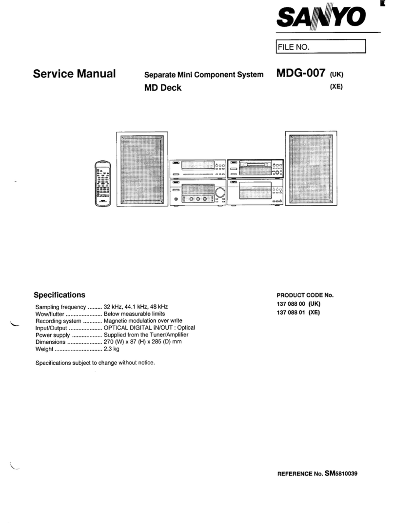
Sanyo
Sanyo DC-MV20 User manual

Sanyo
Sanyo DC-DA370 User manual

Sanyo
Sanyo DC-DA 1400M User manual

Sanyo
Sanyo DC-MCR80M User manual