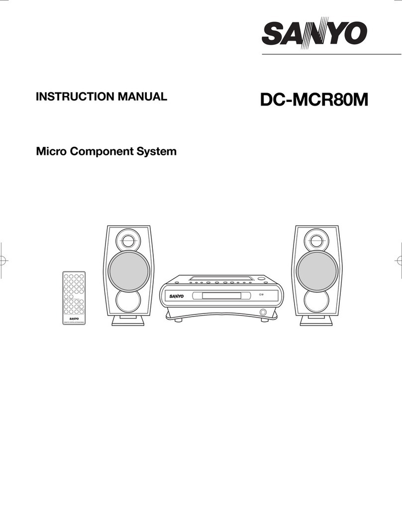
Sanyo GCD2000 User manual

m
FILE NO.
Service Manual
Specifications
Tuner section
Fre~uency range .....
Sensitivity ............
Cassette deck section
Track system . . . . . . . . .
Frequency response ....
Signal to noise ratio . . . .
Wow and flutter .......
Tape speed ..........
Fast forward /
rewind time
CD player section
Channels ............
Sampling frequency . . . .
Digital filter ...........
D/Aconversion .......
Pickup ..............
Frequency response ....
Signal to noise ratio . . . .
Total Harmonic Distortion
Wow and flutter .......
CD Changer
Stereo Music System
FM :87.5-108.0 MHz (50 kHz
steps)
M.W :531 -1,701 kHz (9 kHz
steps)
FM :20.7dBf (mono)
----
AM :800 uV/m (AM Loop Antenna)
AC bias, .4-track 2-channel stereo
100-12,500 fiz -
50 dB
0.1 50/0 (WRMS)
1-7/8 i.p.s. (4.75 cmk.ec..)
Approx. 110 sec.. (C-60)
2-channel stereo
44.1 kHz
8xOver sampling
Two 16-bit linear D/A converters
Optical 3-beam semiconductor
laser
20-20,000 Hz
96 dB
0.04’% (1 kHz)
Undetectable
Specification sui]ject to change without notice.
.. -.—. ..———.. ..___
PRODUCT CODE
129 385-04
Amplifier section
Output power . . . . . . . . Max. 3.5w x
distortion) 2(at 8ohms, 107o
Input sensitivity /
impedance -. .VIDEO :300mV /50k ohms
Graphic equalizer -.... f6 dB (100 tiz, 1kHz, 10 kHz)
Bass expander . . . . . . . +8 dB (100 f-fz)
Output impedance . . . . SPEAKERS :8ohms
HEADPHONES :8ohms
General section
Power requirements . . . AC :230-240V, 50HZ
Power consumption . . . 31 w
Dimensions (approx.) . . 14.2” (W) X13.9” (H) X15.7” (D)
(360 x353 x399 mm)
Weight(approx.) . . . . . . 17.1 Ibs (7.75 Kg)
RB-X2000 remote controller
Power source . . . . . . . DC :3V6’SUM-3/AAfR6’s battery
Dimensions (approx.) . . 1X62 (W) X6.9” (H) X0.7” (D)
(41 x175 x18mm)
Weight(approx.) . . . . . . 2.0 oz. (63g) (without batteries)
REFERENCE No. SM580037

LASER BEAM SAFETY PRECAUTIONS (CD) —
Do not look directly at the laser beam coming from the Structural Safety Interlock
pickup or allow it to strike against your fingers, skin, This model has adisc chuck lever and top lid. This disc
etc.
Do not apply power if there is abroken part in the laser chuck lever and top lid prevent to expose the laser beam
for users.
output section of the pickup. 1
INVISIBLE LASER RADIATION EXPOSURE TO BEAM IS DANGEROUS CLASS 1LASER PRODUCT I
OUTPUT POWER :0.6 mW MAX WAVELENGTH :790 nm I
..-
‘--- “u!
E!Eiii3“
.- U
4ANDLING THE PICKUP
b.
,’,
. . .
. . .
1. Shipping and storage cautions
a.
b.
The pickup must be stored in aconductive bag
until immediately prior to its use.
Do not drop it or subject it to impacts.
c.
2.a.
d.
-.— .- .
Repair cautions . .. .. . .
When handling the pickup, be careful not to give it
undue force or shock by your hands. Otherwise the
pickup may malfunction or the PCB may be cracked.
The pickup which has been minutely adjusted before
shipment as one part. Never touch and move the
adjusting points and setscrews of the pickup unless
otherwise described in the item of adjustment to
avoid damage.
BEFORE REPAIRING THE CD PLAYER (CD)—
1.
a.
b.
Astrong magnet is used in the pickup.
Do not bring amagnet or other magnetized object
near to it.
Cleaning the lens
*If dust gets on the lens, clean it away by using an
air brush such as used for acamera lens.
●The lens is held in place by aspring.
If the center of the lens is dirty, carefully clean” it
using cotton swab moistened with isopropylalcohol.
Since special coating is made on the surface of the
lens which is made of plastics, do not use other
kind of alcohol and cleaning fluid to prevent
damage to the lens. Also, be careful not to bend
the lens spring when cleaning. .. ...
.:..
.......
.,.
Preparations
Many ICS, LSI and the Pickup (laser diode) are
used in the compact disc player. These
components are sensitive to static electricity, and
might be damaged by static electricity or high
voltage, so particular care should be taken
regarding this point.
Many precision components and the lens are used in
the pickup.
Never attempt to make repairs, or to store parts,
where the temperature or humidity is high, where
magnetism is strong, or where there is much dust.
2. Notes regarding repairs
a. Be sure to first disconnect the power plug before
attempting to replace any component.
b. All tools, instruments, etc., used for measuring must
be grounded.
Grounding can be accomplished by using a
conductive metal sheet on the work bench.
c. To prevent AV leakage of the soldering iron, ground
its metal part.
d. Repair personnel must be grounded.
!EFORE USE OR TRANSPORTATION
Before use
1. Carefully unpack the unit 3. Remove the sheet and tape which secures the
2. Remove all packing material from around the unit. carousel. ,..
4. Attach the dust Cover.
●-1- -.

i
.. s
BEFORE USE OR TRANSPORTATION
Before transportation 4. Remove the dust cover.
1. Remove all discs from the trays. 5. Attach the transportation sheet and tape.
2. Turn off the power. 6. Confirm the power off when after base mechanism is
3. Disconnect the AC power cord, patch cords and chucking. (Displayed the “NO DISC”)
remote control cord.
ADJUSTMENT (TUNER)
.Adjust the intermediate frequency of AM and FM to the frequency of ceramic filter.
.Use aplastic screwdriver for adjustment. SG RF Level :75 ohm Open voltage
1. FM BAND Antenna: 75 ohm Direct, Modulation :1 kHz, Dev. :~7?5kHz (mono /stereo) .f40kHz (main)
~6.75kHz(pilot)
PARTS STANDARDS
Usually, not to alignment for
T2201 presetted. See note ~
Confirm voltage isabout
L2 104 1.1-1 .3V.
STEP ITEMS TUNING
FREQUENCY INPUT COND~
MEASURE ON OUTPUT CONDITION
INPUT IMEASURE OUTPUT
I1IF(V CURVE) 10.7 MHZ IFSweep generator
.—
t-
87.5 MHz
2COVER
108.OMHZ
DC Voltmeter TP202(H)
—-— TP201(E) Confirm voltage is below 8.5V
..’,
L2102
L2103
II90.OMHZ TP211(H) VTVM TP233(L)
TP212(E) Oscilloscope TP234(R)
TP235(E)
FM SG
(about 8dB) AF output maximum
3TRACKING
FCT201
T2202
IDigital Voltmeter TP203(H)
TP204(E) OV tO.05V. See note@
=H
4Ov
5Vco 98.OMHZ FM SG
(66dB)
-.
SVR23 19KHz k50Hz See note@
L-R. R-L :Minimum
..e..-
---—
6SEPARATION DEV(MAIN) =f40kHz
Confirm stereo indicator lights
up.
Stereo
7Sensitivity 98.OMHZ FM SG
Note :~Confirm IF waveform maximum and symmetric as shown below. If IF waveform is NG, please adjust T2201 as it
become GOOD. A--’dX-”-+=L-
GOOD NG NG
.
,. ,.,
,.
@Be careful so that digital voltmeter earth may not be in contact with other measuring equipments earth.
@Adjust in the modulation off after the stereo indicator light on.
2. AM BAND (No alignment)
F
Antenna :IRE Loop, Modulation :1000Hz 30?
STEP ITEMS
1COVER
2TRACKING
=-l=== 3N OUTPUT CONDITION
INPUT MEASURE OUTPUT
I
-Confirm S8.5V (about 7.7V)
531kHz --—
1701kHz
Digital Voltmeter TP202(H)
-—--- TP201 (E)
+
output :Maximum
----- Adjust to near
the effective sensitivity.
--.-—
LOOP VTVM TP233(L)
Oscilloscope TP234(R)
ANT TP235(E)
+
603kHz AM SG
1404kHz (about 80 dB)
-“”EIConfirm auto tuning stops
----.-
LOOP Digital Voltmeter _
ANT
-2-

ii
.- S
PARTS LOCATION (TUNER)
TUNER P.C.B
TP202 TP201
C2102
~~e ‘J
El
—
T2201
)’
J460C
TP204
I!Qil
o3432
T2202 J43& IIIL
J430
TP235 -TP234
TP233 F
..
.’. .
. . . ..
ADJUSTMENT OF DECK
Tape Speed Adjustment
Connect the FREQUENCY COUNTER to TAPE OUT.
1. Insert the test tape(MTT-1 11N, etc. :3000 Hz) into the DECK 1. Note :Set the test tape near the tape end
STOP button, and eject the test tape.
test tape(TCW-211, etc. :1500 Hz) into the DECK 1.
tape (C-60 Blank tape) into the DECK 2.
REC button of DECK 2 and press the DECK 1/2button.
FWD PLAY button. Both mechanism become normal speed dubbing.
high speed test pin to the high speed position.
2. Press the FWD PLAY button.
3. Adjust SVR401 so that afrequency ~-ounter reading of 3000 t5HZ %obtained: ‘“- ““-
4. Press the
5. Insert the
6. Insert the
7. Press the
Press the
8. Short the
(The mechanism is high speed dubbing.)
9. Confirm that afrequency counter n%ding of 3000Hz t10% (300 Hz) is obtained.
PARTS LOCATION (DECK)
DECK AMP Pc.6 - -
Ell
SVR401
I1
-3-
,:..
....:,.

MEASUREMENTS OF TORQUE
ITEM TAKE-UP TORQUE iBACK TENSION PULLEY TENSION
PLAY :TW2111 (FWD) PLAY: TW2111(FWD) Driving power cassette:
Test cassette PLAY :TW2121(REV) PLAY :TW2121(REV)
I
TW-2412(FWD)
F.FWD/REW; TW2231 REW:Torque Gauge TW-2422(REV)
PLAY 30- 60gr.cm 2.0- 4.5gr.cm >60g
F.FWD 55- 120gr.cm
REW 55- 120gr.cm I
REPLACEMENT OF HEADS
TAPE ‘“B”” TAPE ““A””
BROWN PINK PINK
RED
FROM 6P CONNECTOR BROWN
(FROM 9P CONNECTOR) FROM 9P CONNECTOR BLACK
APPLVCEMEDINETOFIX APPLVCEMEOiNETO FIX
HOW TO CD PICKUP -..
f?
f?
?1?
,. .— -..-..
L
4!!3
=a2F
(SHORT)
!
/
L
4!!3
=$z!!16
I(OPEN )
CD MECHANISM DESCRIPTION
1. Sensor &Switches of CD Mechanism
1.
2.
.’
PHOTO SENSOR :
PSOI 1(PSOO1):Detection stop of DISC TABLE, position for reduce of DISC speed and music No.
SWITCHES :
SWI (with PICKUP Mechanism) :Detect limit position of the PICKUP.
SW2(S015 =S002) :Detect complete of chucking for the DISC.
SW3(SOI 4=S001 ):Detect complete of release of chucking for the DISC.
-4-

CD MECHANISM DESCRIPTION
2. Drive Control of DISC TABLE &PICKUP Mechanism
ISW2 ON ICCW: Counter Clock Wise CW :Clock
INPUT+
%“0
.FNO
b1
2==
No. DETECT NO
YES
PAST AT 70mSEC NO
YES
*
+
YES
MOTOR CCW -0
RETURN
}MOVEMENT DIRECTION OF SENSOR
1.
2.
3.
4.
5.
Unless 10 msec. <tl, the microprocessor is not able to detect it.
(a). If the turntable is rotating too slowly (t2 >70 msec.), or
(b). if the turntable is rotating too quickly (tl <10 msec., the turntable will continue to turn (it will not stop rotating).
If, after the slit for the last disc number (@ in illustration) has passed, the next slit is not encountered for more than
70 msec., the next slit is detected and used as the stop position.
If the turntable is rotating too slowly (t2 >70 msec.), the slits between @– and @~~ ~e-mistaken for stop positions.
,...
The base mechanism will rise at these positions and bump into the turntable.
When the base mechanism is rising or lowering, the motor stops when switch 3is not on if 16 sec.. have passed.
Malfunction.
When the base mechanism is rising or lowering, the next disc is selected or switch 3turns on 4 times when switch
is not on if 16 sec.. have not passed.
The control keys have no effect when the base mechanism is rising or lowering.
Action of CD Mechanism
1)DISC SKIP
-._. .. .-
37
21
-5-
Figure 1
2
... .
,( . . . .
,,, ,,,
. ..

ii
.. ●
Figure 1shows what the inside of the unit looks like when adisc is in play. Pressing DISC SKIP button at this point
causes the spindle motor to stop (disc rotation stops) and the shaft of the sled motor to turn counterclockwise. This
causes the pickup to move in direction D. when the position where the limit switch (SW1 )turns on is reached, and the
sled motor stops. Simultaneously, the spindle of another motor (39) starts to turn counterclockwise, causing the gear
(31 )to move in direction F. This causes another gear(31 )to engage yet another gear (27), making the second gear (27)
rotate counterclockwise. The cam portion (@) of another gear (27) is linked to the boss (@) of the lever (44), so the ro-
tation of the above mentioned gear (27) causes the lever (44) to move in direction J. The slide (45) linked to the boss
(@) moves in direction L(the switch (SW2) turns off), and the bosses (@ and @) of the sub-chassis (21) disengage the
parts (@and @) of the slide (45) that they had been linked to. This frees the sub-chassis (21) so that it can move
downward
.,.
.
. .
,..
.. . .
.,,..
Figure 2
AS shown in Figure 2, one of the gears (28) is equipped with acam. One boss (@) of the sub-chassis (21) en9a9es it
while the second boss (@) provide; ”rotating support for the p’anel fdp (See 82 “in ‘“CD Turntable Exploded V!ew).
Therefore, when the gear (28) rotates, the sub-chassis (21 )moves in direction G(downward) as shown .
Figure 1shows how the assembly looks when the gear (28) has turned, causing the sub-chassis (21) to move down-
ward and the slide (45) to move in direction L.
At the same time, Figure 1shows the switch (SW3) turns on, causing the shaft of the motor (39) to switch from coun-
terclockwise to clockwise rotation. This causes the gear (31) to turn in direction E, engaging another gear (37). The
second gear (37) turns clockwise. As shown in Figure 3, this gear (37) engages the inner gear (@) of the turntable
(70), so the turntable (70) turns in aclockwise direction.
. ... .. .-- .—
70
~3\
J-
r
31
.~
,STOP
Y
‘Psol 1
POHTO
SENSOR
\
DISC No.
STOP
.
,’
-6-
Figure 3

.-
AS the turntable (7o) rotates, the sensor (PStM 1)detects the slits (@ and @) in it. The first slit (@) is used tO detect the
disc number and the second slit (@) to detect the stop position. When the senmr (PSO11 )detects the specified disc
number*, the shaft of the motor (39) begins to turn more slowly, and the turntable Sows down. When the next slit (@) is
detected, the rotational direction of the shaft of the motor (39) again reverses and Nbegins to turn counterclockwise. As
shown in Figure 1, this causes the gear (31} to turn in direction F(Figure 1). As shown in Figure 1, another gear (28)
then starts to turn and, in the reverse of the operation described above, the sub-chassis (21) rises and the slide (45)
moves in direction K,eventually ending up as shown in Figure 5.
At this point, the switch (SW2) turns on and the motor (39) stops. At the same time. the sub-chassis (21) is locked in the
lowered position by the slide (45).
Note :●Specified disc number ;DISC SKIP button :the next disc number.
39
&s
37 35
1
,- .1
(!! ~
,. )
.
Y
-\
\l/
31
Figure 4
2)POWER ON (When AC Cord is First Plugged In)– Refer to Figures 1-5-
. .
Basic operations :The turntable rotates to the disc number 1po&ion, %d check stet astet the base mechanism takes
. .... ..
figure 5
1,
2.
place.
If the switch SW3 is not on :
The spindle of the motor (39) rotates counterclockwise, lowering the sub-chassis (21 ). When the switch SW3 turns
on, the rotational direction of the motor shaft changes to be clockwise. This causes the turntable (70) to rotate. When
the sensor (PSO11 )detects the disc 1stop position, the motor (39) switches back to counterclockwise rotation, rais-
ing the sub-chassis (21 )and performing checking. When another switch SW2 turns on, the motor stops.
If the switch SW3 is on :
The spindle of the motor rotates-clockwise. This causes the turntable (70)-to rotate. When the sensor (PSO11 )de- . .,
(. .:
tects the disc 1stop position, the motor (39) switches back to counterclockwise rotation, raising the sub-chassis (21 )
and performing checking. When another switch SW2 turns on, the motor stops.
3)POWER OFF (MANUAL Switch Off)
Basic operations :1. If the motor (39) was stopped, it remains so.
2. If the motor (39) was running, then the motor stops.
..,’.
-7-

.. ,
STANDARD MAINTENANCE FOR CD
1. Applying Grease and Grease point
1)DISC Table (Top
2)CD Mechanism Block A
.“..
.,. ,
Note: S4W4G13EASE SG-7 =SANYO Type N0.HZGSNGROSG7
FLCW OIL 949P =SANYO Type No. HZOFOIL949P
Note: MC-GREASE EM50L =DOW CORNING Type No.
MOLYKOTE EM-50L
Attsr Insert gear lever and special waskf, SPPIY ip@ o
MC-grease EM!50L to 1/3 length portion of shaft APPLY SANGREASE
WASHER tSG-7
APPLY
-%
MC-GREASE EMSOL ‘“’
GEAR LEVER VIEW -A
&
&’
APPLY MC-GREASE EM50L
GEAR ALL AROUND
. ..... $? ‘?.
-. -. .... ... ......
I
-1
1LY SANGREASE
SG-7
I
.. .-.
r--l
After
Lever
Note :After inserting the gear lever and the special washer into the shaft, apply MC-Grease EM50L to the upper 1/3
of the shaft as shown in view-B above.
-8-

3)CD Mechanism Block B
APPLY SANGREASE SG-7
7Ir&
APPLY
FLOIL OIL 949P
(LITTLE )
-...
4)CD Mechanism Block C
APPLY
MOLYKOTEEM-50L .=
GEARALLAROUNO
..
5)CD Mechanism Lead Retainer
.,—
r%
pyu
‘L_7 ‘“-
IORANGEI& 0
@!$
x
-9-
.,..
.’: ..,...
.’,.:.
.,. ,,,
,’. .

i
.+ ●
SERVICE MODE
Specifications
To enter any service mode other than timer debugging, first simultaneously press the CD Memory key and BAND keys on the
set when Power on. This accesses the service mode entry state. Now press one of the buttons on the set to enter aservice
mode. As the service mode entry state is discontinued after 1second elapses. (the system will enter aservice mode only if
the next key is pressed within one second.) And more, press the 2keys when reset start to enter aCD Tracking Balance
mode.
1. Checking the key input signal connections
OEnter this mode by pressing the MEMORY(TUNER) key during the service mode entry state.
OThe entire LCD goes out once this mode is entered.
OIn this mode, as keys on the set are pressed segments on the LCD corresponding to each key on aone-to-one basis
come on (i.e. the lit portiorls gradually increase). (Refer
OPress the MODE key to exit this mode and return to the
KEY DISPLAY KEY
1,I
TU/BAND IREC IIPLAYIPAUSE
TU/MEMORY ITIMER It STOP
TWMODE x
TUNING/UP SLEEP +
TUNINGIDOWN CONT
VOUUP TIME -
%i=E%F
CD/REPEAT REPEAT II
DISC 1
to Table 1.)
normal mode.
1
DISPLAY !
a
DISC
TRACK
ALL
SIDE B
RANDOM
H
1OF CALENDAR I
KEY IDISPLAY I
DISC 55OF CALENDAR
EDIT EDIT
(PHONO) 12 OF CALENDAR
CD 13 OF CALENDAR
TUNER I14 OF CALENDAR I
TAPE 15 OF CALENDAR
VIDEO ➤OF. CALENDAR
-. “— ..-----
~:Releases the key checking mode and returns the set to the normal mode. ..... .
TABLE 1:CORRESPONDING KEYS AND DISPLAYS IN THE KEY CHECKING MODE
COMPU
SLEEP
WAKE I
LEVEL
TER RECL
,;–/–/%?/6
/1/e/F/c
-f
TIMERREC
wDISC’ST
WIDE CLOCK INTRO RANDOM OFF SIDEA
TRACK AUTO MONO FADETIMEEDIT
REPEAT P
3456789101112131415 ~oNEALLcoNT
FIGURE 1: LCD (LIQUID CRYSTAL DISPLAY)
2. Checking LCD connections
●Enter this mode by pressing the REPEAT key during the service mode entry state. (See nOte.)
●The entire LCD goes out once this mode is entered.
.in this mode, one segment of the LCD ]ights each time the REPEAT key is pressed.
●Press the MODE key to exit this mode and return to the normal mode.
-1o-

ii
.. ●
SERVICE MODE
3. CD tracking balance adjusting mode
“Enter this mode by pressing the PLAY/PAUSE key during the service mode entry state.
.If the power is off and when the reset started, by pressing CD MEMORY key and TU/BAND key with simultaneously, and
enter this mode by power on.
.In this mode, the tracking balance adjustment state (tracking is off) is automatically entered. If the PLAY key is pressed in
this state, the tracking servo is turned on and playing is begun at the present position. Therefore, the readout on the
display at the time playing is begun indicates the initial position of the pickup (i.e. the position of the limit switch).
.In this mode, the tracking balance adjustment state can be entered by pressing the MEMORY key during playing.
Pressing the PLAY key in this state turns on the tracking servo and causes playing to begin.
.Turning off the power releases the CD tracking balance adjusting mode.
4. CD operation display mode
“Enter this mode by pressing the STOP key during the service mode entry state.
“In this mode, when CD function are used, displays like those shown in Table 3(which represent CD
operations different than normally displayed) appear in the LCD track number display.
“In this mode, the calendar numbers shown in Table 4come on when an error occurs in CD operations, at which time the
track number and calendar displays become fixed at their current readouts.
sThis mode is released when press the MODE key or power is turned off. ‘.
..,’.
DISPLAY
00
OPERATION
Focus search has been begun IDISPLAY OPERATION
172 L-point access (CWD64 track jump)
01
02
03
Focus search has been begun
Waiting for focusing
I73 IL-~oint access (REV16 track jump) I
I74 IL-point access (FWD16 track jump) I
Focusinq I75 L-point access(REV1 track jump)
76 IL-point access has been completed
04
05
Spindle kick is in progress
Both CLV and tracking are ON I80 Pausing has begun J
06 Both CLV and trackin~ are ON .I83 Pause (REV16 t~ack jump) . .. . 1
0-
22
FOCUSsearch has been completed (success, failure)
Pick return (internal direction) is in progress
84 Pause (FWD16 track jump)
85 Pause (REV1 track jump)
86 Pause (trace)
23
2-
Pick return (external direction) is in progress
Tray closing (pick return) has been completed 90 Music access has begun
91 Music access (high-speed access has begun)
92 Music access (high-speed access is in progress)
30 Spindle brakinq has bequn
31
32
Spindle braking is in progress
Pick return is in Drooress 93 Music access (high-speed access has been completed)
96 Music access (REV64 track jump)
97 Music access (FWD64 track jump)
1..
. . .
..’
3-
40
Spindle braking and pick return have been
completed
Fast forwarding is in progress 98 Music access (REV16 track jump)
99 Music access (FWD16 track jump)
9A Music access (final stage)
Rewindinq is in proqress
50
51
Playing has begun
Playing is in progress (break in the sound) 9- Music access (finai stage)
AO Base Mechanism go down has begun
A2 Turntable rotation has begun
52 Plavinq is in proqress (skip return o~eration)
60 TOC reading has been begun
TOC reading is in progress
61 A7 Turntable rotation low speed
A8 Base Mechanism rising has begun
A9 Base Mechanism chucking has begun
62
6-
TOC reading is in progress
TOC reading has been completed (success/failure)
70 L-~oint access has been bequn IA- Base Mechanism chucking has been completed
71 L-point access (REV64 track jump)
TABLE 3:DISPLAYS DURING THE CD OPERATION MODE
-11-

i
.. ●
SERVICE MODE
INUMBER
1=
1
2
3
R-
STATE OF CD ERROR
Focusing is not possible in focus search.
The sub-code is not input during disc startup.
TOC cannot be read.
The focus was lost while the servo was on (during playing, etc.).
The sub-code is not input while the servo is on (during playing, etc.).
TABLE 4:DISPLAY OF CD ERRORS
CD ADJUSTMENT
Electrical Adjustment IOK
So far we have presented explanations regarding compact
disc player handling, notes prior to repair, handling the pickup
and disassembly of the unit. Be sure to carefully read these
instructions before making any adjustments. “r;:D–M{’o-’cope
Preparations for Adjustments BAND PASS FILTER
Measuring instruments, tools and filter (4) Oscillator (400Hz, 300mV RMS)
(1) Test disc. :YEDS 18 (Sony) (5) Frequency Counter (5MHz ;or more)
(2) Oscilloscope :SS5711 (1OMHZ or dual phenomenon) (6) Screw drivers (non-metalic) for adjustments
or Memory scope :DSS6521 (Storagescope) (7) Band Pass Filter
(3) Digital voltmeter (Input impedance 1Mohm or more) (8)AC Voltage Meter
Notes :a.
b.
c.
1. Initial
The adjustments can be using the equipment produced by other manufactures provided that the
performance of that equipment corresponds to that of the above listed models.
Use a10:1 probe for observing signals on the oscilloscope and storage scope.
Test disc is subject change without notice.
-. ., .— .. __. .- ... .. .
set
1. Set the SVRI 1to the mechanical center position as the initial position of as shown in figure below.
TF
SVR1l TP1 RF
TRACKIW R4LANCE ~TP2 FE SPINDLE ~
_TP3 TE SLED MOTOR
TP4 ‘3WI LIMIT SW
CN106
~— -. L
Ll–
II /’P
TO SYSCOiU mssc32r4
TO PICK UP (C%86) (c%%
2.
1.
2.
3.
4.
Tracfdng Balance Adjustment (SVRlfl)
Connect the oscilloscope to TP3 (l_fE) and
(GND.).
COMAIN PCB
E
TPIO!IRF)
1P102(FE)
TPlO]llE)
1PU14@NO)
‘a
Sw?ll
TP4 5. Adjust SVR11 so that the TE (Tracking Error) signal
waveform of TP3 on the oscilloscope is vertically sym-
Turn on the power of the unit. Insert test disc .metrical relative to OV. (See figure next page)
Playback the test disc. Note: If this adjustment is imperfect, the sled motor (pickup
Continuously press the forward search ~or back- sencling motor) will run and normal play will be dis-
ward search 44 button to do it. abled.
-12-

ii
.- *
2D ADJUSTMENT
u--vim –-T%s
TP 1
(RF)
Ov
,. .
..l...l.. i.....
1“1”11 I
It’wtw’-”io
v
TP3
(TE)
+SEARCH SEARCH *
Other Adjustment of Tracking Balance (SVRII)
Set the service mode(CD tracking balance adjusting mode).
.Enter this mode by pressing [he PLAY/PAUSE key during
the service mode entry state. Pressing the PLAY/ Pause
key in this state turns on the tracking servo and causes
playing to begin. (See service mode)
Connect the oscilloscope to TP3 (TE) and TP4 (GND).
Adjust SVR11 so that the TE (Traverse) signal waveform of
TP3 on the oscilloscope is vertically symmetrical relative to
OV. Or may adjust SVR 11 so that the DC voltage :(Peak
Hold Level) -(Bottom Hold Level) of the traverse signal is
OV. (See figure right side)
If it were not for obtain waveform at the right figure, repeat
item 2-1 -2-3. —.
)
..
L
1.
!.
1.
2
-.
3.
_._. -1
11]+ 500”s 111
.---r .,, ,
,
TP1
(RF)
,:,..
:.’. .:
t.+J-I--4-A..-I -’4-+---i
TP3
(TE) Ov
4+ SEARCH
.-. —----- .....
Focus Gain Confirmation
Connect the storage scope to TP2 (F.E :Focus Error)
through the Band pass fiiler. (See BPF Figure)
Turn on the power of the unit.
Playback the test disc.
4. Set the output of AF oscillator to 400 Hz, 0.5V rms and
connect to pin 24 (IC1 01) through the resistor :120k ohms.
5. Confirm so that the voltage of the F.E signal waveform on
the storage scope is 0.5V p-p, t3db by through BPF.
‘If this CONFIRMATION is imperfect, become weak the mechanical shock, inferior playability, and can not playback the Disc.
,.” ,.
....’..
-....
AF (XCII IATOR MAIN PCB OSCILLOSCOPE or STORAGESCOPE
v1BAND PASS FILTER
TP2 I
,.-.-, Iv
.----- -------
, f
$. Tracking Gain Confirmation
1. Connect the storage scope to TP3 (T.E) through the Band
pass filter. (See BPF Figure).
2. Turn on the power of the unit.
3. playback the test disc.
4. Set the output of AF oscillator to 400 Hz, 0.5V rms and
connect to pin 14 (ICI 01) through resistor 47k ohms.
5. Confirm so that the voltage of T.E signal waveform on
storage scope is 0.5V p-p, t3db by through BPF.
the
.. ............... . ...
. ... . . . . . .
“Ifthis CONFIRMATION is imperfect, become weak the mechanical shock inferior playability, and can not playback the Disc.
AF OSCILLATOR MAIN PCB OSCILLOSCOPE or STORAGESCG?E
47K BAND PASS FILTER
400Hz
0.5V rms TP3
PIN 14 (TE) -
=u
-13-

i
.. ●
PARTS LIST
PRODUCT SAFETY NOTICE
Each precaution in this manual should be followed during servicing. Components identified with the IEC symbol ~in the parts list
and the schematic diagram designate components in which safety can be of special significance. When replacing acomponent identi-
fied &use only the replacement parts designated, or parts with the same ratings of resistance, wattage or voltage that are desig-
nated in the parts list in this manual. Leakage-current or resistance measurements must be made to determine that exposed parts
are acce Dtab[v insulated from the SUDDIV circuit before returnina the Droduct to the customer.
CAUTION: Regular type resistors and capacitors are not list. To know those values, refer to the schematic diagram.
N.S.P :Not available as service parts.
ACKING
Ref. No.
&ACCESSORIES
Part No.
614 244 7208
614 244 7215
614 240 7363
614 240 7370
614 176 7024
614 180 4644
614 176 3231
614 244 7277
614 243 5472
614 232 6671
614 234 5511
614 231 6832
CABINET&CHASSIS
Ref. No.
1
2
3
4
5
6
7
8
9
10
11
12
13
14
15
16
17
18
19
20
23
24
25
26
27
28
29
30
Part No.
614 239 4281
614 216 7083
614 241 7171
614 244 6966
614 129 1901
614 112 3509
614 240 6281
614 240 6304
614 241 5504
614 241 5528
614 220 6690
614 239 6063
614 240 6397
614 239 4403
614 239 4410
614 125 0830
614 069 0385
614 218 0051
614 194 9239
614 239 4618
614 240 8926
614 232 4677
614 216 9261
614 216 9346
614 208 0986
614 240 2702
614 240 2719
614 216 9063
614 216 9117
Description
INNER CARTON, PROO
SINGAPORE
INNER CARTON,PROO MALAYSIA
PAO,BOTTOM
PAD,TOP
INNER POLYE COVER,SET
PROTECTOR SHEET,SET
INNER POLYE COVER,ACCESSORi
INSTRUCTION MANUAL
NOTICE,CD MECHA PROTECT
ANTENNA
LOOP ANTENNA,AM ANT
LABEL,SAFETY,LASER CLASS
Description
CABINET,%OTTOM
ASSY,FOOT
PANEL,REAR,PROD SINGAPORE
PANEL,REAR,PROD MALAYSIA
FIXER,AC CORO
HINGE,COVER,DUST
ASSY,PANEL,FRONT
ASSY,PANEL
ASSY,LID,CASSETTE
ASSY,LID,CASSETTE
WINDOW,-EQ
WINDOW,VOL.
WINDOW,FUNCTION
PANEL,SIDE, L
PANEL;SIDE, tl-
CUSHION,HINGE
GEAR ASSY
SPRING,WIRE,LID,CASSETTE
BRACKET,MECHA KNOB
BRACKET-E,FRONT-SIOE (R)
BRACKET-E,FRONT-SIDE (L)
SHEET,CD PANEL,TOP
BRACKET-E,DECK PCB FIX
SPRING,PLATE,REC
CUSHION,LEAD FIX
BRACKET-M,FRONT-SIDE (R)
BRACKET-M,FRONT-SIDE (L)
BUTTON, MECHA BUTTON (STOP.
ETC)
BUTTON,MECHA BUTTON(PAUSE)
Ref. No.
31
32
33
34
35
36
37
38
39
40
41
42
43
‘IXING P
Ref. No.
Y1 -
Y2
Y3
Y4
Y5
Y6
Y7
Y8
Y9 -
;LECTRI(
Ref. No.
51
52
53
54
55
56
-14-
Part No.
614 216 9124
614 228 0218
614 239 4519
614 239 4526
614 242 0423
614 242 0430
614 239 4557
614 240 2344
614 242 0447
614 242 0454
614 240 6441
614 220 6737
614 240 6274
614 212 8343
,RTS
Part No.
411-021..6603
411 021 3503
411 021 1806
411 021 6405
411 133 0902
411 001 3905
411 028 2905
411 022 2802
4il 154 4200
,L PARTS
Part No.
fi614 023 2912
614 217 3732
A614 244 5761
~614 245 8389
Li!i614 245 8440
A423 016 9308
614 244 7543
614 244 7550
614 244 7567
Description
BUTTON,MECHA BUTTON (REC.
ETC)
BUTTON,BASS.OUB.
BUTTON,POWER
BUTTON,BANO.MEMO
BUTTON,PLAY
BUTTON,REPEAT
BUTTON,SKIP
BUTTON,RANDOM .EDIT
BUTTON,TUN.PRESET
BUTTON,VOL
BUTTON,FUNCTION
KNOB,SLIDE,EQ
ASSY,COVER,DUST
LABEL,LASER SAFETY
Description
SCR S-TPG 81N 3X8,PANEL
SIDE &TOP
SCR S-TPG BIN 3X1O,REAR
BOTTOM &SOCKET/GEAR ET
SCR S-TPG BIN 2.6X1O,FRONT
BRACKET-M/KNOB BRACK
SCR S-TPG BIN 3X8,DECK
MECHA FRONT SIDE &BOTTOM
SCR S-TPG BRZ+FLG 3X6,AMP
PCB HEAT SINK IC
SCR S-TPG BIN 4X6,TRANS
SCR S-TPG PAN 2X4,DECK
BRACKET-E
SCR S-TPG FLT 3X1O, BASS
XPANDER &POWER
SCR S-TPG PAN+FLG 2X6,LUG
Description
POWER CORD
HEAT SINK
POWER TRANS
PCB,PT 1
PCB,HEADPHONE STOPPER
FUSE,250V 0.2A (F901)
ASSY,CONNECTOR-S,6p(CN103)
ASSY,CONNECTOR-S,8P(CN1O5)
ASSY,CONNECTOR-S, 13P(CN104)

PARTS LIST
RONT P
Ref. No.
71
CN251
CN252
CN253
CN254
CN255
CN503
CN504
CN505
CN506
CN507
CN601
CN602
CN603
CN604
CN605
CN606
CN607
CN608
D2501
or
or
D2502
02503
or
or
D2504
or
or
D4402
D4403
D4404
D4405
D4411
D4412
D4413
D4414
04415
D4420
or
D4421
or
D4422
or
D4430
or
D4431
or
D4433
or
D4440
or
D4490
or
IC251
IC501
IC502
IC503
IC601
IC900
IC901
L2501
LCDO1
PL251
:.BOARD ASSY
Part No,
614 242 4896
614 035 4997
*14 035 4935
614 244 1602
614 244 1596
614 035 4928
614 244 0155
614 244 0131
614 211 3233
614 244 0148
614 211 2991
614 240 2450
614 226 9978
614 020 6616
614 020 6579
614 020 6579
614 020 6586
614 020 1222
614 035 4973
407 007 9904
407 012 4406
407 012 5809
407 005 4505
407 007 9904
407 012 4406
407 012 5809
407 007 9904
407 012 4406
407 012 5809
407 036 9203
407 036 9203
407 036 9203
407 036 9203
407 039 5905
407 039 5905
407 039 5905
407 039 5905
407 039 5905
407 005 4505
407 013 7109
407 007 9904
407 012 4406
407 007 9904
407 012 4406
407 007 9904
407 012 4406
407 007 9904
407 012 4406
407 007 9904
407 012 4406
407 005 4505
407 013 7109
407 007 9904
407 012 4406
410 146 1203
409 003 9308
409 053 0409
409 018 4909
409 003 9308
409 039 9204
409 020 0906
614 028 4256
614 239 1723
614 045 9661
Description
!USY,PCB,FRONT
SOCKET,1OP
SOCKET,4P
ASSY,CONNECTOR-S
IISSY,CONNECTOR-S
SOCKET,3P
SOCKET,TO DECK 9P
SOCKET,TO DECK 4P
SOCKET,TO MAIN 5P
SOCKET,TO MAIN 6P
SOCKET,TO MAIN 2C
PLUG,13P
PLUG,1OP
SOCKET,9P
SOCKET,5P
SOCKET,5P
SOCKET,6P
SOCKET,3P
SOCKET,8P
DIOOE GMAO1
DIODE 1SS133
DIODE 1SS176
DIODE DS442X
DIODE GMAO1
DIODE 1SS133
DIOOE 1SS176
DIODE GMAO1
OIODE 1SS133
DIODE 1SS176
LED SLP-138C-51-B,CD
LED SLP-138C-51-B,TUNER
LED SLP-138C+51-B,TAPE
LED SLP-138C:51-B,VIDE0
LED SLP-738F-51-B,LEVEL 1
LED ’SLP-738F-51-B,LEVEL 2
LED SLP-738F-51-B,LEVEL 3
LED SLP-738F-51-B,LEVEL 4
LED SLP-738F-51-B,LEVEL 5
DIODE DS442X
DIODE 1S2473
OIODE GMAO1
DIODE 1SS133
DIOOE GMAO!
DIO~E 1SS133
DIODE GMAO1
DIODE 1SS133
DIOPE GMAO1
DIODE 1SS133
DIODE GMAO1!
DIODE 1SS133
DIODE DS442X
DIODE 1S2473
DIODE GMAO1
DIODE 1SS133
IC UPD75306GF-225-3B9
IC BU4051B
Ic TC9153AP
IC LA6458S
IC BU4051B
IC NJM78L05A
IC LB1403N
FILTER
LCD
LAMP 12V 70MA
Ref. No.
‘L252
]4401
)4402
)4410
)4411
J4412
24413
24414
]4415
24417
24418
24419
24420
24421
24422
24423
24501
j4502
24601
24602
S2501
S2502
S2503
S2504
S2505
S2506
S2507
S2508
S2509
S251O
S2511
S2512
s25i3
S2514
S2515
S2516
S2517
S2518
S4402
S4403
S4404
S4405
S4406
S4407
VR501
VR!302
VR503
VR900
X2501
I
;
CD ‘MICC
T
Ref. No.
72
C1301
CN106
CN107
Part No,
614 045 9661
405 011 8609
405 011 8609
405 000 2205
405 000 2205
405 000 2205
405 000 6104
405 000 6104
405 000 6104
405 011 8609
405 000 6104
405 011 8609
405 000 3103
405 000 3103
405 011 8609
405 011 6609
405 011 8609
405 011 8609
405 011 8609
405 011 8609
614. 220 5655
614 220 5655
’614 220 5655
614 220 5655
614 220 5655
614 220 5655
614 220 5655
614 220 5655
614 220 5655
614 220 5655
614 220 5655
614 220 5655
’614 220 5655
614 220 5655
614 220 5655
614 220 5655
614 220 5655
,614 220 5655
614 220 5655
614 220 5655
614 220 5655
614 220 5655
614 220 5655
614 220 5655
614 239 3888
614 239 3888
614 239 3888
614 239 3871
614 215 5561
614 239 4656
614 240 8940
614 244 9684
’614 241 0996
Description
LAMP
TR 2SC1740S-S
TR 2SC1740S-S
TR DTA144ES
TR DTA144ES
TR DTA144ES
TR DTC144ES
TR DTC144ES
TR 0TC144ES
TR 2SC1740S-S
TR DTC144ES
TR 2SC1740S-S
TR DTC114ES
TR DTC114ES
TR 2SC1740S-S
TR 2SC1740S-S
TR 2SC1740S-S
TR 2SC1740S-S
TR 2SC1740S-S
TR 2SC1740S-S
SWITCH,TACT,FM TUNE BANO
SWITCH,TACT,MEMORY
SWITCH,TACT,MODE
SWITCH,TACT,TUNING UP
SWITCH,TACT,TUNING DOWN
SWITCH,TACT,PRESET UP
SWITCH,TACT,PRESET DOWN
SWITCH,TACT,PLAY/PAUSE
SWITCH,TACT,STOP
SWITCH,TACT,F.REW
SWITCH,TACT,F.FWD
SWITCH,TACT,DISC SKIP
SWITCH,TACT,REPEAT
SWITCH,TACT,MEMORY
SWITCH,TACT,RANDOM PLAY
SWITCH,TACT,INTRO SCAN
SWITCH,TACT,EOIT
SWITCH,TACT,FADE
SWITCH,TACT,CD
SWITCH,TACT,TUNER
SWITCH,TACT,TAPE
SWITCH,TACT,VIDEO
SWITCH,TACT,VOLUME UP
SWITCH,TACT,VOLUME DOWN
VR,SLIDE,GEQ 2X50KB
VR,SLIDE,GEQ 2X50KB
VR,SLIDE,GEQ 2X50KB
VR,SLIDE,BALANCE IOOKSW
RESONATOR,CERAM 4.19MHZ
MOUNT-M
SHEET,MAT
SHEET,FILM
COVER
?0 COMPUTER P.C.BOARDASSY
Part No.
614 242 4902
403 196 9602
614 017 3925
614 017 2102
Descrhtion
ASSY,PCB,CD MICOM
DL-ELECT 0.047F Z
5.5V,BACK UP
PLUG,FOR CTL,13P
PLUG,AC INPUT,3P
-15-

EXPLODED VIEW (CABINET)
Y1
Y1
r. ..
/
v’
Y1
2+5 -

.- 9
~LODED VIEW (CHASSIS)
-17-
,.,.
..
...
.-.,
...”..

ii
. . ●
PARTS LIST
Ref. No. Part No. Description
D2104 407 007 9904 DIODE GMM31
or 407 012 4406 DIODE 1SS133
or 407 012 5809 DIODE 1SS4?6
D2105 407 007 9904 DIODE GNA#l
or 407 012 4405 DIODE 1S!S133
or 407 012 5809 DIODE 1SS%76
D2201 407 007 9904 DIODE GMA$31
or 407 012 4406 DIODE 1SS133
or 407 012 5809 DIODE 1SSX76
D2301 407 007 9904 DIODE GMAQ1
or 407 012 4406 DIODE 1SS133
or 407 012 5809 DIODE 1SS176
D2302 407 007 9904 DIODE GM%J1
or 407 012 4406 DIODE lSS’133
or 407 012 5809 DIODE 1SS176
D2451 407 007 9904 DIODE GM.4@l
or 407 012 4406 DIODE 1SS133
or 407 012 5809 DIODE 1SS276
IC201 409 195 3108 IC LA126!i-AUD
IC202 409 016 9500 IC LA3361.
IC203 409 066 7600 IC LM7001
L2102 614 229 0866 TRANS,RF
L2103 614 229 0873 TRANS,RF
L2104 614 239 7282 TRANS,OSC
L2105 614 028 4058 FILTER 10t4)UH
L2150 614 241 1162 TUNER
L2451 614 028 4256 FILTER 2.i2UH
Q2101 405 114 8506 TR 2SK193-ML
or 405 114 8407 TR””2SK193-LL
Q2102 405 012 5904 TR 2SC19?!23-Y
Q2103 405 114 8506 TR 2SK193+L
or 405 114 8407 TR 2SK193_flL
Q2104 405 012 5904 TR 2SC19Z3-Y
Q2105 405 012 5904 TR 2SC1923-Y
Q2201 405 018 7902 TR 2SC38(KTM-O
Q2202 405 012 2002 TR 2SC181i5-GR
or 405 020 7204 TR 2SC94f&$l-K
j2203 405 001 7001 TR 2SA102S-GR
j2301 405 012 2002 TR 2SC1835-GR
~r 405 020 7204 TR 2SC945$I-K
j2302 405 067 0800 TR RN22UT
Dr 405 078 2404 TR BN1A4F-._.
Dr 405 000 0904 TR DTA114TES
22351 405 067 0800 TR RN220T
Dr 405 078 2404 TR BN1A4P
or 405 000 0904 TR DTAll~S
~2352 405 067 0800 TR RN220Z ‘
or 405 078 2404 TR 8N1A4P
Dr 405 000 0904 TR DTA1143%
~2451 405 114 1804 TR 2SC18K$5(L)-GR
>r 405 114 1903 TR 2SC1815(L)-Y
J2452 405 114 1903 TR 2SC18E6(L)-Y
>r 405 114 1804 TR 2SC18SJ5(L)-GR
J2461 405 012 2002 TR 2SC18E5-GR
)r 405 020 7204 TR 2SC94%%-K
j2702 405 016 2206 TR 2SC28?%3-A
>r 405 016 2305 TR 2SC287%-B
j2802 405 016 2206 TR 2SC28?18-A
)r 405 016 2305 TR 2SC287%-B
~2901 405 012 2002 TR 2SC183.!6-GR
)r 405 020 7204 TR 2SC94&i-K
32465 401 018 1209 CARBON 33 JB l/4W,FLAME
PROOF
3VR23 614 204 1901 SEMI V.R.AOKB
r2201 614 239 7299 TRANS,IF
r2202 614 030 4114 I.F.T
Ref. No.
X2451
or
Part No.
614 240 1118
614 234 0486
614 116 5349
614 117 1029
614 234 1728
:D MAIN P.C.BOARDASSY
Ref. No.
83
CN101
CN102
CN103
CN104
CN105
CN106
IC101
IC102
IC104
IC105
IC106
;:101
Q1102
Q1501
SVR11
X1401
Part No.
614 240 8469
614 017 3840
614 017 3871
614 017 3857
614 017 3925
614 017 2591
614 017 2553
409 245 4802
h409 247 0000
409 248 8708
409 262 1709
409 241 5506
409 192 7109
405 002 0308
405 014 4509
405 014 4509
614 223 1906
614 231’ 2667
REMocoi(149 536-03i
Ref. No. Part No.
I614 236 0132
U-!!Y!!
C)escription
RESONATOR,7.2MHZ
RESONATOR
SHIELD PLATE,SYMBOL SIDE
SHIELD PLATE,PATTERN SIDE
TERMINAL
Description
ASSY,PCB,CD MAIN
PLUG,FOR SENSOR,5P
PLUG,FOR ACT,8P
PLUG,FOR MOTOR,6P
PLUG,FOR CTL,13P
PLUG,FOR DG,8P
PLUG,4P
IC
IC
IC
IC
IC
IC
TR
TR
TR
LA921OM,SSP
LA6524,PICK ACT DRV
LC7866E
LC7883KM
XRA15218F,BUFF
BA15218F
2SA1037K-R,LASER DRV
2SC2412K-R
2SC2412K-R.DAC VREF REG
POTENTIOMETER;SVR1O1 FOR
T.BAL
RESONATOR 16.93MHZ ‘
FLOW CHART
.. .
OUTLINE CHART /~
CHANGER Section
-20-
1Chuckirw “off” mode I
Disc “select” mode
Rotate the turntable and stop
mode with disc appoint
#
[Chucking “on” mode 1
Come up the Base mechanism
w/pickup andd:$ce chucking of
I

.+ w
TROUBLE SHOOTING GUIDE &FLOW CHART
Disc select from stop
TROUBLE SHOOTING GUIDE
SYMPTOM POSSIBLE CAUSE ICORRECTIVE ACTION
No power when
the POWER button
is set to ON.
No sound.
No power plug connection at
the AC outlet Insert the power plug into the
AC outlet.
Volume control is set to
minimum. Turn up the volume.
The wrong function is
selected. Select the correct function.
Come down the Base mechanism I
Connect the leads firmly to the
speaker terminals.
No sound from
any function Faulty speaker connections &::’N
Chucking release finished?
The CD player will IThe disc is loaded upside ILoad the disc with the label
not operate ]down. Iside up.
The sound from
the CD player
skip.
The compact disc is dirty. IClean the disc.
The compact disc is scratched. IReplace the disc. .......
iYES
Abnormal CD or
display operation
with the correct
button settings.
The memory must be reset. Disconnect the power cord,
then connect the power cord
and resume operation.
i’
IBase mechanism stop I
Poor sound quality Dirty heads, pinch roller or IClean the tape path.
during playback. capstans.
ITurntable high speed I
Record mode does The guard tabs have been’ Place tape over the guard tabs.
not operate. removed from the cassette. -& Photo
sensor
input
+. . . .
WHAT TO DOFF..... .
If the operation of the unit or display is not normal or when all
the memory contents are to be cleared.
J=_No
HOW TO NORMAL STATE THE SET Turntable idling stage
●The reset switch serves to initializes (reset) of the active in
the microprocessor (ICI 03 UPD751 12) which controls the
TUNER and CD block. -. ...
(1) Disconnect the power cord from the AC outlet.
(2) Keep the Reset Switch (S1 301) depressed for about 40
seconds. (The backed up electrolytic capacitor is
“.-,
. .. . .
...... .
discharged by keeping the Reset Sw;tch dep~essd
depress for about 40 seconds.)
(3) Reconnect the power cord to the AC outlet.
(4) Press the TUNER and CD operations, and check their
operation. *k—————lSW2 =ON
to YES
4: . .. .
1
n/’
Reset SW position
00
IBase mechanism stop I
❑
+
End .:;.”.
/ \
REAR PANEL (BACK SIDE)
-21-
Other manuals for GCD2000
1
Table of contents
Other Sanyo Stereo System manuals

Sanyo
Sanyo DC-DA280 User manual

Sanyo
Sanyo DC-DB10 User manual

Sanyo
Sanyo DC-MP7500(BK)/(XE) User manual

Sanyo
Sanyo AWM-2600 User manual

Sanyo
Sanyo DC D60 User manual

Sanyo
Sanyo GCD 2700 User manual

Sanyo
Sanyo DC-MM5000 (XE) User manual

Sanyo
Sanyo DC-D12 User manual

Sanyo
Sanyo DC-MP9500 User manual

Sanyo
Sanyo DC-D7 User manual

Sanyo
Sanyo CWM-480 User manual

Sanyo
Sanyo CWM-470 User manual

Sanyo
Sanyo DC-D27 User manual

Sanyo
Sanyo DC-DA280 User manual

Sanyo
Sanyo DC-BM500 User manual

Sanyo
Sanyo DC-X8CT User manual

Sanyo
Sanyo DC-X801 User manual

Sanyo
Sanyo DC-F170 User manual

Sanyo
Sanyo DC D30 User manual

Sanyo
Sanyo DC-UB1470 User manual