-10-
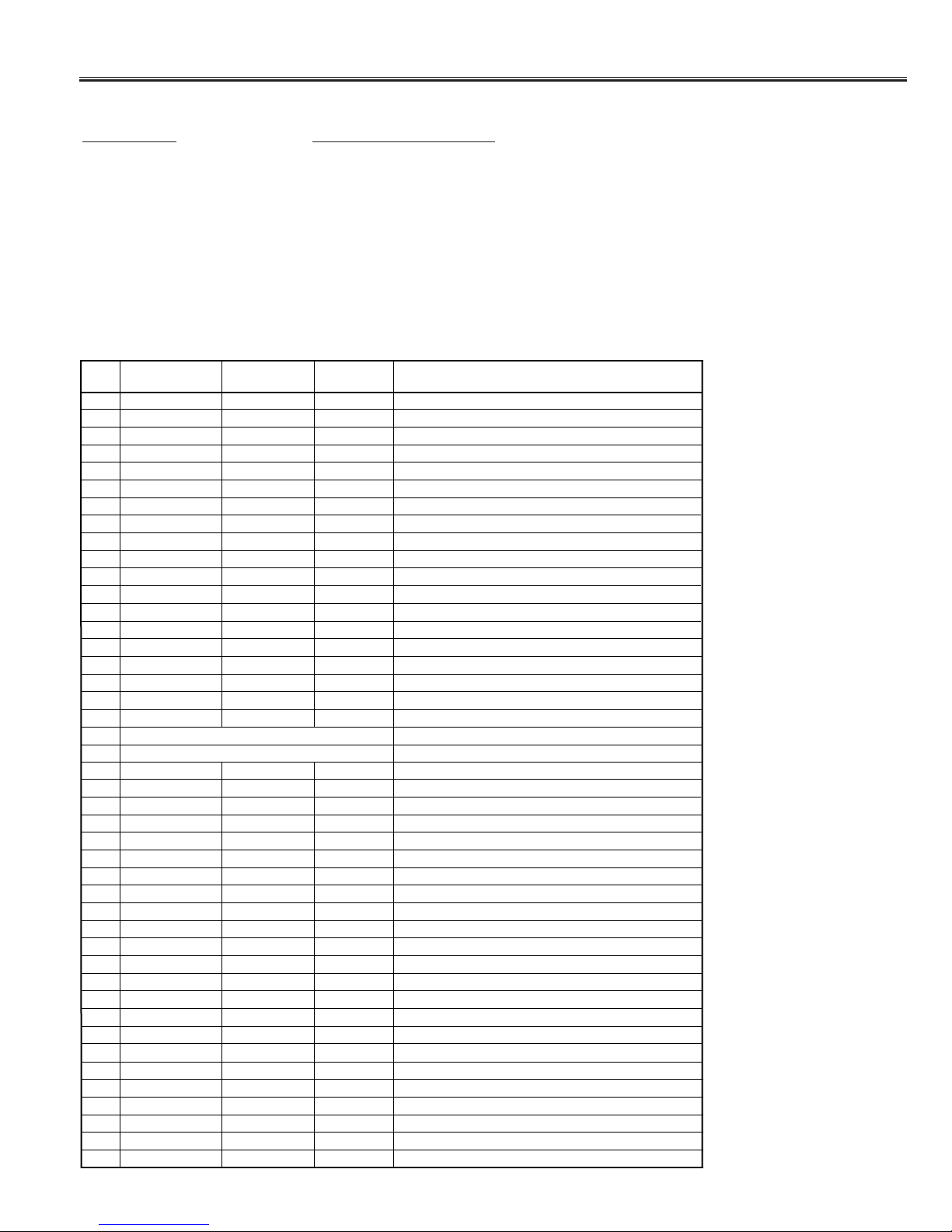
Service Adjustments with Replacing Memory IC(IC802)
NO. ITEM DATA
RANGE
INITIAL
DATA DESCRIPTION
45
46
47
48
49
50
51
52
53
54
55
56
57
58
59
Switching of RF Pre-shoot and Over shoot.
PORWN 0,1 0
RF Pre-shoot/Over shoot Adj.
PORSN 00~03 0
RF Tint Adj.
TINT -16~+15 0
NTSC 4.43 Tint Adj.
TINT 443 -16~+15 -12
RF Sharpness Adj.SHRF -32~+31 0
OSD TEXT Contrast.TEXTC -128~+127 0
Volume Control Adj.VOLUM 00~255 127
De emphasis TC.DEEM 0,1 0
VIF System Switch.VIFSW 00~03 0
SIF System Switch.SIFSW 00~03 1
Video Level Adj.V-LVL 00~07 4
FM Level Adj.FMLVL 00~31 16
IF Test.IF-TE 0,1 0
IF Test-1.IF-T1 0,1 1
IF-T2
60 IF-T3 IF Test-3
61 H-FRQ 00~63 34 Correction of Horizontal Frequency.
62 FBTS 0,1 0Switching of H-blanking and Flyback Pulse.
63 COOP 00~07 7Setting of Colour Killer Level.
64 HBLKL 00~07 7H-Blanking Control. (Left)
65 HBLKR 00~07 3 H-Blanking Control. (Right)
66 AFCRF 0,1 0RF AFC Gain & Gate Adj.
67 VSURF 0,1 0RF V-Sync. Separation Adj.
68 CDMRF 00~07 0 RF V-Countdown Circuit Adj.
69 AFCAV 0,1 1AV AFC Gain & Gate Adj.
70 VSUAV 0,1 0AV V-Sync. Separation Adj.
71 CDMAV 00~07 0 AV V-Countdown Circuit Adj.
72 HLVDRF 0,1 1
Incorrect operation prevention at the time of a special signal (RF mode)
73 HLVDAV 0,1 1
Incorrecr operation prevention at the time of a special signal (AV mode)
74 VCO-SW 0,1 0 C-VCO Adj. Switch.
75 VCO-ADJ 00~03 3C-VCO Adj.
76 CROSS-BW 00~03 0Pattern Output.
77 AVNCON 00~127 64 Contrast Adj. of the blue back in AV mode.
78 AVNBRI 00~127 64 Brightness Adj. of the blue back in AV mode.
0,1 1IF Test-2
00~255 136
79 POMT 00~255 25 Power Mute Time Adj.
80 CHMT 00~255 10 Channel Change Mute time Agj.
81 SYST 00~15 5Selection of the number of times of a Colour system judgment.
82 S-STE 0,1 1Stereo/Mono Option.
83 VOLTBL 00~03 0Selection of the change characteristic of volume.
84 CHIP818 0,1 0
Option of 818(1:TINT Control reversal)/828(2:TINT through control) selection.
300 R00 00~255 112 CPU Debug Date.
371 R71 00~255 0CPU Debug Date.
372 R72 00~255 177 CPU Debug Date.
311 R11 00~255 0CPU Debug Date.
310 R10 00~255 68 CPU Debug Date.
309 R09 00~255 112 CPU Debug Date.
308 R08 00~255 33 CPU Debug Date.
301 R01 00~255 64 CPU Debug Date.
302 R02 00~255 0CPU Debug Date.
303 R03 00~255 0CPU Debug Date.
304 R04 00~255 1CPU Debug Date.
305 R05 00~255 0CPU Debug Date.
306 R06 00~255 0CPU Debug Date.
307 R07 00~255 0CPU Debug Date.
Notes: The initial value that the CPU writes down the CPU ROM data to the memory when replaced the memory IC.
TV set may not operate correctly with this initial value. It is required to set up the fine adjustment for service
adjustments described in the above.