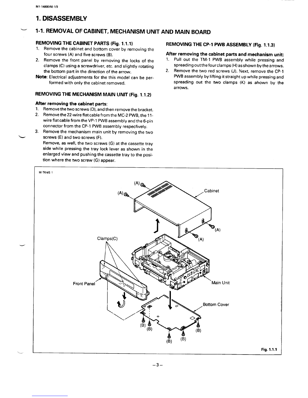
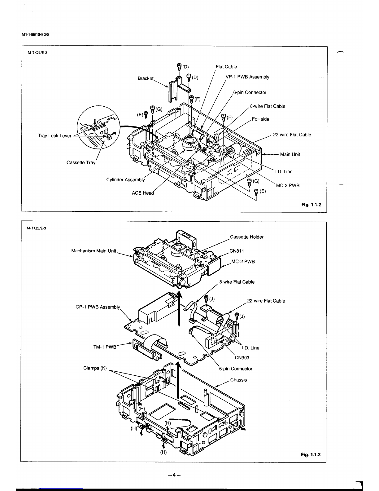
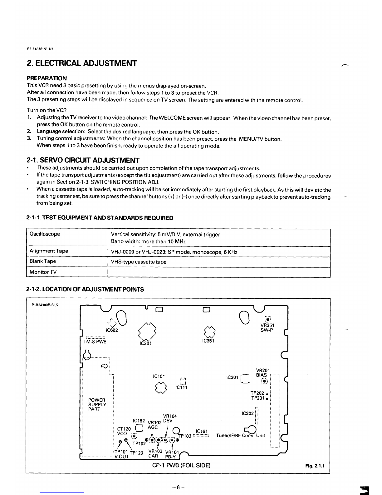
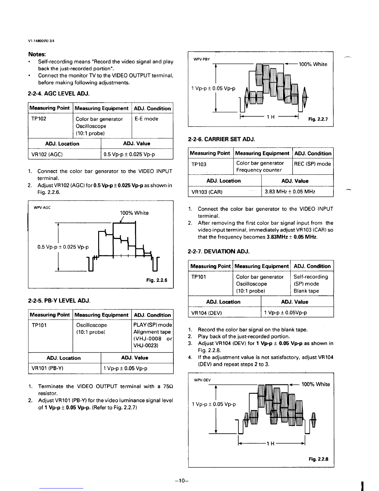
manuals.online logo
Brands
  1. Home
  2. •
  3. Brands
  4. •
  5. Sanyo
  6. •
  7. VCR System
  8. •
  9. Sanyo VHR-274G User manual

Sanyo VHR-274G User manual

This manual suits for next models

2

Other Sanyo VCR System manuals

Sanyo VCR 4500 User manual

Sanyo

Sanyo VCR 4500 User manual

Sanyo VWM-800 User manual

Sanyo

Sanyo VWM-800 User manual

Sanyo VHR-810 User manual

Sanyo

Sanyo VHR-810 User manual

Sanyo VHR-VT221A / NZ User manual

Sanyo

Sanyo VHR-VT221A / NZ User manual

Sanyo VHR-VX400 User manual

Sanyo

Sanyo VHR-VX400 User manual

Sanyo VHR-310 User manual

Sanyo

Sanyo VHR-310 User manual

Sanyo VHR-790 User manual

Sanyo

Sanyo VHR-790 User manual

Sanyo TLS-224P User manual

Sanyo

Sanyo TLS-224P User manual

Sanyo VHR-H531 User manual

Sanyo

Sanyo VHR-H531 User manual

Sanyo VHR-890 User manual

Sanyo

Sanyo VHR-890 User manual

Sanyo VHR-390 User manual

Sanyo

Sanyo VHR-390 User manual

Sanyo VHR-VK920A User manual

Sanyo

Sanyo VHR-VK920A User manual

Sanyo VWM-700 User manual

Sanyo

Sanyo VWM-700 User manual

Sanyo VHP-VX50 User manual

Sanyo

Sanyo VHP-VX50 User manual

Sanyo SRT-612DC User manual

Sanyo

Sanyo SRT-612DC User manual

Sanyo SRT-7168 User manual

Sanyo

Sanyo SRT-7168 User manual

Sanyo TLS-1960P User manual

Sanyo

Sanyo TLS-1960P User manual

Sanyo SRT-2400DC User manual

Sanyo

Sanyo SRT-2400DC User manual

Sanyo VHR-VK210P User manual

Sanyo

Sanyo VHR-VK210P User manual

Sanyo VHR-M262EV User manual

Sanyo

Sanyo VHR-M262EV User manual

Sanyo VHR-730 User manual

Sanyo

Sanyo VHR-730 User manual

Sanyo VHR-5300 User manual

Sanyo

Sanyo VHR-5300 User manual

Sanyo VHR-770 User manual

Sanyo

Sanyo VHR-770 User manual

Sanyo VHR-790 User manual

Sanyo

Sanyo VHR-790 User manual

Popular VCR System manuals by other brands

RCA VR678HF user guide

RCA

RCA VR678HF user guide

Zenith VRL4270HF Operating guide & warranty

Zenith

Zenith VRL4270HF Operating guide & warranty

Akai VS-606EA Operator's manual

Akai

Akai VS-606EA Operator's manual

Panasonic NV-SJ412EE operating instructions

Panasonic

Panasonic NV-SJ412EE operating instructions

FUNAI 27C-450 Service manual

FUNAI

FUNAI 27C-450 Service manual

Sony SLV-X37 operating instructions

Sony

Sony SLV-X37 operating instructions

JVC SR-VS20U - Dual Format S-vhs/minidv Recorder instructions

JVC

JVC SR-VS20U - Dual Format S-vhs/minidv Recorder instructions

Grundig GV 7400 EURO Service manual

Grundig

Grundig GV 7400 EURO Service manual

Zenith VCM321 Installation and operating guide

Zenith

Zenith VCM321 Installation and operating guide

JVC HR-A43U, HR-A63U instructions

JVC

JVC HR-A43U, HR-A63U instructions

Aiwa VX-S135U operating instructions

Aiwa

Aiwa VX-S135U operating instructions

RCA VR725HF user guide

RCA

RCA VR725HF user guide

JVC 0703-AH-PJ-BJ instruction manual

JVC

JVC 0703-AH-PJ-BJ instruction manual

TruTech ZV450TT8 owner's manual

TruTech

TruTech ZV450TT8 owner's manual

JVC HR-DVS1EK instructions

JVC

JVC HR-DVS1EK instructions

Sensory Science DDV2120 user guide

Sensory Science

Sensory Science DDV2120 user guide

JVC HR-VP78U instructions

JVC

JVC HR-VP78U instructions

RCA VR611HF user guide

RCA

RCA VR611HF user guide

manuals.online logo
manuals.online logoBrands
  • About & Mission
  • Contact us
  • Privacy Policy
  • Terms and Conditions

Copyright 2025 Manuals.Online. All Rights Reserved.

SERVICE MANUAL
Video Cassette Recorder
FILENO.
VHR-274G ~~etmwmy,
VHR=274EX
(GeneralEurope)
VHR-430
(NewZealand)
CONTENTS
SELF-DIAGNOSIS DISPLAY ............................2
I. DISASSEMBLY .....................................3
2. ELECTRICAL ADJUSTMENT .........................6
3. TEST POINT FOR TAPE PATH ADJUSTMENT ......... 13
4. PARTS LIST
ACCESSORIES ...................................14
PACKING MATERIALS . . . . . . . . . . . . . . . . . . . . . . . . . . . . . 14
CABINET &CHASSIS PARTS .......................14
MECHANISM PARTS .............................. 15
ELECTRICAL PARTS .............................. 18
CIRCUIT DIAGRAMS (Refer to the separate volume)
ml PAL
Please see other materials with Reference
No. given in table below.
Materials Model No. Reference No.
‘echa”
Manual tiHV%anisrn ‘s531346
~‘RODucT‘AFETY‘OT’cE
The components designated by asymbol (~)in this schematic diagram designates components whose vslue are of special significance
to product safety. Should any component designated by asymbol need to be replaced, use only the part designated in the Parts List.
Do not deviate from the resistance, wattage and voltage ratings shown.
NOTE: 1. Patisorder must contain model number, patinumber and description.
2. Substitute parts may be supplied as the service parts. :#:3@~
3. N.S. P.: Not available as service parts.
TK21G,EX,NZ 143 14S 1S,16,39 REFERENCE No. SM531367
–z–
“JaA03
aql u! uMoqe aJe sJaqunu a3uaJa4aJ [enueu asaql “Ienueu Lus!ueqaaui aql uo au-mloA a~eJedas aql OJJa4aJ‘aAoqe 60
pue 80 sJaqunu s!sou6e!p-41as aql 40 suo!]!sod Lus!ueqoaw aql ol 6U!pUOdSaJJ03 suogeJado ws!ueqoaw 40 sl!elap JO+ :eION
tH37aD
‘go sao6 JaMOd ~0] pUe ‘(Avid) ~‘(7711’3)~‘(M=J~/~~
aq] pue ‘apow lv}lINI aql ol slj!~s Anne+ s! ]oe]uoo ‘dOIS) Z‘(3YW8) 1uJoJ46u!Ao~ al!W 60
‘SUO!]eJadO dn-aye] adel ]no Sa!JJe~ LWMS uo!l!sod ws!ueqoau aql ●(7VILINI) Lsa~o~aq ws!ue~~a~ a~l
“(W1(II) So] Pue ‘(AVld) t‘(1711S)&
“uo!l!sod]uaJJnas]!le Lus!ueuoawaql .A]lne+s!l~eluoo ‘(M3W44 ‘dOIS) Z~oJ4 6u!Ao~ al!W 80
qJ!M #0 pauJn] Alq!c)JO} S! J3MOd aql q3J!Ms uop!sod uryueqoaw aql ●EDIvw Lsa~o~aq L.uswewaw aLil
“ApadoJd pa6e6
-ua IOU aAeq Ws!ueqoaw aAyp
6u!peol UJOJJ aql }0 sJea6 aql ..allasseo aq] Lo
‘uo!l!sod maJJno SJ! ]e ws!ueq~aw .ukqueqxxu Japloq auasseo 6u!poa!a uaqM paUJO~Jad aq Iouueo
aq~qJ!M}JO paUJn]AIq!3JO}S! JaMod a~l aq] u! ]q6neo s! a~asseo ade~ aql .6u!peolun IUOJ4 pue f3u!peol UJOJ~
“go sao6 JaMOd aq]
pue apow WLINI au] ol s~!ws
:suo!]eJado)aa[a aJoy3q
MO paUJn] S! ($I]!MS JaMOd al/J UaqM
“apoLu dols aql 0} s~!qs 90
:SUO!ieJadO Ea!a aJoJaq
uo pauJn] S! q31!MS JaMOd aql UauM “lq6neo s! JOOp ]UOJ} aql .
.apow 7vIllNI (“paUJJO~ad aq Ueo 6U!peOl lUOJ~)
“Anne+ .al]asseo aql 6u!poa!a uaqM
JO dols aq~ OJ s~!qs pue speoi ]uOJ+ s! ws!ueqoaw Jap[oq allasseo aql .pauJJo~ad aq ~ouue3 6u!peolun luoJ+
“A]lneJ
S! JO1OUJ6u!peol aq]JO IOJ]U03 aql .
wo!q!sod luaJJno s]! ]e urs!ueqoaw .A~ine+s! JOIOUJ6U!peOl aql .“pavasu! auasseo aq~ qI!M paUJJO#ad 50
aq] q]!M}JO pauJnlAlq!OJOJ s! JaMod a~l “lqfheos! ap!nfi ade] aql ceq louueo f3u!peolunpue 6u!peol adel
“pasealsuuaaq lou seq
a~esseoade] eq~JOaqeJqlaeJaql .
“A]1ne4s! JOSUaS pue ade] aql .
.us!ueqoaw 6u! to
-peel ade] aql u! sap!ued u6!aJo4 .(“paLUJOJJadaq uea 6U!peOlun]n=)
“#osao6 JaMOd aq] pue “ws!ueqoaw 6u!peol “pavasu! auasseo
‘apow 7vllINl aql 01 sy!qs ‘speolufl ade] aql JO SUO!peJadO aq~ u! JOJJq .aq] qi!M papeo[ aq louueo adel aql
“Allne}
s! JO1OUJuelsdeo aq]~o IOJVJO3 aql .
“apow dols aq] 01 s~!qs .A+lne+s! JOIOUJ ue]sdeo aql .&o
“a]elo~]ou saop Jo~ouJ uelsdeo aql
“paseaJ3ap Seq anbJoJ dn-a~el aq~ .
“AllneJs! IIaq aql .Zo
“apowdols aql o] s14!qS “lq6neos! laaJdn-a~e~ aql .“aleloJ Iou saop laaJ dn-a~el aql
“JapU!lAO aql punoJe spu!MadeJaql .
.AllneJ
s! JO]OUJ JapU!lA3 aq140 IOJJUOOaql .10
“apoLu dols aq! 01 s~!qs A~lne+s!JO1OLUJapu!IAoaql .“aJe]OJJOUSaOpJO]OLUJ9pU!IA3aql
WU9JJK)30 J~~V W?lS
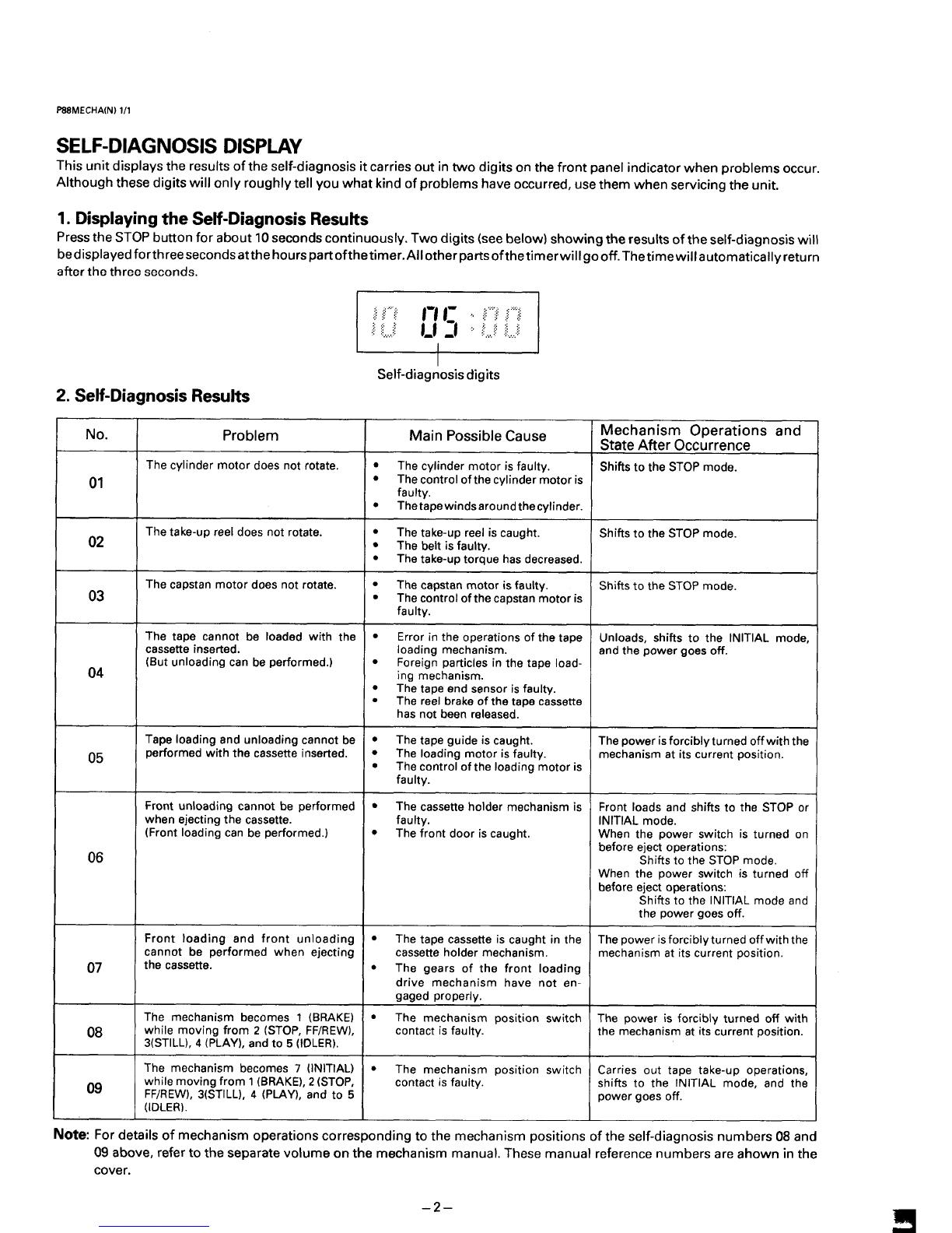
pue suol]eJadO ws!ueqcmw asne~ alqfssod uje~ LLJf31qOJd “ON
s~psqj s!soufha-jlas “z
sl!lip s!sou6e!p-+laS
II
II
“spuo3as aaJql aq~Jage
uJnlaJAlle3!lewoln ell!Maw!laql "~oo611!mJaw!]aq] josved JaqaollV.Jaw!laq340 vedsJnoqaqaie spuo3asaaJqlJo4 paAelds!paq
II!M s!sou6e!p-}las aql JOs]lnsaJ aql 6u!Moqs (Molaq aas) sJ!6!p oMl ‘Alsnonuquoa spucmas 0Llnoqe JOJuounq dols aql ssaJd
sqnsa~s!sou6e!a-#aSaq~6u!Aelds!a“L
“qun aql 6U!3!AJaSuaqM Luaql asn ‘paJJfWOO aAeq SUJalqOJd40 pu!y IeqM noA Ilal Aiq6noJ AIUOII!M s1!6!P asaql q6noqllv
“Jnxlo su.JalqoJd uaqm JoJewpu! Iaued 1UOJ4aql uo s1!6!p ON u! Jno sa!JJe3J!s!sou6e!p-41as aq~40 sllnsaJ aql sAelds!p l!un s!ql
AWldSKl SISONWK1-d13S
W(N)VH33WeSd
M1-14801xN)1/3
1. DISASSEMBLY
-1-1.REMOVALOFCABINET,MECHANISMUNITANDMAIN BOARD
REMOVING THE CABINET PARTS (Fig. 1.1.1) REMOVING THE CP-I PWB ASSEMBLY (Fig. 1.1.3)
1. Remove the cabinet and bottom cover by removing the
four screws (A) and five screws (B). After removing the cabinet parts and mechanism unit:
2. Remove the front panel by removing the locks of the 1. Pull out the TM-1 PWB assembly while pressing and
clamps (C) using ascrewdriver, etc. and slightly rotating spreading outthefourclamps (H) as shown by the arrows.
the bottom part in the direction of the arrow. 2. Remove the two red screws (J). Next, remove the CP-I
Note: Electrical adjustments for the this model can be per- PWB assembly by lifting it straight up while pressing and
formed with only the cabinet removed. spreading out the two clamps (K) as ahown by the
arrows,
REMOVING THE MECHANISM MAIN UNIT (Fig. 1.1.2)
After removing the cabinet parts:
1. Remove the two screws (D), and then remove the bracket.
2. Remove the 22-wire flat cable from the MC-2 PWB, the 11-
wire flat cable from the VP-1 PWB assembly and the 6-pin
connector from the CP-I PWB assembly respectively.
3. Remove the mechanism main unit by removing the two
screws (E) and two screws (F). “
Remove, as well, the two screws (G) at the cassette tray
side while pressing the tray lock lever as shown in the
enlarged view and pushing the cassette tray to the posi-
tion where the two screw (G) appear.
M-TK4/E-l
Front Panel
Fig.1.1.1
–3–
‘b–
w
&“L”L‘6!j
sduml~
P/l
flMd l-do
alqE~ p?pJ
wLIJs!ueqsaw
cmuu-w
~L”L “fi!j
Ey)
alq~ JaAa7 ~007 AI?J1
Z-YIZY1- w
122(NJLOIWL-LLAJ
M1-14S18(N)3/’3
TEMPORARILY SElllNG UP AND CONNECTING MAIN PWB ASSEMBLY
The following is an example of how to place and connect the main PWB not requiring ajig, when repairing the
CP-1 PWB assembly (Fig. 1.1.4)
1. Place the mechanism-main unit at the fixed position on 3. Place the CP-I PWB assembly above the mechanism
the chassis. main unit along the cassette holder. Insert the tip (L) of
2. Connect the 29-wire flat cable to the MC-2 PWB ,and the the terminal board into the opening (M) at the side of the
8-wire flat cable to the VP-1 PWB assembly, Connect the chassis, as shown in the enlarge view.
TM-1 PWB assembly to operate VCR by using the remote
control.
“L
8-wire Flat Cable
VP-1 PWB Assembly=
6
w
chassis-KiiEiE
i
./ /
M-TK2LE-4
cP-
Tip (L)
Mechanism Main Unit’
I
‘~/Q&’J\~\Mc2pwB ..s.t?W?..,Wr
ACE Head 6-pinConnector
Opening(M)
Fig. 1.1.4
1-2.MAINCIRCUITBOARD
L-TEl/G
Shield Case
(Power supply Part)
●TM-8 PWB
(For VHR -274G)
Y
//=f ‘P-’PWBASSY
::::%%%;)l/ ...*E
●TM-7 or TM-8 %$%Y\ rMC-2 PWB
(On the Mechanism Unit)
Tuner/lF/RF conv. Unit
TM-1 PWB --CP-I PWB Fig. 1.2.1
–5–
–9–
L“L”Z “6!~
L
(3WS 7104) WI&4 l-do
lno”A ;“-”--””””””-”””-””-”””-:
A3az0LuA 29121 ;
IUWA
1!:: :.:
::
1--
I●ZOZdl
i(“j
i-...-.: Svla c1 10Z3
10ZHA
L,~.~,31 c)
:..-..:LOL31
r!EQ_L ‘1
Q
.................
nSMd 8-lAJl
,-------------
...............
Z/LS-SOO&?ZEld
SINIOd lN31NlSflNlV dO NOUV307 Z-l-Z
,11
AIJOJ!UO~
adel a~asse3 adA]-SHA adel qUQ[s
ZH~ 9‘adoosouow ‘epOUJds :ccO@rHA JO (30(jo-f7+A adelluawu6!lV
ZH~ 01 ueqlaJow :qlp!M pues
Ja66!JJ leuJalxa ‘Al~AUI cj :A][A!1!SU9S Ie3!]JaA adoasolposo
a3Uln03u saknfaNvls aNv lN3uudin03 Lsm. L-L-2
.las 6u!aq UJOJ4
—6u!y3eJ1-olnewaAaJd o~qoeqAeld 6U!MeE Jaye Ap3aJ!p aouo (–) JO(+) suol.lnq Iauueqoaql ssaJd ol aJns aq ‘JasJalua3 6U!~3eJl
aqlale!Aap Il!M s!ql sv .qoeqAeld lsJ!j aql 6u!Uels Jal.JeAlale!paww! las aq II!M 6UppeJJ-Olne ‘papeols! adel al.lasseo euaqM .
“rav Noulsod 9NIH3JJMS .2-L-z UWWS w u!ebe
Samtpaoojd aql MOIIOJ‘Sluawlsn!pe asaql Jal.Jelno pa!jjeo aje (luawlsn!pe lI!l ayl Jdaoxa) Swauwmlpe UOdSUeO adel aql jI .
“Swawlsn[pe VodsueJl ade~ aqljo uo!la{duoo uodn Ino pap.!e~ aq plnoqs .sJuawlsn[pe asaql .
mwsnraw maw 0AL13S.L-z
.apouJ 6u!leJado Ile aql aleJadO 01 ApeaJ ‘qs!u!4 Uaaq aAeq g01 Lsdals uaqM
“Uollnq ~flN~LAJ aql ssaJd ‘lasaJd uaaq Seq uo!ysod Iauueqo aql uaqM :sluaw!sn~pe loJwoa 6u!unl .S
“uolJnq >0 aql ssaJd Uaql ‘a6en6uel paJ!sap aql Ioalas :uoqoalas a6en6uel .Z
qoJwo2 alowaJ aql uo uounq YO aql ssaJd
‘lasaJd uaaq Seq Iauueqo oap!Aaq~ uaqM ‘Jeadde \l!M uaaJ% q~O~7qAAaql :Iauueqo oap!A aql oJJaA!aaaJ~aq~6u!3sn[pV “1
USA aql UOUJnl
“loJluocIa]owaJ aq~ qym paJav_iaaJe 6u!uas aql uaaJos Al uo aouanbas u! paAelds!p aq II!M sdals 6u!llasaJd gaql
‘WA aql lasaJd ol &o] 1sdaw Mollo} uaql ‘aPeLU uaaq aAeq uoqoauuoo Ile JaqV
“uaaJX-uo paAelds!p snuaI_u aql fiu!sn Aq 6u!~asaJd o!seq &paau ~~A s!ql
NOUVUVd31dd
mmusnraw7VWU23T37
Z/l (N)81LW1-lS
SI-14801(N) 2/2
P1B08800C-S1
1— Shield case
,,,,”rrent1// \
TP181
TP183 SW-P +~~~,8~
TP182 ENV -
REC-YIC
IVP-1 PVVB Assembly Fig. 2.1.2
Note:
.Self-recording means ‘Record any broadcasting or video
signal and play back the just-recorded portion”.
2-1-3. SWITCHING POSITION ADJ.
Measuring Point Measuring Equipment ADJ. Condition
TPIOI Oscilloscope PIAY mode
(VIDEO OUT) Alignment tape
TP183 (SW-P) (VHJ-0009 or
VHJ-0023)
ADJ. Location ADJ. Value
VR351 (SW-P) 6.5 H10.5 H
1. Set the tracking control position to the center by pressing
CHANNEL buttons (+) and (-) simultaneously.
(Tracking center position display in the indicator
panel “T -:- “)
2. Adjust VR351 (SW-P) so that the width ‘T” becomes 6.5 H
A().5 Has shown in Fig. 2.1.3.
WS-SWP
T= 6.5 H*0.5 H
IFront edge of ~
Ivertical sync signal
tt
Rise RF. SW. PULSE
Fig. 2.1.3
2-1-4. STILL V-LOCK ADJ.
Measuring Point Measuring Equipment
Picture of Color bar generator
monitor TV or
Broadcasting
Monitor
/7
ADJ. Condition
Self-recording
(SP mode)
STILL mode
Blank tape
ADJ. Location ADJ. Value
CHANNEL (+) button The minimum vertical shake
CHANNEL (-) button
1. Play back the just-recorded portion and then set the VCR
in the STILL mode.
2. Press the CHANNEL (+) button or the CHANNEL (-) button
so that any vertical shake of the picture is brought to its
minimum.
–7–
‘8–
w“ -.
“+ —
+--aay9eJg
AlqwassV o
9Md l-dfi YIZ>l-AdM
.-
“pau!elqo
aq ueo a6ew! yaeq Aetd JadOJd ou Pue punoJ6 lua!~!~nsu!
s! aJaql ‘Joewoo 10U saop Alqwasse gMd l-dA aql 413oa44a
pla!qs aql u!ew!ew 01 Alqwasse QMd l-dA aq~ @la?seJq
LWM aseo plaw 40 pua Ue Joeluoo a%ew 03 aJns aq ‘Alqwasse
8Md l-dA aql 6u!wn!pe lJaqM ‘JaqVn3 “&”z”z%!j u! UMOqS
Se ‘Alqwasse gMd L-dA aql }0 lUaUJISnlpe pUe 6U!J!edaJ
aldtu!s ap!AOJd 01 6!1 AelaJ aql 6U!sn Aiqwasse EIMd l-dA
aql ol Alqwasse Japu!lAo aql UJOJ}pua alqeo Iei} aql loauuoa
wAvm uwusnrav ‘z-z-z
L“Z”Z.6!4
(8000-rHA) WLI043AVM 7VN!31S klV8 H0700
Ieu61s WAS-H
7VN!IIS W= UO1OO 3dVl lN3WNEN7V
AlqwassV sMd l-dA Jo} alqe~ lel} aJ!m-S :q900-rHA 6!T AelaH Juawlsnrpv
s1!6!p weo!}!u6!s 8Jaluno~ AOuanbaJ-J
(l:l)zHIAJ O&-X
(1:01) zHkll OP-SO :AmJanbaJ}6U!JaAOS
(L:L)@ o? Uew Sw
(L:OL)W ~z Uwl sw :W@de~ Jndu[ aqOJd adossoll!mo
adel a~asseo ad&SHA adel quela
(l”z”Z “6!4 ol JaFW “AAolaqPaq!J~saP s! uJJo~aAemleu6!s Jeq Jolo3)
zl+qL ‘Jeq JOI03 ‘aPOUJ ds :&zCl@rHA JO 80()@rHA Iadel waumfi!lv I
a6ueJ ~a JalawqoA Iel!fi!o
ZHM 01 Ueql aJOUJ:qJp!M pUe8
Ja66!Jl leuJalxa ‘Alo/AUJ q:Al!A!l!suas leo!uaA adoosoll!oso
(lau6!s Jeq JOI03 f)H3) laAal al!qAA%001 ql!M lau6!s Jeq Jolo3 lVd JoleJaua~ leu6!S Jes JOIOO
I
a3wnow sawaNvls aNv mwdm33 1s31 ‘L-2-Z
“Alqwasse sMd L-dA aql 40 wau-osn!pe aldw!s aP!AoJd OJ6!! AelaJ aql aw
“waduo~ wPww lN9kvlsnrav llnotils OAuas “1-z uo!13aS ‘sluawlsn!pe 6U!MOIIOJ aql 6u!qew aJoJag .
W(N)lOEV1-L
VI-14818(N)2/4
2-2-3. LOCATION OF ADJUSTMENT POINTS
P1BOB800C.V1
Shield Case
o
‘Yi’ “
@
-- 0
..—
TP181
REC current
TP183 SW-P
.- VR 182 REC-Y/C
,.>; TP182 ENV
VP-1 PVVEIAssembly Fig. 2.2.4
PlB243@3B-Vl/2
+
T
uo0●
,.. T,....,
~::’... :e:
,,’
1c)
...,,
..,.
0
VR351
IC602 SW-P
...............
...............
TM-8 PWB IC351
IC301
o... ..............
a;
!... VR201
IC201c1
BIAS f------j
,....
:e:; ~
,....,;
,0
POWER ;
~SUPPLY ~...
:,
;PART ;!:
VR104
1C162 VR102 ‘Ev
CT120 O’p /0
Vco [j-: IC161
............, Q
.... ..,t-.-::r..:r...:Tpl 03 .............
TP1 02°[9.::.9,:*..?c:’.:.: O
v<
Unit
ft .........
;TP101 TP120 V~~~3 VR101
:.......................! V.OUT PB-Y
CP-I PWB (FOIL SIDE) Fig.2.2.5
Iclol :-.-,-:
0
::
:...!
Iclll
–9–
–ol–
“&01 zsda~s leadaJ pue (Ad(l)
VOLHA Isn!pe‘~mwes 10U S!~weA wawn!pe =w 41 w
“8”Z”Z“6!4
u! uMoqs se d-dA qtyo Td-dA I, JO+(AqCI) VOI,HA lsnlpv “&
.uo!~od p~pJOXJJ-lSnl aql JOyoeq Aeld “Z
“adel quelq alp Uo leu6!s Jeq JOIOOaql pJOOa~ “L
d-dAS()”()Td-dA L(AXI) POIEIA
IanleA “fav IUo!Jmol “fav I
ade] quels (aqOJd l:oL)
apow (dS) adoosoll!oso
6u!pJo3aJ-Jlas JoleJaua6 Jeq JoIo~ 10ldl
UO!l!pUO~ ‘f’av wawd!nbq 6u!JnseaW w!od 6u!JnseaW
‘raw NOIIVIAWI “L-z-z
“zHw SO-OTzHM~”& sawooaq Aa.JanbaJ4aql Jeql
os (HVS) &OLHAISnlpe Alale!pawu! ‘leU!I.UJallndU! oap!A
al$ LUOJJ mdu! leU6!S Jeq JOI02 JSJ!Jaql 6U!AOUJaJJaljV “Z
.leu!wJal
llldNl 03alA w 01 JQeJaua6 JW Jolo~ aql l~auuoo “1
Z“w ~()”() TZHW &g”& (HV3) &OlklA
anleA .fav Uo!}mol “~v
Jalunoo AcmanbaJ3
apow (dS) ~q~ Jo]eJaua6 Jeq JOIOS &Oldl
UO!J!XJO~ “Mv Iuawd!nbq fiu!mseam ~u!odfiupnseam
‘raw L3s WWV3 ‘9-z-z
‘“22“6!’ +“L---4
Afld-AdM
(L’Z”Z“6!4 o~Ja4akl)“d-dAS0”07 d-dA 1Jo
laAal leu6!s aoueu!wnl oap!A aq]Jo} (A-gal) 10l~Awn[pV “Z
“JOIS@J
wi~ eww iwuJa mdlrm 03alA aw aleu!wjal “L
d-dA S0”0 Td-dA LI(A-ad) 101HA I
(&ZOO-rHA
JO 8000-rHA)
adel wawu6!lV
CIpOUJ(ds)Avld
uo!~!puo~“mv
(aqoJd I.:OL)
adoosoll!oso 10ldl
wawd!nbq 6u!.msea~ ~u!od6u!msea~
V’(JV 13A37 A-Od “!72-2
9-Z-Z ‘W
‘3”0
“9.z”z“6!4
“leu!wJal
lndNl 03alA W 01 JQeJaua6 Jeq JOIO~ aW l~~uuW3 “1
d-dA ~zo”o Td-dA Cj”I) (SW) ZOlklA
anleA *Mv UO!}~Ol “MV
rapow 3-3
1
(aqOJd L:ol)
ado%oll!oso
JOleJaUa6 Jeq JOIO~ ZOldl
wautd!nbq 6u!.mseaW ~U!Od6upnseaW
‘raw 13A373WI “9-Z-Z
“sluauJlsnlpe 6U!MOII04 6u!~ew aJojaq
‘leu!wJal Lfldlflo Oq(llA aql 01 ~Jol!uouI aql loauuo~ .
“.uo!vod papJooaJ-wn[ aql qoeq
Aeld pue leu6!s oap!A aql pJooa~Msueaw 6U!pJOOaJ-jlaS .
:S~~ON
*/&(N)O~l-lA