Sanyo VHR-290 Series User manual

L
Service Manual Video Cassette
Recorder VHR-290 series
VHR-291 series
VHR-294 series
VHR-28 series
VHR-29 series
-d+
TABLE OF CONTENTS
1. CIRCUIT BOARD LOCATIONS
1-1. MAINBOARDS ..................................................................... 1
1-2. LOCATION FOR TAPE PATH ADJUSTMENT ................................... 1
2. ELECTRICAL ADJUSTMENT
2-1. Preparation ..................................................................... 2
2-2. SERVO CIRCUIT ADJUSTMENT ................................................. 3
2-3. VIDEOCIRCUIT ADJUSTMENT .................................................. 5
2-4. AUDIOCIRCUIT ADJUSTMENT .................................................. 7
2-5. LEVEL METER CIRCUIT ADJUSTMENT ......................................... 9
2-6. MTSDECODER CIRCUIT ADJUSTMENT ...................................... 10
2-7. VIDEOTEH DECODER CIRCUIT ADJUSTMENT ............................. 11
2-8. TUNER lFCIRCUIT ADJUSTMENT ............................................. 12
3. DISASSEMBLY PROCEDURES
3-1. REMOVAL OF REMOTE CONTROL UNITCASE ............................. 13
L
FP4H, FP4HV series REFERENCE No. WM-531054
-.—

3513 L11(N)
1. CIRCUIT BOARD LOCATIONS
1-1. MAIN BOARDS
TM-
L13L072
Video pre-amp unit= _~CP-1 (Video,Servo& Audio)board
rvv -I\ruwcu WWIYI waIu/2714
m.! ,in-...-. ,.. .. . ..l..iL-.-...4
-.
(Display,Timer & Tuning control)boardmtiq:;;;:::r”
LTN-5 (NICAM decoder) board
Installed specific equipment and models
TN-3 (MTS decoder) VHR-2901, 280ES, 294G, 281,291 and 290 (Australia).
TN-5 (NICAM decoder): VHR-2901R, 290ES, 291 E, 29SP and 280 (New Zealand).
TM-6 (Videotext decoder): VHR-294G and 29SP,
TM-8 (VPS circuit)board: VHR-284G.
Appearance and specifications are subject to change without notice.
Fig. 1-1
1-2. LOCATION FOR TAPE PATH ADJUSTMENT
NOTE: Test point TP182 and TP183 for tapa path adjustment is shown in figure below.
For adjustment, refer to the separate volume “Mechanism Sewice Technical Information”.
FC6L019
Shield case TP181 VR181 VR182
~l>n.RE~~ ~u.<rF~
a
TP291 TP183 TP182
AF REC SW PULSE ENVELOPE
Fig. 1-2 Pre-amp unit
‘d”
—l—

3513J11(N)
2. ELECTRICAL ADJUSTMENT
L2-1. PREPARATION
2-1-1. EQUIPMENT
●
●
●
●
●
●
●
●
●
●
●
●
✍●
●
●
●
Colour TV monitor
PAL Colour-bar generator (with RF and LINE OUTPUT)
PAL TV test signal generator (Multi-burst signal with
colour burst)
Audio signal generator
Oscilloscope (dual trace; frequency response: 10MHZ or
more; probe: 10:1 )
Frequency counter (countable to 10MHZ or higher)
Digital voltmeter
AC voltmeter
In/output probes
Alignment cassette (VHJ-0008) PAL Colour bar 1KHz
Alignment cassette (VHJ-0009) Monoscope 6KHz
Alignment cassette (VHJ-0023) PAL Monoscope 6KHz,
PAL Colour-bar 1KHz, SECAM Colour-bar 1KHz, PAL RF
Sweep MESECAM Colour-bar 1KHz, NTSC Colour-bar
1KHz.
Alignment cassette (VHJ-0080) PAL colour bar HiFi BPF
Alignment cassetee (VHJ-0020) AF level colour bar 1KHz
Relay jig (VHJ-0067) 12-wire cable for Pre-amp unit
Connect the Flat cable end from the Drum assembly to the
Pre-amp unit using the Relay jig to provide simple repair-
ing and adjustment of the Pre-amp unit, as shown in Fig,
2-1-1. Further, when adjusting the Pre-amp unit, be sure
to make contact an end of Shield case with Bracket of the
Pre-amo unit to maintain the shield effect.
Relay jig (VHJ-0088) 22-wires cable for AD-2 board
Connect the Flat cable end to CN251 of the CP-1 board
and other end to CN271 of the AD-2 board using the Relay
jig (Shown in Fig. 2-1 -2) to provide simple repairing and
adjustment of the AD-2 board.
%
Relay jig <~“ {
‘\
Flat cable
Slinder &,
assembly /
PlaJo35
@-a
I1~
W‘Erracket
Fig. 2-1-1
RMJol 4
IFig. 2-1-2
L2-1-2. SET-UP
Because the RF input signal is used for circuit adjustments, oCheck to be sure that there is no spike noise in the sync
connect the colour-bar generator to the ANT IN terminal of
the VCR. The RF input signal is processed by the tuner and
IF circuit. It is important that the video output signal of the IF
circuit satisfies the items shown in Fig. 2-1-3. Connect the
oscilloscope to the VIDEO OUTPUT terminal of the video
circuit and terminate with a75Q load, and then check the
video output signal.
sThe amplitude of the sync signal should be approxi-
mately 0.3 VP-P,
“The amplitude of the video signal should be approxi-
mately 0.7 Vp-p.
“While observing the oscilloscope or TV screen, make
fine-tuning adjustments so that the colour burst
amplitude is approximately 0.3 Vp-p.
part of the horizontal sync signal
100%
P
o.
-P
Hsync si&al
Fig. 2-1-3
—2—

3513S11(N)
2-2. SERVO CIRCUIT ADJUSTMENT
QThese adjustments should be carried out upon completion of the tape transport adjustments.
.If the tape transport adjustments (except the tilt adjustment) are carried out after these adjustments, follow the procedures -
again in Item 1SWITCHING POSITION ADJ.
.When acassette tape is loaded, auto-tracking will be set immediately after starting the first playback. As this will deviate the
tracking center set, be sure to press tracking buttons (+)or (–) once directly after starting playback to prevent auto-tracking from
being set. Press the tracking buttons (+) and (-) simultaneously, the tracking control to the center position.
oUnless otherwise specified, all test point and adjustment location on the CP-1 board.
10.
1
—
2
A
Item
SWITCHING
POSITION
SP SLOW
TRACKING
Input
Alignment
cassette
(VHJ-0009
VHJ%23)
Colour bar
from
Colour bar
generator
Mode
PLAY
SP mode
REC
I
PLAY
i
STILL
1
SLOW
Point
VIDEO
OUTPUT
TPIOI
RF SW
pulse
TP183
(Video pre-
amp unit)
TV screen
Location
VR351
TRACKING
buttons
and
REC button
Front panel]
Remark
W25SC01
~65Hfi
RF switching
pulse
Vtdeo signal
7654321 —
Vsync
1Press the tracking buttons (+) and (-) simul-
taneously to the tracking center position (in-
dicator panel displayed: “T —:— “).
2. Adjust VR351 so that the phase of the lead-
ing edge of the vertical sync signal is delayed
6.5 t0.5 Hfrom the rise of the RF switching
pulse waveform.
W20S011
Noise at —
upper side
m‘:”
1.
2.
3.
4.
5.
6.
w~~~de
Set the VCR in the SP REC mode and record
at the middle of the cassette tape.
Playback the recorded part, and set the SP
STILL mode.
Press the tracking buttons (+) or (-) until V
jitter (very fine movement of the vertical
sync.) is minimized.
Set the SP SLOW mode by remote control unit.
Press the tracking buttons (+) and (-) simul-
taneously to adjust the tracking to the center
position (displayed: “T —:— “).
Press the REC button during the tracking
center display (approx. within three sec-
onds), at this time make sure that display as
shown ‘T— :—“.
Press tracking buttons (+)or(-) to send away
the noise which appears on the monitor
from the screen, and also adjust the position
of the noise at the upper side of the screen to
the similar position of the one at the lower
side judging from the center of the screen.
Press the REC button during the tracking
center display (approx. within three sec-
onds), at this time make sure that display as
shown “T— :—“.
-----
–3–

3513S21(N)
io. Item Input Mode Point Location Remark
W20S011
Noise at —
E
. . ..-. .........
------- --------- Monitor
------- --------
upper side screen
Noise at
----- ------ ----
----- ----- ..---- Iower side
----- ------ ..-.
1. Set the VCR in the LP REC mode and record at
the middle of the cassette tape.
2. Playback the recorded part, and set the LP
STILL mode.
3. Press the tracking buttons(+) or (-) until Vjitter
(very fine movement of the vertical sync.) is
LP mode minimized.
REC 4. Set the LPSLOW mode by remote control unit.
Colour bar JTRACKING 5. Press the tracking buttons (+) and (-) simul-
LP SLOW from PIAY buttons taneously to adjust the tracking to the center
3TRACKING Colour bar TV screen and position (displayed: ‘T —:— “).
generator ST:LL REC button Press the REC button during the trakcing
(Front panel) center display (approx. within three seconds),
SLiW at this time make sure that display as shown
“T- :–“.
6. Press tracking buttons (+) or (-) to send away
the noise which appears on the monitor from
the screen, and also adjust the position of the
noise at the upper side of the screen to the
similar position of the one at the lower side
judging from the center of the screen.
Press the REC button during the tracking
center display (approx. within three seconds),
at this time make sure that display as shown
“T– :–“.
Note: Skew may occur at the upper side of the
playback monitor screen during the LP
mode, do not mistook this for noise.
PI 2s050
TB-1 board ~-._-_.----_.--------T
L------------- = = z=-_: ---- =c==------- =-------- :::-_-_-_-o-_@—---:-_-_T
TB-2 board TP101 VIDEO OUT RF converter ~
1
cz=--------------------------------- ~,
________________ _______________
,--- L_-- _-- __-- _-__-----,
---------- —-—- —----- .
{~j VR201 VR 102 11
IC201 BIAS AGC ,-- tVIF unit ,
e---------- ~--.,l::e,e, VRICM
l------.-~ TP103:L!?.’+-J DEV L-------- _--_ ---_ --__-,
.-------—---------—--
1
TP202 ● ● TP201 I
[-----------1 VR103 1Tuner
(COLD) (HOT) Q1012 ;Iclol <CAR L-–_ --___________J_J
7) i---------- +.~ ~------~ c=-----_,__------,
______________
[-:::::-] ~::-:::] : ---- IIC162 ‘>
TP102 $1,~-j L-----_, TN.3 ()- VR631
lC26~ 1
IC261 VR101 PB-Y board SEPARATION
~===___ ---__3
--------
0‘iii; 00
TN-7 board
~------_-l
----------
IC234 IC603
IC233 ~~==:::
:: C:----- __,
------
{~ c1 00 TM-8 board
j~VR236 VR351 ;---:
I I R-PB vR239 SW-P ,%
+.
:,ej
o
BPF >--+-1 ‘R235 ~--___------_l
,-~,,e 1..., L-PB t,
[e: IC231 (e); -’ ;, IC351 1
,
VR243 .-. ●
:.9,:TP243 VR233 ----------- J
NR
1
VR243 TP:33 L“Fo
R-FO TP:34
r-:
:;
; ! CN251 o
IC301
II
:* IC304
LJ,.--7
L--’;
*
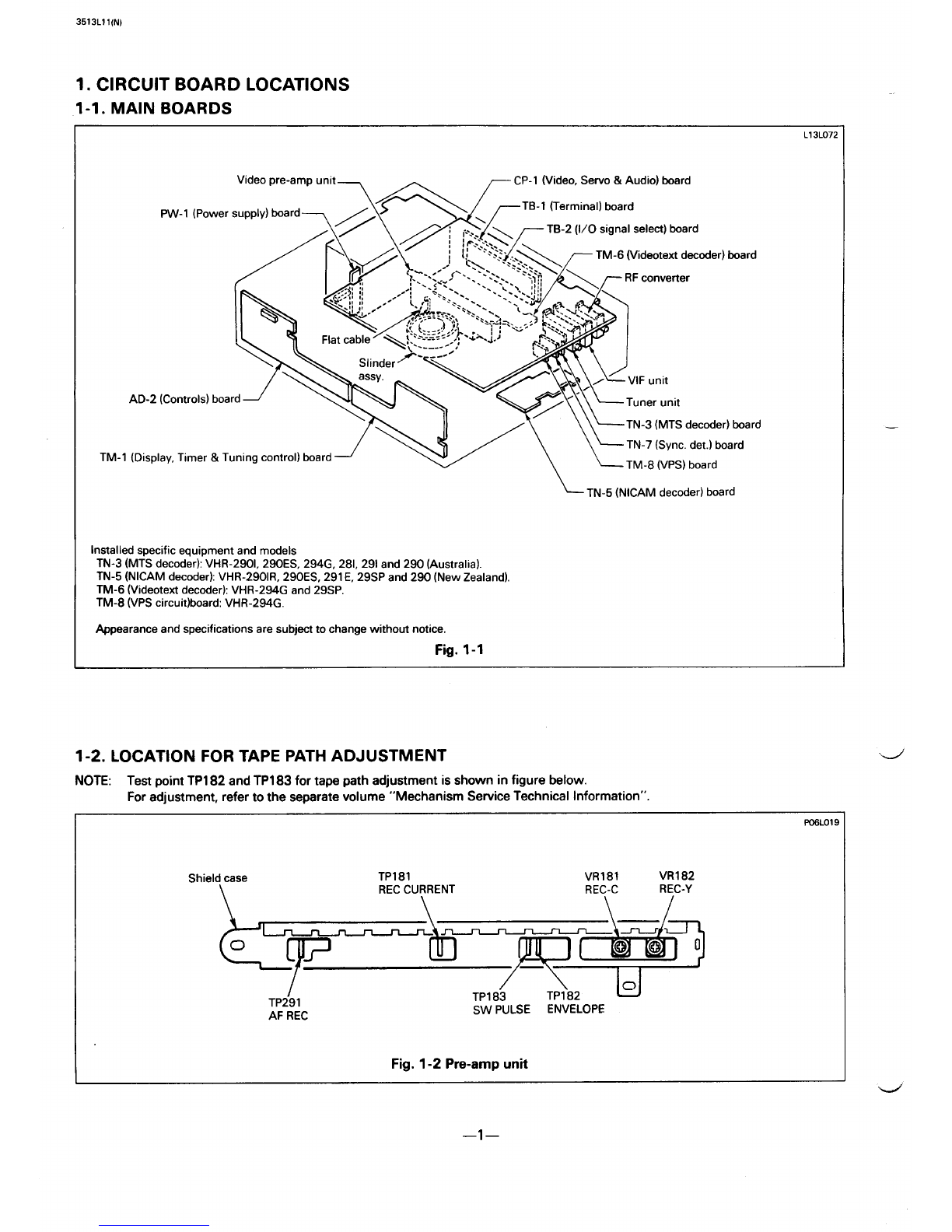
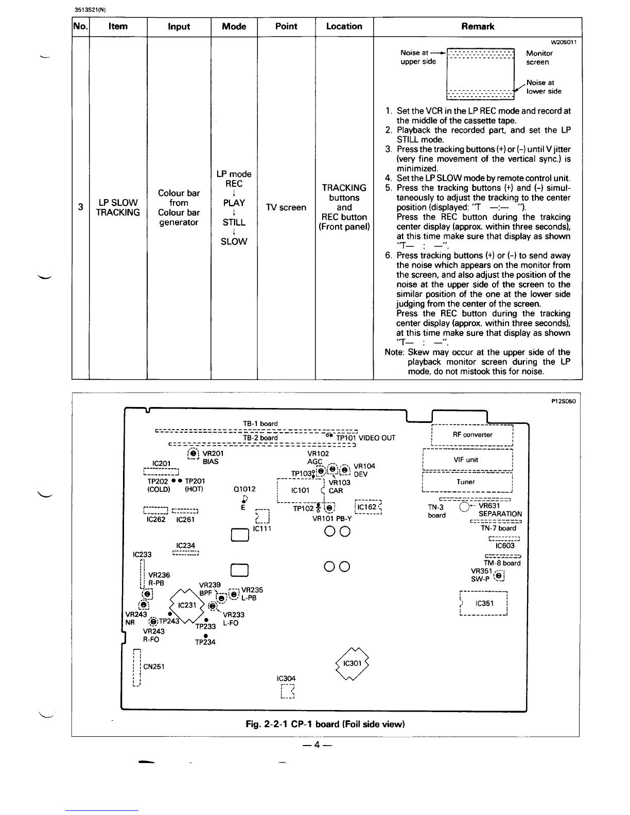
Fig. 2-2-1 CP-1 board (Foil side view)
—4—
——

3513V11(N)
2-3. VIDEO CIRCUIT ADJUSTMENT
“Use the Relay jig mentioned in the 2-1. PREPARATION to provide simple adjustment of the Video Pre-amp unit.
oBefore these adjustments place the unit in the SP mode.
“Unless otherwise specified, all test point and adjustment location on the CP-1 board.
—
10
—
1
—
2
.
3
—
4
—
Item
AGC
LEVEL
PB-Y
LEVEL
CARRIER
SET
DEVIATION
Input
Colour bar
(100% white
level)
from
Colour bar
generator
Alignment
cassette
(VHJ-0008
VHJ&23)
Colour bar
(100% white
level) from
Colour bar
generator
1
No-signal
Colour bar”
(100% white
level)
from
Colour bar
generator
Mode
E-E
PLAY
REC
REC
(Adjust-
ment)
1
PLAY
(Check)
Point
TP102
VIDEO
OUTPUT
TP101
TP103
VIDEO
OUTPUT
TP101
Location
VR102
VR101
VR103
VR104
Remark
W25V03C
T100% white
L@4E?:
1. Terminate VIDEO OUTPUT terminal with a
75 ohms.
2. Adjust VR102 so that the level is 0.50*
0.025 VP-P.
W25VO01
-1 tXIO~ white
* 0.05 Vp-p
1. Terminate VIDEO OUTPUT terminal with a
75 ohms.
2. Adjust VR101 so that the level is 1.00 *
0.05 Vp-p.
1.
2.
3.
Input the PAL colour bar signal to VIDEO
INPUT terminal.
Set the channel selector buttons to the “AV”
position and put the VCR in the REC mode.
After removing the first colour bar signal
input from the video input terminal, imme-
diately adjust VR103 so that the frequency
becomes 3.83 *0.05 MHz.
W25W@
-1OOYO white
* 0.05 Vp-p
1. Terminate VIDEO OUTPUT terminal with a
75 ohms.
2. Insert the blank tape to the VCR and record
colour bar signal.
3. Playback the recorded part, and check that
the level is 1.00* 0.05 Vp-p.
4. If the adjustment value is not satisfactory,
adjust VR104 and repeat step 3.
-
—5—

3513V21(N)
—
b
—
5
—
6
—
Item
CREC
CURREN
YREC
CURRENT
Input
Colour bar
from
Colour bar
generator
Colour bar
from
Colour bar
generator
Mode
REC
REC
Point
TP181 (HOT)
Shield case
(GND)
(Video pre-
amp unit)
TP181 (HOT)
Shield case
(GND)
(Video pre-
amp unit)
Location
VR181
(Video pre-
amp unit)
VR182
(Video pre-
amp unit)
Shield case
\
TP181
REC CURRENT
\
Remark
W15vcm
f
155 * 5 mVp-p
&
1. RotateVR182 so that the luminance level is
minimize.
2. AdjustVR181 so that the signal level is 155
*5mVp-p.
W25V028
7
520 *20 mVp-p
+lL -IL 1
Hsync Hsync
1. Connect the ground of the oscilloscope to
the Shield case of Video pre-amp.
L
2. Set the channel selector buttons to the AV
3AdjustVR182 so that the signal level at the
1
P08v03(
VR181 VR182
REC-C REC-Y
\/
I/ \ l-l
I
TP291
AF REC
Fig. 2-3-1
TP163 TP;82 u
SW PULSE ENVELOPE
Video pre-amp unit
L
—6—

3513A11(N)
2-4. AUDIO CIRCUIT ADJUSTMENT
NOTE: When re~airing and adjusting the CP-1 board and AD-2 board, use the optionally supplied Relay jig (VHJ-0088)
since the”flexib~e PCB for connecting to the AD-2 board is short. Connect the Flat cable end to CN271 on the AD-2
board and other end to CN251 on the CP-1 board.
SEITING BEFORE ADJUSTMENT
oThe audio input terminal of the audio signal generator should be terminated at 600 ohms.
The audio output terminal of the VCR should be terminated at 47 killo ohms (L ch and Rch).
oO/AVbutton ontheremote control unit .....................................AV mode.
oAUDIO output button on the remote control unit ...........................STEREO mode.
“SP/LPselect button onthe remote control unit ................................ SP mode.
.REC LEVEL control (except VHR-2901R, VHR-291 E) .................Center (click stop) position.
cREC BALANCE control (except VHR-2901R, VHR-291 E) ...............Center (click stop) position.
TB- 1board Ir------------ _-----_-7
.-----------— --------------- ---- —----—---- -1
------------------- -- —-—--- ----- ------- .#
TB-2 board 00 TP101 VIDEO OUT RF converter I
11
cz _________ ----------------- --------- 3L--- _-- _---- _-------J
-— —----- —— ------- --------- —---- ------------------
[?: VR201
-—-_m
VR 102 ,1
I,
,
IC201 BIAS AGC ,.- VIFunit
t
------------- r-”!!e’!(a, ‘R’ M L-_-- _--------- _-_----J
C--------J TP103@t--~-L--J DEV .----- —-—------ —-----,
II
TP202 ● ● Tp201 ~-----------] VR103 ITuner ,
(COLD) (HOT) Q1012 Iclol ;CAR L_-------- _--___ -.--J
,7) ~-_---_7 ===_ ---- _--_ -___-=
-------------
L---------- +-. =
:. . . . . TPI 02 ~i.~.~ ~lc1621; TN-3 0- VR631
~-::::::] ~::-:::] ‘. L------,
IC262 IC261 1VR101 PB-Y board SEPARATION
CZZZZZ===Z=Z3
n ‘:ii”’ 00 TN-7 board
~----_-_-.
L--------J
IC603
IIC233 ,------ ...,
. . . . . ..... cr_:-zzz =2
—— TM-8 board
IVR351 ,---:
;jVR236 SW-P “9J
u
IC234
r-;
:i
~{CN251 o
IC301
:i
,, IC304
L.) ~.-.,
! t’
L--l
~--_-_-_ --_l-l
1, I
r’ IC351 \
L_--_----_- -J
Fig. 2-4-1 CP-1 board (Foil side view)
—7–

3513A21(N}
Hi-Fi AUDIO CIRCUIT
QThe Hi-Fi AUDIO section adjustment has separate adjustment items for the Lch and Rch. The Rch adjustments are included in
parentheses.
cUnless otherwise specified, all test point and adjustment location on the CP-1 board.
10
.
1
2
—
3
—
4
Item
A-FM
CARRIER
‘REQUENCY
Input Mode Point Location Remark
1. Set the O/AV button on the remote control
unit to the AV position and place in the SP
record mode without asignal.
2. Connect afrequency counter to TP233
(TP234) and ground.
3. Adjust VR233 (VR234) so that the carrier
frequency is 1.4 MHz (1.8 MHz) +4/-6 KHz.
TP233
(L ch)
TP234
(R ch)
AUDIO
OUTPUT
Lch, Rch
terminals
(Rear panel)
VR223
(L ch)
VR234
(R ch)
VR239
Lch (R ch)
VR243
No-signal REC
PLAY
E-E
n‘OOD
‘25
V’””n ‘0’00”
Alignment
cassette
(VHJ-0080)
A-FM
BPF
A-FM
NR FILTER
A-FM PB
LEVEL
w1.
2.
3.
Connect aoscilloscope to AUDIO OUTPUT
Lch (R ch) terminal.
Press the Auto-tracking button on the re-
mote control unit. Playback the alignment
cassette and observe the waveform on the
audio output.
Adjust VR239 until the noise component of
both channel is minimum level.
Audio signal
(5 KHz, -17
dBm) from
Audio signal
generator
1. Adjust VR243 so that the output level is
minimum.
2. After this adjustment, be sure to readjust
step 2A-FM BPF.
TP243
1. Press the Auto-tracking button on the re-
mote control unit and playback the align-
ment cassette.
2. Adjust VR235 (VR236) so that the playback
level is -7 f0.5 dBm.
AUDIO
OUTPUT
Lch, Rch
terminals
(Rear panel)
VR235
(L ch)
VR236
(R ch)
Alignment
cassette
(VHJ-0020) PIAY
-
NORMAL AUDIO CIRCUIT
.Press the AUDIO output select button to the Mono (No indication) position.
“Unless otherwise specified, all test point and adjustment location on the CP-1 board.
t
Input Mode Point Location
TP201 (HOT)
rP202 (COLD) VR201
Remark
10.1 Item
T
1BIAS
LEVEL
1. Set the O/AV button on the remote control
unit to the AV position and place in the SP
record mode without asignal.
2. Adjust VR201 so that the signal level is 27
mVrms.
3. Confirm that the bias frequency is 70& 5
KHz.
No-signal IREC
—8—

3513A31(N)
2-5. LEVEL METER CIRCUIT ADJUSTMENT... Except VHR-291 E
“When repairing and adjusting the CP-1 board and AD-2 board, use the optionally supplied Relay jig (VHJ-0088) since the
flexible PCB for connecting to the AD-2 board is short. Connect the Flat cable end to CN271 on the AD-2 board and other end to --
CN251 on the CP-1 board.
oUnless otherwise specified, all test point and adjustment location on the AD-2 board.
10. Item Input Mode Point Location Remark
1. Connect an Audio signal generator to
AUDIO INPUT terminals, and the AC volt-
meter to the AUDIO OUTPUT terminals.
2. Press the “0/AV” button on the remote
control unit to the AV position.
3. Press the AUDIO output button on the re-
Audio signal AUDIO VR241 mote control unit to the Stereo mode.
AUDIO (1 KHz, -7 OUTPUT (L ch) 4. Set the REC LEVEL control to the center
1LEVEL dBm) from E-E Lch, Rch (click stop) position. ... (not necessary for
METER Audio signal terminals VR242 VHR-2901R)
generator (Rear panel) (R ch) 5. Adjust output level of the Audio signal
generator is -7.0 dBm, and adjust VR241,
VR242 so that illuminates the -4 dB LED.
6. Adjust output level of the Audio signal
generator is -7.5 dBm, and adjust VR241,
VR242 so that confirm only the -4 dB LED
goes out.
7. Repeat step 5through 6if necessary.
WSA021
CN271
L. ------ .-.)
❑VR241
Lch
❑VR242
Rch
an
00
Fig. 2-5-1 AD-2 board (Parts side view)
—9–

2565 M141N)
2-6. MTS (Multiplex TV System) DECODER CIRCUIT ADJUSTMENT
“Unless otherwise specified,all test point and adjustment locationon the TN-3 board.
No.
1
2
3
Item
STEREO
SEPARA-
TION
STEREO
(1 17.5 Hz)
BILINGUL
(274.1 Hz)
Input
Audio signal
(R ch...l KHz
100% mod.
Lch...4OOHz
unmod.)
from
Audio MPX
TV signal
generator
Tv
broadcast
(Stereo)
Tv
broadcast
(Bilingul)
Mode
E-E
E-E
E-E
Point
AUDIO
OUTPUT
terminal
(L ch)
IC631 pin 5
IC631 pin 6
Location
VR631
adjustable
through
CP- 1board
VR632
Remark
1. Set the pilot signal for the stereo mode. With
the Lch unmodulated, provide 1KHz 100%
modulation on the Rch.
2. Connect an oscilloscope to the audio output
terminal (L ch) and adjust VR631 for mini-
mum waveform peak-to-peak value.
1. Select the TV channel to stereo program me.
2. Adjust VR632 so that the waveform is max-
imize.
1. Select the TV channel to builingul pro-
gramme.
2. Adjust VR633 so that the waveform is max-
imize.
VR633
PI 0MO04
1[—[5 ~1~1”
CN632 VR631 CN631
SEPARATION 1
L
114
VR632 VR633
117.5 Hz 274.1 tiz
Fig. 2-6-1 TN-3 board (Parts side view)
L
—lo—

3517X11(N)
2-7. VIDEOTEXT DECODER CIRCUIT ADJUSTMENT... For VHR-294G, VHR-29SP
-Unless otherwise specified, all test point and adjustment location on the TM-6 board.
Item
DECODER
V)(O
Input
NONE
Mode
E-E
Point Location
CT771
Emitter of
QI012
[CP-1 board)
Fig. 2-4-1
PI Oxm
Remark
1.
2.
3.
4.
Set the varticai scale (VOLTAGE/DIV.) of
the oscilloscope to 10 mV/DIV..
Connect the frequency counter to Emitter of
Q101 2and ground through apre-amp of
the above oscilloscope.
Press the “MENU” button on the remote
control unit.
After the frequency off by turning CT771 for
moment. Adjust CT771 so that the fraquen-
cy is 4433619 t50 Hz.
Fig. 2-7-1 TM-6 board (Parts side view)
.-/’
4’
.-J
—11–

3513U11(N)
2-8. TUNER IF CIRCUIT ADJUSTMENT
:
N10. Item Input Mode Point Location Remark
1. Receive the middle electrical field (60 dB -
80 dB) of the TV channel, and slowly turn
VR61 1from the point where snow-noise is
1RF AGC -IV E-E TV screen VR611 present to the point where itjust disappears
broadcast (VIF unit) from the monitor TV.
2. Confirm by monitor wthat there is no beat
and saturation (S/N is best point) when re-
ceiving any TV channel.
VR611 r7
RFAGC~
u
Ic
611
~-’’ard
Po3uw
Fig. 2-8-1 VIF unit (Parts side view)
—12–

3S02S1 l(N)
3. DISASSEMBLY PROCEDURES
3-1. REMOVAL OF REMOTE CONTROL UNIT CASE
Open the remote control unit case as follows. Although a
large type remote control unit is shown in the figure bellow,
small type remote control unit can be opened by the same
procedures.
NOTE: When opening the remote control unit for repairing,
use aGUITER PICK made of plastic (1mm thickness) shown
in the Fig. 3-1-2 or the like (a thin plastic piece) to prevent
scratch ing.
Never use ametal screwdriver to avoid scratching.
1. Open the battery cover and take out batteries, the then
remove the bottom case fixing screw.
2. Applying force strongly to the battery compartment edge
in the arrow (A) direction by your thumb as shown in Fig.
3-1-1 to make aspace (B) between the bottom and upper
case as shown in the cross section Fig. 3-1-3.
3.
4.
5.
6.
—
Fo7aool
Edge
Bottom case –
*
Make asDace
/
/Battery
‘/
f
compartment
~Upper case
Fig. 3-1-1
[B)
m7aoo3
aGUITERPICKor
Thin plastic piece
Fig. 3-1-2 Make aspace [B)
r#~
;;[ER
“ye,.. \
Hooks (F)
Bottom case Upper case
Fig. 3-1-3
To make this procedure easier, push the remote control
unit end (C) against your body Fig. 3-1-4.
Insert the GUITER PICK above mentioned into the space
(B) as shown in Figs. 3-1-3, 3-1-4 and move the PICK in
the arrow (D) and (E) direction, then disconnect two hooks
(F) of the top of the cases.
Applying force to the space (B) and battery compartment
edge by your thumb so that the bottom case is separated
from the upper case as shown in the Fig. 3-1-5.
Insert the PICK into the space (G) of the case side slanting-
ly against the bottom case and move the PICK to
disconnect the hooks (H) of the side in order from top to
bottom Fig. 3-1-5.
Disconnect the hooks of the other side using the pick by
the same procedure as step 4,
,GUITER PICK
c
Fig. 3-1-4
/“
~
Battery ~
compartment
Bottom —
case
P37SOM
Keep aspace (B)
~/
ICK
-,.-,,,,
Fig, 3-1-5
..-.”
d
I
—13—

Mar/’92/57OO HA Printedin Japan
—
—
SANYO Electric Co., Ltd.
Osaka, Japan
This manual suits for next models
4
Table of contents
Other Sanyo VCR System manuals

Sanyo
Sanyo VHR-VK910A User manual

Sanyo
Sanyo VHR-1110 Series User manual

Sanyo
Sanyo VHR-H619 User manual

Sanyo
Sanyo VHR-150 User manual

Sanyo
Sanyo VHR-489SP User manual

Sanyo
Sanyo SRT-8040 User manual

Sanyo
Sanyo VHR-230 series User manual

Sanyo
Sanyo VHR-M341 User manual

Sanyo
Sanyo VWM-900 User manual

Sanyo
Sanyo VHR-H531 User manual

Sanyo
Sanyo VHR-790 User manual

Sanyo
Sanyo VWM-800 User manual

Sanyo
Sanyo VHR-H631 User manual

Sanyo
Sanyo VHR-VX400 User manual

Sanyo
Sanyo VHR-H530 User manual

Sanyo
Sanyo VHR-690 User manual

Sanyo
Sanyo VHR-610 User manual

Sanyo
Sanyo P90 Manual

Sanyo
Sanyo FISHER V95 I Mechanism Manual

Sanyo
Sanyo SRT-4040 User manual