Sanyo VHR-310 User manual

FILE NO.
SERVICE MANUAL
Video Cassette Recorder VH R-31 O(New Zealand)
VH R-31 OIR (Ireland)
VHR-31 OEE (PAL General)
VHR-31 OPS (Middle East)
piiiq PAL
CONTENTS
1.
2.
3.
4.
DISASSEMBLY .....................................2 Please see other materials with Reference
ELECTRICAL ADJUSTMENT .........................6 No. given in table below.
TEST POINT FOR TAPE PATH ADJUSTMENT . . . . . . . . . 14
PARTS LIST
ACCESSORIES ...................................15
PACKING MATERIALS .............................15
CABINET &CHASSIS PARTS . . . . . . . . . . . . . . . . . . . . ...15
MECHANISM PARTS ..............................16
ELECTRICAL PARTS .............................. 19
CIRCUIT DIAGRAMS (Refer totheseparate volume)
~‘RODucT‘AFETY‘OT’cE—
Ieference Nc
WM-530599
MS531029
The components designated by asymbol (~)in this schematic diagram designates components whose value are of special significance
to product safety. Should any component designated by asymbol need to be replaced, use only the part designated in the Parts List.
Do not deviate from the resistance, wattage and voltage ratings shown.
NOTE: 1. Parts order must contain ModeI Number, Part Number and Description.
2. Substitute parts may be supplied as the service parts.
3. N.S. P.: Not available as service parts.
TEIINZ,IR,C,ME 14314285,84,90,86 REFERENCE No. SM531298

M1-1420S(2)li3
1. DISASSEMBLY
1-1.
REMOVAL OF CABINET, MECHANISM UNIT AND MAIN BOARD
.
REMOVING THE CABINET PARTS (Fig. 1.1.1) REMOVING THE CP-1 PWB ASSEMBLY (Fig. 1.1.3)
1. Remove the cabinet and bottom cover by removing the
four screws (A) and five screws (B). After removing the cabinet parts and mechanism unit:
2. Remove the front panel by removing the locks of the 1. Pull outtheTM-1 PWBAss’yfrom CN301 and CN302 while
clamps (C) using ascrewdriver, etc. and slightly rotating pressing and spreading out the four clamps (H) as shown
the bottom part in the direction of the arrow. by the arrows.
Note: Electrical adjustments for the this model can be per- 2. Remove the two red screws (J). Next, remove the CP-I
formed with only the cabinet removed. PWB Ass’y by Iif%ng it straight up while pressing and
spreading out the two clamps (K) as shown by the
REMOVING THE MECHANISM MAIN UNIT (Fig. 1.1.2) arrows.
After removing the cabinet parts
1. Remove the two screws (D), and then remove the bracket.
2. Remove the 29-wire flat cable from the MC-2 PWB, and
then remove the 8-wire flat cable from the VP-1 PWB
Ass’y.
3. Remove the mechanism main unit by removing the two
screws (E) and two screws (F).
Remove, as well, the two screws (G) at the cassette tray
side while pressing the tray lock lever as shown in the
enlarged view and pushing the cassette tray to the posi-
tion where the two screw (G) appear.
M-TEIUE-1
Front
(A) Cabinet
‘Main Unit
L
Bottom Cover
(B)
(B) A*(B)
Fig. 1.1.1
-
–2–

‘, i.,~,
M1-14208(1)2/3
w
L
L
. —.
M-TEIUE-2 (D)
Tray lock Lever Cable
t
Fig. 1.1.2
M-TEII.IE-3
Mechanism Ma
Flat Cable
Cp-1 PWB ASS
Clamps (
TM-1 PWB ASS’
Fig. 1.1.3
–3–

M1-14208(2)3/3
TEMPORARILY SEITING UP AND CONNECTING MAIN PWB ASSEMBLY
The following is an example of how to place and connect the main PWB not requiring ajig, when repairing the -
CP-1 PWB assembly (Fig. 1.1.4)
1. Place the mechanism main unit at the fixed position on
the chassis.
2. Connect the 29-wire flat cable to the MC-2 PWB, and the
8-wire flat cable to the VP-1 PWB Ass’y respectively.
Connect the TM-1 PWB Ass’y to operate VCR by using
the remote control.
3. Place the CP-1 PWB Ass’y above the mechanism main
unit along the cassette holder. Insert the tip (L) of the
terminal board into the opening (M) at the side of the
chassis, as shown in the enlarge view.
M-TEIUE-4
Ass’y
VP-I
L)
Mecha
MC-2 PWB
Fig. 1.1.4
w
–4–

L1-14277(N)1/1
1-2. MAIN CIRCUIT BOARD
L-TE1 L/E
_Vp-1 PWB /%S’y
Shield Case
(Power supply part)
MC-2 PWB
(On the Mechanism Unit)
Tuner/lF/RF Conv. Unit
TM-1 PWB
Fig. 1.2.1
–5–

S1-14277(N)112
2.ELECTRICALADJUSTMENT
2-1. SERVO CIRCUIT ADJUSTMENT
.These adjustments should be carried out upon completion of the tape transport adjustments.
.If the tape transport adjustments (except the tilt adjustment) are carried out after these adjustments, follow the procedures
again in Section 2-1-3. SWITCHING POSITION ADJ.
●When acassette tape is loaded, auto-tracking will be set immediately after starting the first playback. As this will deviate the
tracking center set, be sure to press the channel buttons (+) or (-) once directly after starting playback to prevent auto-tracking
from being set.
2-1-1. TEST EQUIPMENT AND STANDARDS REQUIRED
Oscilloscope Vertical sensitivity: 5mV/DIV, external trigger
Band width: more than 10 MHz
Test Tape VHJ-0009 or VHJ-0023: SP mode, monoscope, 6KHz
Blank Tape VHS-type cassette tape
Monitor TV
2-1-2. LOCATION OF ADJUSTMENT POINTS
P1B11500C-SV2
I
o
I
IC301
a
Iclol
Qo
●‘o uo0*
.,..
:....>
1#&
...,.’
.,,
IC602
VR351
SW-P
,....,
:,.8.;
VR201
BIAS :
......
u
%: ;
,....1
:-..,-:
::
:...: IC20”
Icl11
VR104
c1
IC351
TP202 ●
TP201 ●
;-:
IC302 i~
:!
::
VRI02 ‘Ev ,.:
0/
TP102~E;’””Sr6?
IC161 a
.............
..: TP103 :...........0
:....: ..-., .....’’..... Tuner/lF/RF Conv. ~
v;;;;: vR\#zR~i OUT Unit ......
CAR PB-Y ~
CP-1 PWB (FOIL SIDE) Fig.2.1.1
-
--
–6–

L
PlsosSooC-sl ,,
,,
d
Shield Case
EHcIl
TP181
m
REC current
TP183 SW-P- /LVR182 REC YIC
TP182 ENV-
VP-1 PWB ASS’Y Fig. 2.1.2
NOTE
●Self-recording means “Record any broadcasting or video
signal and play back the just-recorded portion”.
2-1-3. SWITCHING POSITION ADJ.
“b
‘L
IMeasuring Point IMeasuringEquipment
TPIOI Oscilloscope
(VIDEO OUT)
TP183 (SW-P)
ADJ. Location AD
ADJ. Condition
PLAY mode
Test tape
(VHJ-0009 or
VHJ-0023)
.Value
2-1-4. STILL V-LOCK ADJ.
Measuring Point Measuring Equipment ADJ. Condition
Picture of Color bar generator Self-recording
monitor TV or STILL mode
Broadcasting Blank tape
Monitor
ADJ. Location IADJ. Value
CHANNEL (+) button The minimum vertical shake
CHANNEL (-) button
VR351 (SW-P) 6.5 H*0.5 H1. Play back the just-recorded portion and then set the VCR
in the STILL mode.
1. Set the tracking control position to the center by pressing 2. Press the CHANNEL(+) button orthe CHANNEL(-) button
CHANNEL buttons (+) and (-) simultaneously. so that any vertical shake of the picture is brought to its
(Tracking center position display in the indicator minimum.
panel “T -:- “)
2. Adiust VR351 (SW-P) so that the width “T”becomes 6.5 H
Y0.5 Hss shown in Fig. 2.1.3.
WS-SWP
T= 6.5 H*0.5 H
4h~,,,” “
Front edge of
Ivertical s~nc signal
-1\f
Rise RF. SW. PULSE
Fig. 2.1.3
-7–

V1-14207(1)114
2-2. VIDEO CIRCUIT ADJUSTMENT
.Before making the following adjustments, Section 2-1. SERVO CIRCUIT ADJUSTMENT should be completed
.Use the relay jig to provide simple adjustment of the VP-1 PWB Ass’y.
2-2-1. TEST EQUIPMENT AND STANDARDS REQUIRED
Color Bar Signal Generator PAL Color bar signel with 100% white level (EBU color barsignel)
(Signal waveform is described below. Refer to Fig. 2.2.1)
Oscilloscope Vertical sensitivity: 5mV/DIV, external trigger
Band width: more than 10 MHz
Digital Voltmeter DC range
Test Tape VHJ-0008 or VHJ-0023: SP mode, color bar, 1kHz
(Color bar signal waveform kdescribed below. Refer to Fig. 2.2.3)
Blank Tape VHS-type cassette tape
Oscilloscope Probe Input capacity: less than 25 PF (10:1)
less than 40 pF (1:1)
Covering frequency: DC -40 MHz (10:1)
DC-30 MHZ(1:1)
Frequency Counter 8significant digits
Adjustment Relay Jig VHJ-0065: 5-wire flat cable for VP-1 PWB Ass’y
PAL TV TEST SIGNAL
WPVSC
bite Peak Level
Iv
Pedestal Level
SynC Tip Level
IEc:gnA
COLOR BAR SIGNAL WAVEFORM Fig. 2.2.1
COLOR BAR PATTERN ON MONITOR TV
Fig. 2.2.2
WPV-TCS
1
‘H.Sync Signal
COLOR BAR SIGNAL WAVEFORM (VHJ-0008)
Fig.2.2.3
WPV-TCP
w
g%
g:~&g
(75%) >OU=K6
vu 100”A
White Black
COLOR BAR PAITERN (VHJ-0008) ON MONITOR TV
Fig.2.2.4
–8-

VI-14277(N)2J4
2-2-2. LOCATION OF ADJUSTMENT POINTS
I
I
PI acmoocVI
Shield case
o
‘Iv”
+
-- 0
.——
TP181
REC Current
TP183 SW-P VR182 REC-YIC
TP182 ENV
VP-1 PVVB ASS’Y Fig.2.2.5
PIB1 lSOOCVi/2
CP-1 PWB (FOIL SIDE) Fig.2.2.6
IC351
IC301
Q
IC20’
Iclol :...q
o
::
,...!
Icl11
o
‘cl u●
o0
...
,..”...
.. c) &
.......
1IC602 o
VR351
SW-P
,....,
:,0.;
VR201
BIAS
m[.;: c
.;
IC302 ~~
:.
;;
ov:m:2 ~vo
jcj-6~--, a
~pl 02 ~;o:{jn[ef&OTP103 ‘------”---”’
.’ J#WIF/RF Conv.
~R~3.’-v~01f3~f#?’ OUT
CAR PB-Y ~
-TP202 ●
TP201 ●
...
:!
.....
....
–9–

v114285(N) 3/4
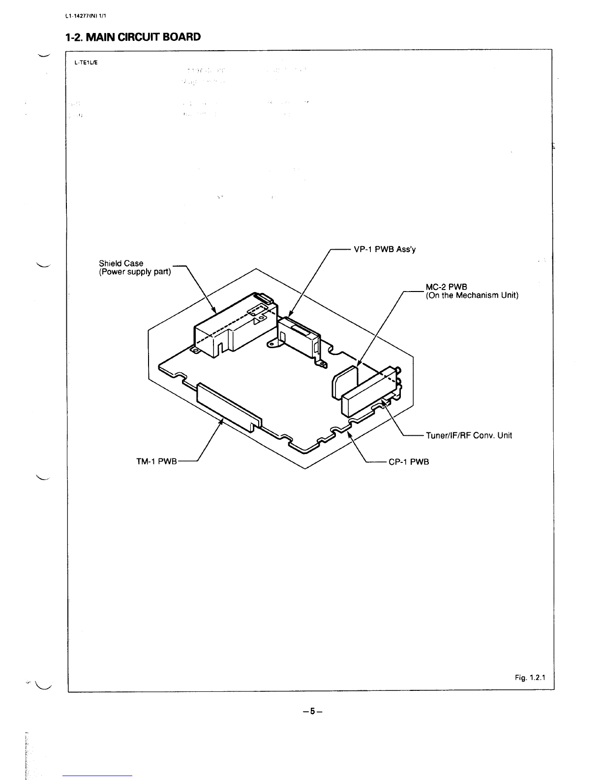
2-2-3. ADJUSTMENT RELAY JIG
Connect the Flat cable end from the Cylinder Ass’y to the
VP-1 PWB Ass’y using the Relay jig to provide simple
repairing and adjustment of the VP-1 PWB Ass’y, as shown in
Fig.2.2.7. Further, when adjusting theVP-l PWBAss’y, be sure
to make contact an end of Shield case with Bracket of the
VP-1 PWB Ass’y to maintain the shield effect. If the VP-1
PWB Ass’y does not contact, there is insufficient ground and
no proper play back image can be obtained.
WPV-TP4/lR BAss’y
\- Uu
Fig. 2.2.7
.Self-recording means “Record the video signal and play
back the just-recorded portion”.
●Connect the monitor TVto the VIDEO OUTPUT terminal,
before making following adjustments.
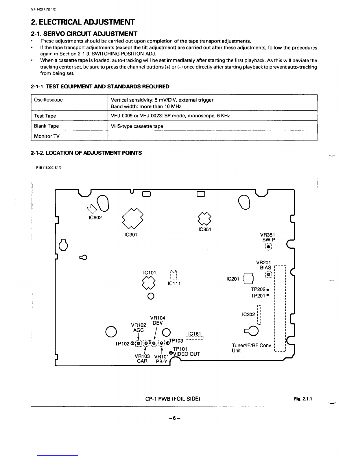
2-2-4. AGC LEVEL ADJ.
Measuring Point MeasuringEquipment ADJ. Condtiion
TPI02 Color bar generator E-E mode
Oscilloscope
(101 probe)
ADJ. Location ADJ. Value
VRI02 (AGC) 0.5Vp-p *0.025Vp-p
1. Connect the color bar generator to the VIDEO INPUT
terminal.
2. AdjustVR102(AGC)for 0,5VP-P* 0.025Vp-p asshown in
Fig. 2.2.8.
WPV-AGC 100% White
A
0.5 Vp-p *0.025 Vp-p
Lr
119
Fig. 2.2.8
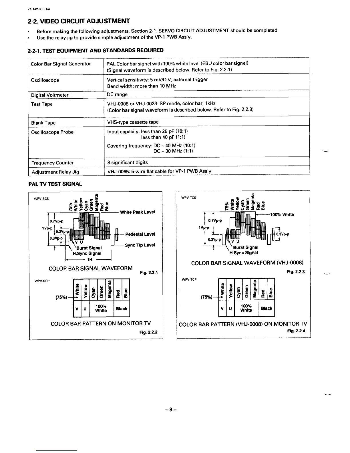
2-2-5. PB-Y LEVEL ADJ. -—
Measuring Point Measuring Equipment ADJ. Condition
TP1OI Oscilloscope PIAY mode
Test tape
(VHJ4XX18 or
VHJ-0023)
ADJ. Location ADJ. Valw
VR1OI (PB-Y) 1Vpp *0.05 Vp-p
1. Play back atest tape.
2. Adjust VRIOI (PB-Y) for the video luminance si9nal level
of 1Vp-p f0.05 Vp-p. (Refer to Fig. 2.2.9)
wPv-PBY 100% White
1Vp-p k
I
~u” Iu u
1- ,,, -1 Fig. 2.2.9
Measuring Point MeasuringEquipment ADJ. Condition
TPI03 Color bar generator REC mode
Frequency counter
ADJ. Location AlXl. Value
VR103(CAR) 3.83 MHz &0.05 Mtiz
.—
1. Connect the color bar generator to the VIDEO INPUT ‘-
terminal.
2. Afier removing the first color bar signal input from the
video inputterminal, immediately adjust VR103 (CAR) so
that the frequency becomes 3.83MHz *0.05 MHz.
–lo–

VI-14285(N)4/4
2-2-7. DEVIATION ADJ.
‘- IMeasuringPoint lMeasuringEquiprnent\ ADJ.Ccmdtiion I
VRI04 (DEV) 1Vp-p *o.05vp-p
1. Record the color bar signal on the blank tape.
2. Play back of the just-recorded portion.
3. Adjust VR104 (DEV) for 1Vp-p *0.05 Vp-p as shown in
Fig. 2.2.10.
4. If the adjustment value is not satisfactory, adjust VRI04
(DEV) and repeat steps 2to 3.
WPV-DEV
bite
1Vp-p
L,H--d
Fig. 2.2.10
2-2-8. Y/C REC CURRENT ADJ.
Meesuring Point MeasuringEquipment ADJ, Condition
TP181 Color bar generator REC mode
(on VP-1 PWB) Oscilloscope Blank tape
(1:1 probe)
ADJ. Location ADJ. Value
VR182(REC-Y/C) ForVHR-3101R/EE/PS:
650mVp-p k 25 mVp-p
ForVHR-310:
550mVp-p k 25 mVp-p
1. Connect the ground of the oscilloscope to the shield case
of the VP-1 PWB Ass’y.
2. Adjust VR182 (REC-Y) so that the video luminance
signal level at the sync tip is Model VHR-31OlR/EE/PS:
650 mVp-p t25 mVp-p, Model VHR-310: 550 mVp-p ~
25 mVp-p. (Referto Fig. 2.2.11)
WV-YREC
———
I
VHR-310 lRIEE/PS:
650 *25 mVp-p
VHR-310:
550 k 25 mVp-p
I1~111111
Sync Tip
Fig. 2.2.11
‘i
._
-11–

A114277(1) 1/2
2-3. AUDIO CIRCUIT ADJUSTMENT
.Before making these adjustments, (especially, the tape “Before making these adjustments, Section 2-1. SERVO
guide height and audio control erase head height adjust- and Section 2-2. VIDEO circuit adjustments should be
ments) should be carried out, so that the tape traveling carried out.
between the loading guide pole and the audio control
erase head runs without fluttering, twisting, curling.
2-3-1. TEST EQUIPMENT AND STANDARDS REQUIRED
Standard Audio Signal Generator (SG)
;?+
Color Bar Signal Generator
Oscilloscope
AC Voltmeter
Blank Tape
Output frequency
Output level
Output impedance
Distotiion ratio
Output in use SG
10 Hz -20 kHz
more than 1Vrms
600 Q
less than 0.1’?4.
Frequency: ..................400 Hz, 10 kHz (switchable)
Output level: ................-33.8 dBs t0.5 dB
Color bar signel with 100% white level.
(Signal waveform is described before. Refer to Fig. 2.2.1)
Vertical sensitivity :10 mV/DIV
Band width :more than 30 MHz
Effective value indication .-
Input frequency :10 Hz -20kHz “;-~~’’?~:
Input Impedance :more than 1MQ
Measurement level :lmV (full scale)
VHS-type cassette tape
2-3-2. LOCATION OF ADJUSTMENT POINTS
PlBl1500C-Al/2
Iclol :...,-:
0
;:
,...:
Iclll
o
‘o uo03
.,..,.
:., Q“
....,,:.
IC602
oCl [
IC351
IC301 VR351
o
SW-P
,....,
:.9.;
aVR201
D
IC201
...
~[
VR104 .,
VR102 ‘Ev :.:
0I
‘r.........0
IC161 a
.............
TP1020;J:10 ;i ~;ie-:OTplOs :---.-......,
,....! ...., ..... ....,’
CAR PB-Y
CP-1 PWB (FOIL SIDE) Fig. 2.3.1
–12–

AI-14285(N)2/2
NOTE:
●Self-recording means ‘Record the audio signal and play
~.- back the just-recorded portion”.
2-3-3. BIAS LEVEL ADJ.
[Al
Measuring point ]Measuring Equipment IADJ. Condition I
TP201 (HOT) Oscilloscope REC mode
TP202 (GND) AC voltmeter Blank tape I
AIM. Location IADJ. Value I
VR201 (BIAS) ]24 mVrms I
1. Load the VCR with ablank tape and select the record
mode without all incoming signal.
2. After confirming on the oscilloscope that a 70 kHz sine
wave is being output, adjust VR201 (BIAS) so that the AC
Lvoltmeter’s reading is 24 mVrms.
[B]
PleasuringPoint Measuring Equipment AW. Condition
AUDIO OUTPUT Oscilloscope Self-recording
terminal AC voltmeter Blank tape
Standard audio signal
generator (SG: signal
-33.8 dBs, 400 tiz
-33.8 dBs, 10 kHz)
ADJ. Location ADJ. Value
VR201(BIAS) -4 dB .+4 dB
between 400 Hz and 10 kHz
1.
2.
3.
4.
5.
6.
7.
Connectthestandard audio signal generatortotheAUDIO
INPUT terminal.
Set the standard audio signal generator’s output level to
-33.8 dBs.
Set the standard audio signal generator’s frequency to
400 Hz and then 10 kHz. Record each of these frequency
signals.
Play back each of the just-recorded portion.
Confirm that the 10 kHz level on AC voltmeter’s reading is
from -4 dB to +4 dB, compared with 400 Hz level.
if the 10 kHz level is less than -4 dB below 400 Hz level or
more than +4dB above 400Hz level, Rotate VR201 (BIAS)
slightly to adjust it.
Repeat steps 3through 6if necessary.
–13–

T.TEIUG(N) 1/1
2-4. TUNER AND IF CIRCUITS ADJUSTMENT
.When any malfunction occurs in the TUNER circuit the NOTE:
whole unit must be replaced.
●An adjustment of the IF circuit is shown as follows.
2-4-1. TEST EQUIPMENT AND STANDARD REQUIRED
The TUNER unit does not need any adjustments,
because precise adjustments have been performed
before shipment.
I
Monitor TV
2-4-2. LOCATION OF ADJUSTMENT POINT
PPFUSOO1O-R1
VR (RF AGC)—
Tuner/l F/RF~
Conv. Unit
r
oRear Panel
o
~CP-I PWB
(PARTS SIDE)
f
IF UNIT Fig.2.4.1
2-4-3. RF AGC ADJ.
Measuring Point Measuring Equipment AIM. Condition
Picture of Monitor TV E-E mode
monitor TV
ADJ. Location ADJ. Value
VR (RF AGC) SIN is best point
(on the IF circuit)
1.
2.
3.
4.
Connect the monitorlV to VHF/UHF ANTENNA OUTPUT –
terminal.
Connect the VHF antenna to VHF/UHF ANTENNA INPUT
terminal.
Receive the middle electricalfield(70 dB~ -90 dB@ of the
VHF high channel, and slowly turn VR (RF AGC) from the
point where snow-noise is present to the point where it
just disappears from the monitor TV.
Confirm by monitor TVthatthere is no beat and saturation
(S/N is best point) when receiving any TV channel.
3.TEST POINT FORTAPEPATHADJUSTMENT
Test point TP182 (ENV) and TP183 (SW-P) for tape path adjustment isshown in Figure below.
For adjustment, refer to the Mechanism Service Technical lnformation(WM-530599 and MS531206).
P1B08800C-T3
Shield case
o
Y\] “
@l
.- 0
———
TP181
REC Current
TP1S3 SW-P ~/
TP182 ENV ~
\VR182 REC-YJC
VP- IPVVBASS’Y Fig.3.1
–14–

4. PARTS LIST
LOC~TION PORTS NO.
ACCESSORIES
OR
OR
OR
OR
OR
OR
OR
OR
OR
OR
OR
OR
OR
6450024689
613 14735’$’1
A6130950550
A6131332393
A6450026805
A6450033766
613 1487918
613 1487963
613 1504486
613 1470958
613 1207936
i6130105936
6130966773
613011 7359
613 1326132
613 1325975
A6450027642
A6131366411
A6131407473
DESCRIPTION
REtlOCON(WITH COVER BATTERY)
COUER B~TTERY(FOR REMOCON)
CORO?POWER(VHR-31OEE,31OPS)
CORD?POWER(VHR-310EE,31 OPS)
CORD,POWER(VHR-31OEE,31OPS)
CORD?POWERKJHR-310EE,31 OPS)
INSTRUCTION MLiNU~L(VHR-310 ONLY)
INSTRUCTION tl/$NU~L(VHR-3101R ONLY)
INSTRUCTION fl~NU~L (VHR-31 OEE ONLY)
INSTRUCTION MI3NUQL(VHR-31OPS ONLY)
OLMPTER,OC(VHR-31OPS ONLY)
PLUG(VHR-31OPS ONLY)
CABLE,6NT(EXCEPT VHR-31OIR)
CORD(EXCEPT VHR-31OIR)
COBLE,ANT
CORO
CORD,POWER(VHR-31O ONLY)
CORO,POWER(VHR-31OIR ONLY)
CORD,POWER(VHR-31OIR ONLY)
**%******* %***#********** ***** *$*** **%** x**********************
PACKINGMATERIALS
613 151 0678 CARTON CASE(UHR-31O ONLY)
OR 613 15i 6335 CARTON CASE(UHR-31OIR ONLY)
OR 613 1522121 CARTON CASE(VHR-31OEE ONLY)
OR 613 151 0685 CARTON CASE(VHR-31OPS ONLY)
613 1502291 CUSHION,FRONT(VHR-31O,31OIR)
Undesignated numerel shows
Location No.:CH-
N.S.P. :Not availableasserviceDarts
LOCATION PARTS NO. DESCRIPTION
613 1485174 CUSHION,FRONT(VHR-31OEEt31OPS)
613 1502307 CUSHION,BACK(VHR-310,31OIR)
OR 613 1485181 CUSHION,BACK(VHR-31OEE,31OPS)
613099 1768 POLYE COVER,INNER-K
%****%***********%*x*********************************%%%*******
CABINET&CHASSISPARTS
CH-1
CH-2
CH-3
CH-4
CH-5
CH-6
CH-7
CH-8
CH-10
OR
OR
OR
CH-11
OR
CH-12
CH-14
CH-15
CH-16
CH-17
CH-18
OR
OR
411 1370007
411 021 7907
411 027 1701
613 1465749
4120289406
613 1402175
411 021 3800
613 1462960
613 151 0401
613 151 5758
613 152 1483
613 151 0395
6450029608
6450022661
613 1392182
613 121 1001
613 1464261
613 1472563
613 1407459
613 1483293
613 1509467
613 151 0616
SCR L-TPG BIN 3X1O
SCR S-TPG BIN 4X12
SCR S-TPG BIN 3X1O
COMPL PUB,VP-1
SPECIAL SCREW
COVER TOP
SCR S-TPG BIN 3X1O
TERMINAL
CC!flPLPWB,CP-1-A(VHR-31O ONLY)
COMPL PWB,CP-1-A(VHR-31OIR ONLY)
COMPL PWB,CP-1-A(VHR-31OEE ONLY)
COMPL PWB,CP-1-A(VHR-31OPS ONLY)
TuNERPRF/Tu/IF(vHR-310,310Ps)
TuNER.RF/Tu/IF(vHR-3101R,310EE)
COVER BOTTOM
STANO,FELT,FRONT
COMPL PWB,TM-1
OOOR CASSETTE
SPRING
ASSY,CABINET FRONT(UHR-310.31OIR)
ASSY.CABINET FRONT(VHR-31OEE ONLY)
ASSY,CABINET FRONT(VHR-31OPS ONLY)
EEl
–15–

MECHANISM PARTS
LOCATION Pf2RTSNO.
tIIECHANISMPARTS1
OR-1
OR
OR
OR-2
OR
OR-3
OR
OR-4
OR
OR
OR-5
OR-6
OR
OR-7
OR-8
OR
OR-9
OR
OR-10
OR
OR
OR-11
OR-12
OR-13
MB-1
MB-2
MB-3
MB-4
MB-5
MB-6
MB-7
MB-8
MB-9
MB-10
MB-11
MB-12
MB-13
MB-14
MB-15
MB-16
MB-17
MB-18
MB-19
MB-20
MB-21
MB-22
MB-23
MB-24
OR
MB-28
MB-29
MB-30
MB-31
MB-32
MB-33
MB-34
MB-35
MB-36
MB-37
MB-38
MB-39
613 113 1323
6130788665
613 150 7159
411 038 1608
412048 1503
6130788672
613 1507166
613 113 1354
6130220271
613 150 7173
613081 4036
6130889072
613022 1001
411 047 7509
411 047 5000
412 030 9708
613085 7279
613 132 3520
411 044 8301
411 044 9209
4120360709
6130224019
411 044 9001
613 151 0470
613 123 4802
6130533227
613 123 4970
411 004 5302
613 1239418
613021 9961
613021 9800
411 109 2008
613022 1797
613 144 5741
613 110 1692
412 0158207
411 1200007
613 1203631
613022 1582
613094 9240
613022 1575
613022 2725
6130222534
613094 1206
613 1342910
411 046 8002
411 0232801
411 0233303
411 021 3107
613077 3227
613027 0382
6130788320
613 1170599
6130939159
613093 8374
6130773616
613 121 9960
6130929945
613 132 8075
613 1438439
613 1100374
DESCRIPTION
COMPL,CYLINOER,2N2P-V
(EXCEPT UHR-31O)
COMPL,CYLINOER,2N2P-V
(EXCEPT UHR-31O)
COMPL,CYLINOER,2N2P(UHR-31O ONLY)
SCR PAN+W 3X8(EXCEPT UHR-31O)
SPECIOL SCREW 2.6X8(VHR-31O ONLY)
ASSY,CYLINOER,UPR 2N2P-V
(EXCEPT VHR-31O)
ASSY,CYLINOER,UPR 2N2P
(VHR-31O ONLY)
IISSY,CYLINOER,LWR 2AL
(EXCEPT VHR-31O)
OSSY,CYLINOER,LWR 2(EXCEPT VHR-31O)
ASSY,CYLINOER,LWR 2(VHR-31O ONLY)
SPACER,MOTOR O.3T
BASE,CYLINDER
BASE,CYLINDER
SCR PAN+FLG 3X6
SCR PAN+FLG 2.6X8
SPECIAL SCREW 2.6X8
STATOR,MOTOR CYL(EXCEPT VHR-31O)
STATOR,MOTOR CYL
SCR PAN+SW 2.3X1O
SCR PAN+SW 2.3X8
SPECIAL SCREW 2.3X1O
ROTOR,MOTOR CYL
SCR PAN+SW 2.3X6
PWB,CYLINOER(VHR-31O ONLY)
SLEEVE
SPECIAL WASHER
TAPE GUIOE
NUT HEX (3)
CAP
ASSY,SLIOE,ACT PINCH
ASSY,LEVER,CAM PINCH
WASHER Y 3.1X8X0.5
SPRING,ACE HEAO
COMPL,BRACKET,HEAO
SLEEVE,ACE HEAO
SPECIAL NUT (M5)
SCR PAN+SW+W 2.6X5
BRACKET,STOPPER
SPRING,SLIOE BRAKE
COMPL,SLIOE,CAM
SPRING,LINK LOCK
OAMPER
GEAR,FRONT LOAO
ASSY,LEVER,FRONT
GEAR,HELICAL FRONT
SCR P9N+SW+W 2.6X6
SCR S-TPG PAN 2.6X6
SCR S-TPG PAN 2.6X8
SCR S-TPG BIN 2.6X8
HOLOER,WORM
WASHER
ASSY,WORM,FRONT
BRACKET.HOLOER
PLATE,NUT
OAMPER,MOTOR
OAMPER,WORM
ASSY,LOGOING MOTOR
OAMPER,MOTOR
COMPL PCB,MC-3
COMPL PWB,MC-2
ROTARY SWITCH
LOCATION
MB-40
MB-41
MB-42
MB-43
nB-44
OR
MB-45
MB-46
MB-47
MB-48
MB-49
MB-50
MB-51
MB-52
MB-53
MB-54
MB-55
MB-57
MB-58
MB-59
MB-60
MB-61
MB-63
MB-66
MB-67
MB-90
PARTS NO.
411 1265303
6130929921
6130925985
6130925992
613092 5886
613 1388628
6130270627
6130929938
6130222985
4120334106
6130773579
613 1029293
613022 1568
6130220158
613 1479951
411 1092107
6130788160
613 1357655
613 1455009
613 1455016
411 0630904
6130220233
6450002533
613 153 1871
613022 1698
613 1444577
E--l
DB80823B
MBoo15##
DESCRIPTION
SCR PAN 2.6X13
ASSY,SLIOE,FRONT
SPRING,LEVER LOAO
SPRING,LEVER ACT
HOLDER,WORfl
HOLOER,WORM
WASHER 2.1X6X0.5
ASSY,WORM,LOAO
BELT,LOhOING
WASHER SLIT 2.6X5X0.50
GEAR,HELICAL
ASSY,LEUER,REV GUIOE
SPRING,REVIEW LEVER
COMPL,PINCH ROLLER
SPRING,PINCH ROLLER
WASHER Y 3.6X6X0.5
COMPL,LEVER,/ICTBRAKE
PLATE,BGR
ASSY,MOUNTING,ROLLER S
ASSY,MOUNTING,ROLLER T
SCR SET HEX-SCT 2X3
ASSY,GUIOE,ROLLER
HEAO,FULL ERASE
LEVER,FE HEAO -d
SPRING.ERASE HEAO
FLEXIBLE FLAT CABLE,CN811-CN303
14ECHANISIIPARTS2
MC-1
MC-2
MC-3
MC-6
MC-7
MC-8
nc-9
MC-10
MC-12
tlc-13
MC-14
MC-15
MC-16
MC-17
MC-18
MC-19
MC-20
MC-22
MC-23
MC-24
MC-25
MC-26
MC-27
MC-28
MC-29
MC-30
MC-31
MC-34
MC-35
MC-36
MC-37
MC-38
MC-40
MC-41
6450005053
6130222978
613 1354609
613022 1520
6130823434
613022 1711
613081 7518
6130982285
411 021 3107
411 1092008
613 1429093
613022 2701
411 109 1902
613 1357686
613 1357532
411 109 1803
613 1357648
411 047 6809
613021 9763
613 1357662
613022 1551
613021 9879
6130906373
613022 1704
613021 9862
6130222039
613091 3104
411 0286309
4120158603
613 1309890
4120454606
411 0920906
411 1000300
613 1209060
MOTOR,CAPSTAN OC 3W
BELT,REEL ORIVE
COMPL,LEVER,CLUTCH
SPRING,LEVER CLUTCH
LEVER,CHANGE CLUTCH
SPRING,CHANGE CLUTCH
(ISSY,BRAKE CAPSTAN
SPRING,CAPSTAN
SCR S-TPG BIN 2.6X8
WASHER Y 3.1X8X0.5
SLIOE,CAM PLATE
CAM,MOOE
WASHER Y 3.1X6X0.5
CAM,MAIN
ASSY,RACK,LOAO
WASHER Y 2.6X6X0.5
SPACER,RACK LOAO
SCR PAN+FLG 3X4
ASSY,EARTH,CYL
GEAR,LOAO TAKE UP
SPRING,GEAR LOi40T
ASSY,LEVER,LOAO T
GEAR,LOAO S
SPRING,GEAR LOAO S
ASSY,LEVER,LOAO S
LEVER,RETURN TENSION
ASSY,LEVER CONTROL
SCR S-TPG PAN 2.6X6
SPECIAL WASHER 3.1X6X0.25
ASSYrGEAR,FRICTION
SPECIAL WASHER 2.4X6X0.25
WASHER Z 2.6X1OXO.5
SCR S-TPG BIN 2.6X5
COMPL,MC-1
_.
–16–

MECHANISM PARTS 1
MECHANISM PARTS 2
Undesignetsd numeral shows
Location No.:MC- 1249
41
&+34 ---4 ‘J
N.S. P.:Not available as service parts
–17–

LOCATION PORTS NO.
14ECHANISMPARTS3
co-1
ccl-4
co-5
CO-6
co-7
CD-8
co-9
co-lo
Co-n
CO-12
CO-13
CD-14
CO-15
CO-16
CO-17
CO-18
CO-19
CO-20
CO-21
co-22
CO-24
CO-27
CO-28
CO-31
MA-1
MA-2
MA-3
MA-4
MA-5
HA-6
OR
MA-7
OR
1.
613 1429581
6130220585
4070983201
411 0159801
613022 1643
6130220073
6130222695
613 141 6109
613 1398962
6130222626
613021 9657
411 027 1305
6130950949
411 1069208
6130220943
6130222619
613022 1667
6130222596
6130220097
613022 1674
6130224064
613 124 5006
613 1256149
411 001 8702
613 1000391
6130857996
613021 9701
411 144 2803
411 109 1605
613 135 7068
613 135 7549
613 135 7075
613 143 2963
DESCRIPTION
COMPL,CASSETTE MECHANISM
LIO
PHOTO COUPLE PN150SflN
RING E 2.3
SPRING,LINK L
ASSY,GEAR,LEUER L
RACK
GEAR.LOCK
ASSY,LEUER,PINION
GEAR,PINION
ASSY.BRACKET,GEAR
SCR S-TPG BIN 2.6X4
SW,SPECIAL
SCR PAN+SW+W 2X9 ..;
i
HOLDER.TRANSISTOR ,,
GEAR,IOLER
SPRING,GEAR MAIN .,
GEAR,tlAIN
ASSY,GEAR.LEUER R
SPRING,LINK R
BOARO,UNOER .<
LEUER,SAFETY SW L.,
SPRING,SAFETY SW .,
..
SCR BIN 3X6
ASSY,LEUER,TENSION
SPRING,LEVER TENSION ‘
ASSY,HOLOER,BANO
SCR PAN+SW+W 2.6X6
WASHER Y 2.6X6X0.25
OSSY,REEL,SUPPLY
ASSY,REEL,SUPPLY
ASSY,REEL,TAKE UP
ASSY)REEL,TAKE UP
LOCATION
MO-8
OR
OR
MA-9
OR
MA-10
OR
MA-11
MA-12
OR
MA-15
MA-16
MA-17
MA-18
MA-19
MA-20
MA-21
MA-22
MA-23
MA-24
MA-25
M&-26
MA-27
MA-28
MA-29
MA-30
MA-31
MA-32
MA-33
MA-34
MA-35
MA-36
MA-37
MA-38
MA-39
PARTS NO.
412021 5306
4120158900
4120158504
411 109 1506
411 109 1407
613 1357150
613 1429116
4120267305
613 1357167
613 1429109
4120424302
613 1357099
411 120 1301
613 1357082
411 021 3107
613 1209053
4070167205
613021 9985
613 1429086
613022 1612
613022 1506
6130980106
6130773647
613022 1490
6130222374
6130848871
6130220004
6130809216
4130862914
6130809209
411 1093005
6130222015
4120159501
411 021 7907
4120454606
Ii
CB602700
MBOO15##
DESCRIPTION L.
SPECIAL WASHER 3.1X6X0.3
SPECIAL WASHER 3.1X6X0.4
SPECIAL WASHER 3.1X6X0.5
WASHER Y 2.1X6X0.25
WASHER Y 2.1X5X0.25
GEAR,REEL SUPPLY
GEAR,REEL SUPPLY
SPECIAL WASHER 2.6X6X0.25
GEAR,REEL TAKE UP
GEAR,REEL TAKE UP
SPECIAL SCREW 2.6X4
COMPL,IOLER,CLUTCH
WASHER Y 2.1X4X0.25
ASSY,IOLER
SCR S-TPG BIN 2.6X8
COtlPLPCB,MC-4
LEO LN59
ASSY,SLIOE,ACT PLATE
SLIOE,C BRAKE
SPRING,RETURN SLICIE
SPRING,SUB T
ASSY,BRAKE SUB T
PULLEY,REEL
SPRING,SUB SUPPLY
SLIOE,ACT BRAKE
BRAKE,SUB SUPPLY
ASSY,SLIOE,M PLATE
OSSY,BRAKE,SUPPLY
SPRING,MAIN BRAKE
ASSY,BRAKE,TAKE UP
WASHER Y 2.6X5X0.5
LEVER,CONT PLATE
SPECIAL WASHER
SCR S-TPG BIN 4X12
SPECIAL WASHER 2.4X6X0.25
-
Undesignated numeral shows
Location No.:MA- 9--15
54
,-
. . . . . . . ----
28
N.S.P.:Not available as service parts
-39 -a
–18–

ELECTRICAL PARTS
NOTE;
1. Materials of Capacitors and Reaiatora are abbreviated aa follows;
Reaietora
MT-FILM Metallized Film Reaiator
MT-GLAZE Metallized Glaze Reaiator
OXIOE-MT Oxide Metallizad Film Reaiator
Capacitor
MT-POLYEST Metallized PolyesterCapacitor
MT-COMPO Metallized CompositeCapacitor
TA-SOLID Tantalum Solid Capacitor
AL-SOLID Aluminum Solid Capacitor
NP-ELECT Non-Polarized Electrolytic
Capacitor
OS-SOLID Aluminum Solid Capecitora with
Organic Semiconductive
Electrolytic Capacitw
DL-ELECT Double Layered Electrolytic
Capacitcx
2. Tolerance of Capacitor(l OpF over) and Reaiator are noted with follow eymbolea.
F............*lVO G.........-..*2’VO J............*5% K-....=..-*1O%
M............*20% N ............*30% z-...........+80% -–20%
3. Capecitofa
U:UF P:PF
4. Inductors
UH :uti MH :mH
5. N.S.P. :Not available aa eervica parts.
LOCATION PARTS NO.
C611PLPHB,CP-I-A
COMPL.NO 613 151 0401
COtlPL.NO 613 151 5758
COMPL.NO 613 152 1483
COMPL.NO 613 151 0395
(SEHIC~NDUCT6RS)
Q1OO2
OR
OR
OR
Q1OO3
OR
OR
OR
Q1OO4
OR
OR
OR
Q1OO6
OR
OR
OR
Q1011
OR
Q1012
OR
OR
OR
Q1014
OR
OR
OR
Q1151
OR
Q1152
OR
Q1601
OR
Q1721
OR
OR
4050576201
4050576409
405 123 7002
405 123 7101
405 064 0100
405 0640209
405 123 6708
405 1236807
405064 0100
4050640209
405 1236708
405 1236807
405 057 6201
405 057 6409
405 1237002
405 123 7101
405 063 9708
405 1236500
405 057 6201
4050576409
405 123 7002
405 123 7101
405 057 6201
405 057 6409
405 123 7002
405 1237101
4050639708
405 1236500
4050639302
405 1242808
405004 4601
405006 1806
4050160905
405016 1100
4050129506
DESCRIPTION
(UHR-31O)
(UHR-31OIR)
(VHR-31OEE)
(UHR-31OPS)
TR 2SC4038-Q-TL2
TR 2SC4038-R-TL2
TR 2SD1991A-Q-(TA)
TR 2S01991A-R-(TA)
TR 2SA1561-TL2-Q
TR 2SA1561-TL2-R
TR 2SB1320A-Q-(TA)
TR 2SB1320A-R-(TA)
TR 2SA1561-TL2-Q
TR 2SA1561-TL2-R
TR 2SB1320A-Q-(TA)
TR 2SB1320A-R-(TA)
TR 2SC4038-Q-TL2
TR 2SC4038-R-TL2
TR 2SO1991O-Q-(TA)
TR 2S01991A-R-(TA)
TR 0TC144EL-TL2
TR UN6213-(TFl)
TR 2SC4038-Q-TL2
TR 2SC4038-R-TL2
TR 2SD1991A-Q-(TA)
TR 2S01991(I-R-(TA)
TR 2SC4038-Q-TL2
TR 2SC4038-R-TL2
TR 2S01991A-Q-(TA)
TR 2SO1991#I-R-(TA)
TR 0TC144EL-TL2
TR UN6213-(TA)
TR DTA124EL-TL2
TR UN6112-(TA)
TR 2SA608-F-SPA-AC
TR 2SA933S-T93-R
TR 2SC2839-E-SPA-AC
(UHR-31OEE,31OPS)
TR 2SC2839-F-SPA-AC
(VHR-31OEEP31OPS)
TR 2SC2058S-OCTP-Q(UHR-31OEE,31OPS)
LOCATION
Q2001
OR
OR
Q2002
OR
Q2003
OR
Q3001
OR
Q3002
OR
Q3504
OR
Q5101
OR
Q5102
OR
OR
Q5103
OR
Q6001
OR
OR
OR
OR
OR
OR
Q6002
OR
Q6004
Q6005
OR
Q6601
OR
Q6901
OR
OR
OR
OR
Q6902
OR
–19–
PARTS NO.
4050180002
4050180101
4050180200
4050639708
405 1236500
4050037702
405000 1208
4050638404
405 1236302
4050638404
405 1236302
4050639708
405 1236500
4050044007
4050044601
4050892103
405 1074201
405 1074102
4050182808
4050003103
4050269004
4050269103
405 1147806
405 1147905
405 1148001
4050736407
4050736506
4050182501
4050006104
4050189500
4050037603
4050002205
4050182501
4050006104
4050192005
405011 8401
4050930607
4050192807
405011 8500
4050044007
405006 1707
DESCRIPTION
TR 2SC3331-S-AA
TR 2SC3331-T-AA
TR 2SC3331-U-Afl
TR OTC144EL-TL2
TR UN6213-(TA)
TR 2SA1346-AC
TR 0TA124ES-OCTP
TR DTC114EL-TL2
TR UN6211-(TA)
TR OTC114EL-TL2
TR UN6211-(TA)
TR OTC144EL-TL2
TR UN6213-(TA)
TR 2SA608-E-SPA-AC
TR 2SA608-F-SPA-AC
TR 2SC4483-S-AN
TR 2S01994-S (TA)
TR 2S01994-R (TA)
TR 2SC3402-AC
TR OTC114ES-OCTP
TR 2SK222-O-AA
TR 2SK222-E-AA
TR 2SK1104-(TA) P
TR 2SK1104-(TA) Q
TR 2SK1104-(TA) R
TR 2SK772-E-AC
TR 2SK772-F-AC
TR 2SC3399-AC
TR 0TC144ES-OCTP
TR 2SC3901-AC
TR 2SA1345-AC
TR DTA144ES-OCTP
TR 2SC3399-AC
TR 0TC144ES-OCTP
TR 2SC536-E-SPA-AC
TR 2SC1740S-OCTP-Q
TR KSC2785-Y
TR 2SC536-F-SPA-AC
TR 2SC1740S-OCTP-R
TR 2SA608-E-SP9-AC
TR 2SA933S-TP-Q

LOCATION PARTS NO.
Q6902 4050930508
OR 4050044601
OR 405 006 1806
Q6903 405 019 2005
OR 405 011 8401
OR 405 0930607
OR 4050192807
OR 405 011 8500
Q6904 405 018 2501
OR 405 000 6104
Q6921 405084 8209
OR 4050848308
(INTEGRATEDCIRCUITS)
Iclol
IC1ll
IC161
OR
IC171
IC201
IC301
IC302
IC303
OR
IC351
OR
OR
IC501
IC511
IC512
IC602
OR
OR
OR
OR
IC691
IC692
OR
(D16DES)
01003
OR
01006
OR
01007
OR
01008
OR
01201
OR
01601
OR
01602
OR
01612
OR
01613
OR
03001
03002
OR
03003
OR
4093036700
4092976205
4090034501
409 120 3401
4090034907
409 262 2409
410 1749806
409 114 4803
4092434200
4090323704
409 306 0408
4093060507
409311 9601
409 297 7509
409 067 7203
4092977400
409 270 0008
409 247 7702
409283 5403
410 172 6807
410 172 6708
409 019 6209
409 026 8203
4090575103
407 007 9904
407 012 4406
407 007 9904
4070124406
407 007 9904
407 012 4406
407 007 9904
407 012 4406
407 007 9904
407 012 4406
407 007 9904
407 012 4406
407 007 9904
4070124406
407 0079904
4070124406
4070079904
4070124406
407 1507703
407 099 5303
407 051 6904
407 063 9504
407 070 8101
DESCRIPTION
TR KSA1175-Y
TR 2SA608-F-SPA-AC
TR 2SA933S-T93-R
TR 2SC536-E-SPA-AC
TR 2SC1740S-OCTP-Q
TR KSC2785-Y
TR 2SC536-F-SPA-AC
TR 2SC1740S-OCTP-R
TR 2SC3399-AC
TR DTC144ES-OCTP
TR 2SC2960-F-SPA-AC
TR 2SC2960-G-SPA-AC
Ic LA7345M
IC LC89925
IC BA7021
IC LA7221
IC BA7025L(UHR-310EE,31OPS)
IC LA7285M
IC LC866124V-5396
IC LB1641
IC MN1380-R
IC MN1280-R
IC XRU2890BK
IC BU2890BK
IC BU28900K
IC STR-M6549
IC L5431-AA
IC PQ12SZ11
IC ST24C01B1
IC ST24C02AB1
IC LE24C01S1
IC X24C02P-C7189
IC X24C01AP-C7284
Ic LA791o
IC L5631
IC UPC574J
OIOOE GMAO1-BT
OIOOE 1SS133-T-77
OIOOE GMAO1-BT
OIOOE 1SS133-T-77
OIOOE GMAO1-BT
OIOOE 1SS133-T-77
OIOOE GMAO1-ET
OIOOE 1SS133-T-77
OIOOE GMAO1-BT(UHR-310EE,31OPS)
OIODE 1SS133-T-77(VHR-31OEE,31OPS)
OIOOE GMAO1-BT
OIOOE 1SS133-T-77
OIOOE GMAO1-ET
OIODE 1SS133-T-77
OIODE GMAO1-ET
OIOOE 1SS133-T-77
OIODE GMAO1-ET
OIOOE 1SS133-T-77
OIOOE RB441Q T-77
ZENER OIOOE MTZJ5.6B-T-77
ZENER OIOOE GZS5.6Y-BT
ZENER OIOOE MTZJ8.2B-T-77
ZENER OIOOE GZS8.2Y-BT
LOCATION PARTS NO.
03005 4070079904
OR 4070124406
03121 4070079904
OR 4070124406
03122 4070079904
OR 4070124406
03123 4070079904
OR 4070124406
03124 4070079904
OR 4070124406
03125 4070079904
OR 4070124406
03502 4070079904
OR 4070124406
D5001 407 134 8900
05003 407091 6704
05004 4070782705
05011 A 407 151 3308
05101 407 1292005
05102 407 158 1505
05103 407 1006909
OR 407091 6902
05104 4070782705
05105 407 1006909
OR 407091 6902
05109 4070995105
05110 407 1205807
05111 4070079904
OR 4070124406
05112 4070638705
05113 4070049709
OR 4070058701
05114 4070782705
06901 4070124406
OR 4070079904
06902 4070124406
OR 407 007 9904
06903 4070124406
OR 4070079904
(CRYSTALDEVICES)
Xlool 6450006012
OR 6450006029
X3001 6450035852
OR 6450034510
X3002 613 1090972
OR 613 1236387
(CERAllICRES6NAT6RS)
XF171 613084 1681
XF172 6130158604
(VARIABLERESISTGRS)
VR101 613 1208438
OR 613 1208582
VR102 613 1208421
OR 613 1208575
VR103 613 1208438
OR 613 1208582
VR104 613 1208438
OR 613 1208582
UR201 6130977915
OR 613001 9097
DESCRIPTION
OIOOE GMAO1-ET —
OIOOE 1SS133-T-77
DIOOE GMAO1-BT
DIODE 1SS133-T-77
OIOOE GMAO1-ET
OIOOE 1SS133-T-77
OIODE GMAOI-ET
OIOOE 1SS133-T-77
OIOOE GMAO1-ET
OIOOE 1SS133-T-77
OIODE GMAO1-ET
OIOOE 1SS133-T-77
OIOOE GMAO1-ET
OIOOE1SS133-T-77
OIOOE OBC1OG
OIOOE APO1C-VO
OIOOE 1SS244-T-77
PHOTO COUPLE PC120FB
OIODE RL2Z-LF-B1
DIOOE ERC30-02L38
OIOOE AGO1-U2
OIOOE ERA38-04-V5
OIOOE 1SS244-T-77
OIOOE AGO1-V2
OIOOE ERA38-04-V5
ZENER OIOOE MTZJ4.7B-T-77
OIOOE AK04-V2
OIODE GMAO1-ET
OIOOE 1SS133-T-77
ZENER OIOOE MTZJ5.1C-T-77
DIODE DSK1OC-BT
OIOOE ERA15-02-U5
OIOOE 1SS244-T-77
DIOOE 1SS133-T-77
DIOOE GMAO1-ET
OIOOE 1SS133-T-77
OIOOE GMAO1-ET
OIOOE 1SS133-T-77
OIOOE GMAO1-ET
OSC,CRYSTAL 4.433619MHZ
OSC,CERAMIC 13.31MHZ
OSC,CRYSTAL 32KHZ
OSC,CRYSTAL 32.768KHZ
FILTER 4.16MHZ 8.F(VHR-31OEE,31OPS)
CHOKE COIL(VHR-310EE,31OPS)
VR,SEMI 22KB
VR,SEMI 22KB
UR,SEMI 2.2KB
VR,SEMI 2.2KB
VR,SEMI 22KB
VR,SEMI 22KB
VR,SEMI 22KB
UR,SEMI 22KB
VR,SEMI 100KB
SEMI UR 100KB
–20–
Other manuals for VHR-310
1
This manual suits for next models
3
Table of contents
Other Sanyo VCR System manuals

Sanyo
Sanyo VWM-950 User manual

Sanyo
Sanyo VHR-VX700 User manual

Sanyo
Sanyo VHR-330EV User manual

Sanyo
Sanyo SRT-8960P User manual

Sanyo
Sanyo VHR-M262EV User manual

Sanyo
Sanyo VHR-590 User manual

Sanyo
Sanyo VHR-495E User manual

Sanyo
Sanyo SRT-2400 User manual

Sanyo
Sanyo VHR-420 User manual

Sanyo
Sanyo VHR-VX600 User manual

Sanyo
Sanyo TLS-1500P User manual

Sanyo
Sanyo VHR-290 Series User manual

Sanyo
Sanyo VHR-VK910A User manual

Sanyo
Sanyo SRC-850A User manual

Sanyo
Sanyo VHR-489SP User manual

Sanyo
Sanyo VHR-H531 User manual

Sanyo
Sanyo VHR-899E User manual

Sanyo
Sanyo TLS-4024P User manual

Sanyo
Sanyo VHR-288E User manual

Sanyo
Sanyo VHR-7100 User manual