Sargent and Greenleaf 6125 User manual

MOUNTING CONSIDERATIONS
• Sargent & Greenleaf 6100 series Motorized Electronic Combination Locks have been designed to
use the same mounting screw locations and occupy the same space as a
standard S&G 6730 mechanical lock. The 6100 series uses standard
mounting dimensions to simplify retrofit in existing safes.
• The keypad diameter is 4 inches (101.6mm). This is slightly greater
than the diameter of standard S&G dial rings for
mechanical locks. The 61KP series key-
pad will cover any scratches or paint
blemishes left by the old lock.
• Modifications to the lock are not rec-
ommended, and will void the manu-
facturer’s warranty.
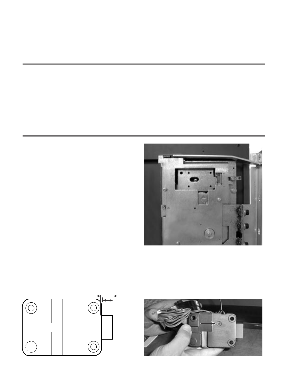
• The 6125 and 6127 locks are
designed to have boltwork blocking
devices attached to the end of the lock bolt. These two locks are designed to move a 2.25 lb. (10
newton) load. The maximum intermittent load must not exceed 5.5 lbs. (25 newtons).
• The direction of movement of the device attached to the end of the lock bolt must be in line with the
direction of movement of the lock bolt. Any misalignment will adversely affect performance.
• The 6125 and 6127 locks require installation of a microswitch (not included), which activates
extension of the lock bolt.
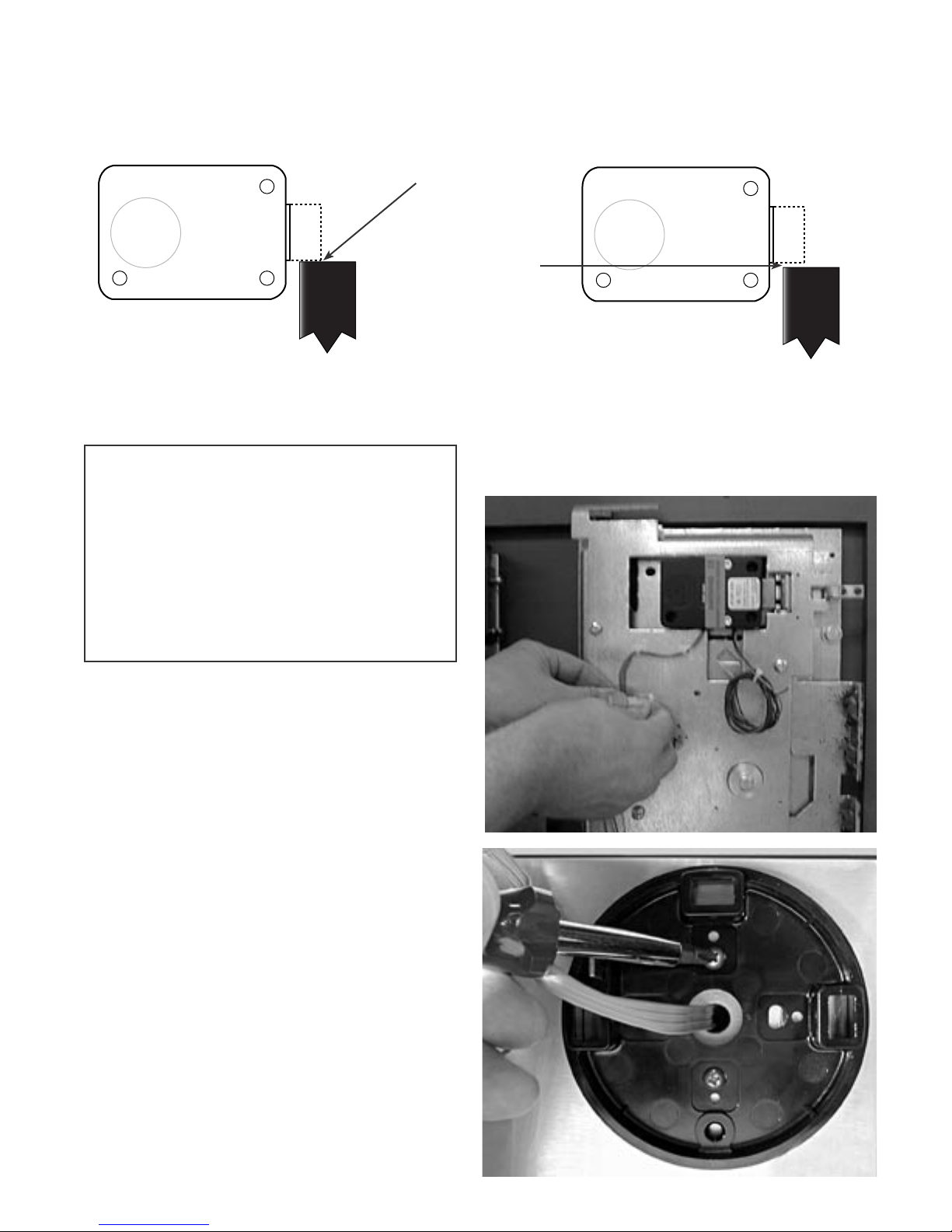
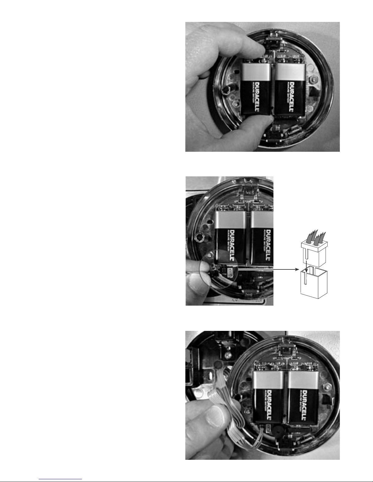
• You should install fresh alkaline batteries in the keypad and connect the lock wiring cable to
check the functions of the lock prior to installation. Follow the procedures given in the Operating
Instructions.
• If you are installing a 6127 and will be adding the audit trail/alarm interface, you should also read
those instructions (document 630-523) before beginning the lock and keypad installation.
Sargent & Greenleaf, Inc.
One Security Drive, Nicholasville, Kentucky 40356
Phone (859) 885-9411 FAX (859) 887-2057
Copyright 1998, Sargent & Greenleaf, Inc. This document is part number 630-429
revised 7/9/00
Installation
Instructions
6125/6127
Motorized Electronic
Combination Lock
Sargent & Greenleaf S.A.
9, chemin du Croset, 1024 Ecublens, Switzerland
Phone 41-21-691-9583 FAX 41-21-691-5349
This Sargent & Greenleaf 6100 series electronic lock combines ease of operation with security.
Advanced electronic circuit design makes it easy to install, easy to open, and easy to change
codes. Follow these instructions carefully to get the best possible performance from your lock.

INSTALLATION NOTES . . .
Although the model 6100 series is easy to install, we recommend the following procedures be
performed only by an experienced locksmith or safe technician. Your safe may incorporate relock-
ing devices that are attached to the combination lock. Misalignment or detachment of these
devices can result in a lockout—a condition where the safe cannot be opened without damage.
ADDITIONAL ITEMS YOU WILL NEED . . .
The 6100 series requires two 9-volt alkaline batteries (not included). We recommend fresh
Duracell® batteries. Do not use old or partially drained batteries in your lock. New batteries will
power your lock for approximately 5,000 openings when used without the time delay feature.
Many installations can be performed with nothing more that a medium phillips screwdriver. If the
manufacturer of your safe has made external relock device attachments to the lock, specialized
tools and knowledge may be required.
INSTALLATION . . .
Step 1
Remove the existing lock (if present). The
mounting plate should be smooth and flat,
with 1
⁄4-20 (M6) mounting screw holes.
The wire channel (spindle hole) must have a
diameter of at least 5
⁄16 inch (8 mm).
The 6100 series can be mounted right-
hand, left-hand, vertical-up, or vertical-down
without any modifications or adjustments.
Step 2
Determine the bolt throw required for this application. If it’s more than .46” (11,7 mm),
remove the bolt travel adjustment screw and add the enclosed .075” (2 mm) thick spacer
when attaching the safe’s boltwork to the lock bolt.
Standard bolt extension:
Locked = .461” (11,71 mm)
Unlocked = 0 (flush with case)
Throw = .461 (11,71 mm)
Travel screw removed:
Locked = .461” (11,71 mm)
Unlocked = -.08” (-2 mm) (recessed)
Throw = .54” (13,71 mm)
travel screw removed
standard

Step 4
Once you’ve made sure the wire cable is
not crimped or in contact with any sharp
surface, attach the lock to the safe’s
mounting plate. Use the three 1
⁄4-20 (or
metric M6) screws provided. Tighten
securely so the lock is attached firmly to
the plate.
The lock incorporates a bolt-through cover
that allows mounting with the cover in
place. Removing the cover voids the prod-
uct warranty.
Note for safes with relock devices: Some installations require attachment of the safe manufacturer’s
relock device plate to the lock using the cover screws. If this is the case, be sure the thickness of the
relock device plate(s) is not great enough to prevent the screws from engaging the lock case by at
least four threads. If necessary, use longer 8-32 (M4) machine screws to ensure proper fit.
Step 3
Use a reamer or round file to remove
any sharp edges from the wire channel
(spindle hole) that might damage the wire
cable.
Run the connector through the wire chan-
nel. Gently pull the connector and all
excess cable to the outside of the safe.
Make sure the cable is not crimped or
stressed at any point.
Step 5
The lock bolt has (2) M4–.7 holes on a
15mm center to provide for boltwork
attachment. If you application requires it,
use appropriate machine screws to make
the attachment now.

Step 6
Two wire leads from the lock are for connection to a normally open (NO) boltwork micro-
switch (not provided). Make sure the switch is adjusted so that it closes only when there is a
minimum .040” (1 mm) clearance for the lock bolt to fully extend.
Step 8
Run the connector and wire cable through
the center hole of the mounting base.
Then use the included 8-32 (M4) machine
screws to attach the base to the safe door.
The attaching screw holes will line up with
those used for any standard S&G dial ring
(excluding R132 key locking dial rings).
not enough clearance for
the lock bolt to extend
meets the minimum
.040” (1 mm) clearance
requirement
Step 7
Use wire ties as necessary to route the
switch wire away from moving boltwork
components.
SWITCH SPECIFICATIONS:
minimum voltage rating: 30 VDC
minimum current rating: 50 milliamperes
electrical contact material: silver
switch operation: snap acting contacts
contact configuration: lock bolt extends on contact closure
switch actuator: recommend lever or roller actuator, depending
on boltwork design
switch operating life: minimum of 50,000 cycles
switch connectors: recommend .110” (2.8mm) X .020” (.5mm)
quick connect tabs
Switch Mounting Considerations:
Location— Whenever possible, position the boltwork switch to sense the location of the cam plate or blocking bar that interacts
directly with the lock bolt
Switch Overtravel— Ensure the switch is mounted in the boltwork so that the switch manufacturer’s overtravel limits are not
exceeded. Special care must be taken to ensure the boltwork travel does not stop against the switch.
BOLTWORK
BOLTWORK

Step 9
Install a new 9-volt alkaline battery in each
of the keypad’s battery holders (Duracell®
is recommended). Support the top of each
holder as the battery is inserted. This will
prevent bending or breaking the holder.
Step 11
Make a loose coil of the excess wire cable.
Hold the coil away from the three spring
clips that will secure the keypad to the
mounting base.
Step 10
The wire cable connector is shaped so
that it will fit into the circuit board recep-
tacle only when aligned correctly. Insert
the connector into its receptacle in the
keypad housing. If it does not slide easily
into place, do not force it. This means you
need to turn it 180º before attempting to
insert it again. If the batteries are installed
in the keypad, you will see the red LED light
momentarily when the connector is first
plugged in.
Tamper Indicator Keypad Note: When the lock cable connec-
tor is plugged into the keypad, the keypad will not work (no
sound or LED flash when keys are pressed) until the keypad
is installed into the base following steps 10 and 11. ALIGN RIDGE WITH SLOT

Step 12
Place the keypad over the base. Make sure
the wire cable is still clear of the three
spring clips, then push the keypad firmly
onto the base. It should snap into place.
Note: To remove the keypad, pull the bottom (area nearest
the S&G logo) away from the mounting base first.
Step 13
The installation is complete. Refer to your
lock’s Operating Instructions for opening,
code changing, time delay, and battery
changing instructions.
MAKE SURE YOUR LOCK IS FULLY OPERA-
TIONAL BEFORE CLOSING THE SAFE DOOR
FOR THE FIRST TIME.
.281”
7,1mm
1.624” (41,2mm)
1.000” (25,4mm)
2.624” (66,6mm)
3.320” (84,3mm)
2.400” (61,0mm)
1.165” (30mm)
.312”
7,9mm
IMPORTANT DIMENSIONS . . .
.59” (15mm)
M4–.7 holes
This manual suits for next models
1
Table of contents
Other Sargent and Greenleaf Door Lock manuals