manuals.online logo
Brands
  1. Home
  2. •
  3. Brands
  4. •
  5. Sargent
  6. •
  7. Door Opening System
  8. •
  9. Sargent ASSA ABLOY 3727 Series Instruction Manual

Sargent ASSA ABLOY 3727 Series Instruction Manual

A7425F
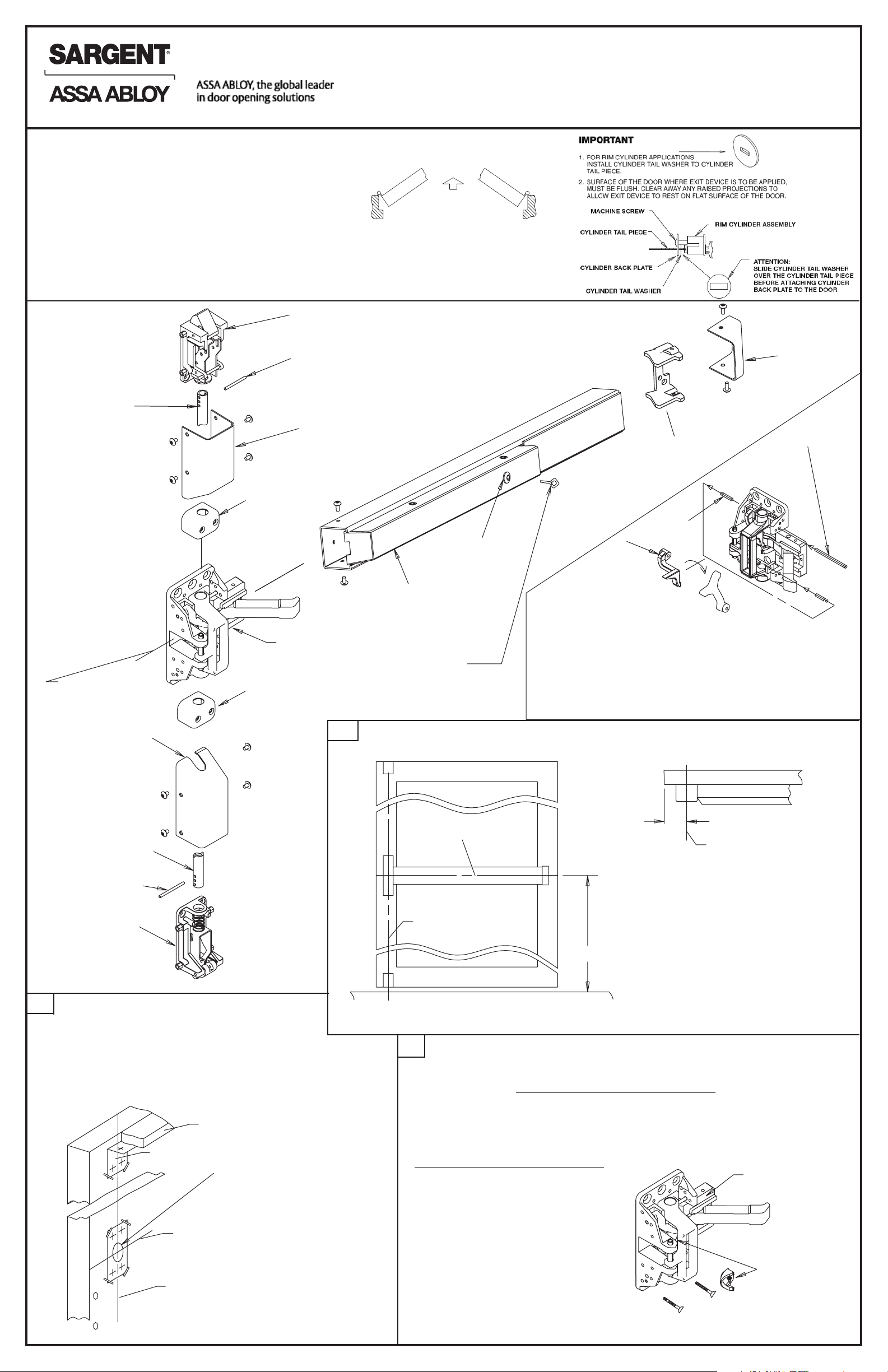
CAUTION: BEFORE STARTING
• DOOR SHOULD BE FITTED AND HUNG
• CHECK BOX LABEL FOR HAND AND SIZE OF EXIT DEVICE
AVAILABLE STOCK LENGTHS
LENGTH E 32" DOOR. CAN BE CUT TO FIT 24" DOOR.
LENGTH F 36" DOOR. CAN BE CUT TO FIT 30" DOOR.
LENGTH G 48" DOOR. CAN BE CUT TO FIT 36" DOOR.
Lift
lever
Lift
lever
pin
2-1/4" long pin
Top case
Rail assembly
Top rod
Guide
Guide
Bottom
rod
Adjustment
pin
Bottom
case
Vertical reference line
(C
L of chassis)
Vertical reference line
(C
L of chassis)
Horizontal reference line
(C
L of chassis and rail assembly)
Horizontal reference line
(C
L of chassis and rail assembly)
Horizontal reference line
(C
L of chassis and rail assembly)
Vertical reference line
(C
L of chassis)
US PATENT NO. 268003
CANADIAN PATENT NO. RD1981
ALL 3727 SERIES EXIT DEVICES
ARE HANDED AND REVERSIBLE. NORMALLY ASSEMBLED FOR
A LEFT HAND REVERSE BEVEL DOOR AT THE FACTORY.
TO CHANGE HAND OF 3727 EXIT DEVICE:
1. USE 2-1/4" PIN (SUPPLIED IN SCREW PACK) TO PUSH OUT
LIFT LEVER PIN.
2. REMOVE LIFT LEVER. INVERT AND REASSEMBLE WITH LIFT
LEVER PIN AS SHOWN.
THIS EXIT DEVICE IS HANDED
Door stop
Top case
template
TAPE TEMPLATES ON INSIDE OF DOOR ALONG
REFERENCE LINES WITH SUPPLIED TAPE
IF DOOR ALREADY HAS ANSI DOOR PREP (161 CUT-OUT) OR HAS
2-1/8" DIA. HOLE AT 2-3/4" BACKSET, POSITION TEMPLATE OVER EXISTING
HOLE AND SPOT AND DRILL HOLES
1.
DETERMINE DIMENSION “A”
- IF LOCK STILE IS APPROX. 4-1/2"
WIDE OR WIDER, DIM. A = 2-3/4"
- IF LOCK STILE IS LESS THAN 4-1/2"
WIDE, DIM. A = 1/2 OF THE VISIBLE
WIDTH OF THE LOCK STILE (WHEN
DOOR IS CLOSED AGAINST STOP)
FINISHED FLOOR Refer to template to locate
horizontal reference line
RIGHT HAND
REVERSE BEVEL
LEFT HAND
REVERSE BEVEL
OUT
Bottom
cover
Center chassis
assembly
Top cover
Adjustment pin
Lockdown
button
“Lockdown key”
To operate:
Depress pushrail; insert hex key
and turn
Mounting plate
End cap
Door
Dim “A”
2. PREPARE DOOR
3. APPLY HARDWARE
ANSI A156.2 series cross bore hole
when knob rim or lever handle trim
is used
FOR LEVER TRIM APPLICATIONS
SEE SEPARATE INSTRUCTION SHEET PACKED WITH TRIM
41”
INSTRUCTIONS FOR INSTALLING
3727 / NB3727 SERIES
VERTICAL ROD EXIT DEVICE
FOR ASSISTANCE, CONTACT SARGENT AT 800-727-5477 or www.sargentlock.com
Copyright © 2003, 2008, 2012, Sargent Manufacturing Company, an ASSA ABLOY Group company. All rights reserved.
Reproduction in whole or in part without the express written permission of Sargent Manufacturing Company is prohibited.
NOTE: FOR EXIT APPLICATIONS ONLY
REMOVE AND DISCARD CAM FROM
CENTER CHASSIS FOR FLUSH
MOUNTING. ATTACH CHASSIS WITH
FOUR (4) #10 WOOD OR MACHINE
SCREWS.
Cam
Center
chassis
cam
MARK VERTICAL AND HORIZONTAL
REFERENCE LINES ON DOOR
ATTACH COVER TO
CHASSIS WITH (4) #8 TRUSS
HEAD MACHINE SCREWS
• CHECK BOX LABEL.
DEPRESS ARM INTO RAIL OPENING AND SLIDE RAIL ONTO
CHASSIS. LEVEL RAIL AND FASTEN MOUNTING PLATE
A
Copyright © 2003, 2008, 2012, Sargent Manufacturing Company, an ASSA ABLOY Group company. All rights reserved.
Reproduction in whole or in part without the express written permission of Sargent Manufacturing Company is prohibited.
Main slide
Retractor
3727 INSTALL TOP & BOTTOM CASES NB 3727 INSTALL TOP CASE
Center chassis
assembly
Guide
Top cover
Top rod
Adjustment pin
Top case
4.
3727
1. MOUNT TOP STRIKE ACCORDING TO LOCATION
MARKED IN SECOND STEP. USE #10 STEEL
SCREWS PROVIDED
2. SCREW TOP ROD INTO MAIN SLIDE.
3. SLIDE GUIDE AND COVER ONTO TOP ROD
AND ASSEMBLE TO TOP CASE BY INSERTING
ADJUSTING PIN THRU RETRACTOR AND
MIDDLE HOLE IN ROD (SEE ILLUSTRATION AT
LEFT). ADJUST SO THAT TOP CASE MOUNTING
HOLES LINE UP WITH LOCATION MARKED IN
SECOND STEP.
4. MOUNT BOTTOM CASE IN SAME MANNER AS
TOP CASE (SEE ILLUSTRATION AT LEFT). REFER
TO ILLUSTRATIONS BELOW FOR MORTISE OR
SURFACE APPLIED STRIKE APPLICATIONS.
5. SECURE ROD GUIDES
NOTE: IF SHORTER RODS ARE REQUIRED,
CUT TO LENGTH AND DRILL Ø1/8"
HOLE THROUGH.
ATTACH RAIL END CAP TO
MOUNTING PLATE WITH (2)
COVER SCREWS
VERTICAL REFERENCE LINE
(C CHASSIS)
L
FOR DOORS WITH STILE,
RAIL MUST OVERLAP STILE
BY 1/2" MIN.
CUT OFF ON MARK
AND DEBURR
Attach rail assembly to the chassis with two
#8 Truss head machine screws
Level Mounting plate
2" MIN.
“X”
“Y”
Adjustment Pin
Bottom case
Bottom
cover
Guide
TOP STRIKE
3727 / NB3727
1/8" GAP REQUIRED
SHIM TOP STRIKE
WHEN NECESSARY
TO OBTAIN 1/8" GAP
Retractor
Guide
Top cover
Top rod
Adjustment pin
Top case
Main slide
NB 3727
1. MOUNT TOP STRIKE ACCORDING TO LOCATION
MARKED IN SECOND STEP. USE FOUR (4) #10
STEEL SCREWS AND MORTISE NUTS IN THE
FOUR CORNER MOUNTING HOLES
ILLUSTRATED IN THE TOP CASE.
2. SCREW TOP ROD INTO MAIN SLIDE
3. SLIDE ROD GUIDE AND COVER ONTO TOP ROD
AND ASSEMBLE TO TOP CASE BY INSERTING
ADJUSTING PIN THRU RETRACTOR AND MIDDLE
HOLE IN ROD (SEE ILLUSTRATION AT RIGHT).
ADJUST SO THAT TOP CASE MOUNTING HOLES
LINE UP WITH LOCATION MARKED IN SECOND
STEP.
NOTE: IF SHORTER RODS ARE REQUIRED, CUT
TO LENGTH AND DRILL .125 / 1/8" DIA
THROUGH HOLES
1/4"
MORTISE TYPE BOTTOM STRIKE
1/8"
SURFACE APPLIED BOTTOM STRIKE
DETERMINE CUT OFF DIMENSION “X” BY SUBTRACTING 2" FROM
DIMENSION “Y”
B
A7425F
Center chassis
assembly
APPLY COVERS
6.
INSTALL RAIL ASSEMBLY
RAIL CUTTING INSTRUCTIONS
5.
ATTACH COVERS TO TOP
AND BOTTOM CASES WITH
(4) COVER SCREWS EACH
PLACE MOUNTING PLATE TIGHT
AGAINST RAIL AND ATTACH IT
TO THE DOOR WITH#10 ROUND
HEAD SCREWS

This manual suits for next models

1

Other Sargent Door Opening System manuals

Sargent POWERGLIDE Series Instruction Manual

Sargent

Sargent POWERGLIDE Series Instruction Manual

Sargent ASSA ABLOY 8800 Series User manual

Sargent

Sargent ASSA ABLOY 8800 Series User manual

Sargent 1431 series User manual

Sargent

Sargent 1431 series User manual

Sargent 1130 Series User manual

Sargent

Sargent 1130 Series User manual

Sargent Fireguard 2900 Series User manual

Sargent

Sargent Fireguard 2900 Series User manual

Sargent 2600 Series Guide

Sargent

Sargent 2600 Series Guide

Sargent POWERGLIDE 281 User manual

Sargent

Sargent POWERGLIDE 281 User manual

Sargent 1431 series User manual

Sargent

Sargent 1431 series User manual

Sargent 3828 Series Instruction Manual

Sargent

Sargent 3828 Series Instruction Manual

Popular Door Opening System manuals by other brands

Stanley M-Force Operation and maintenance manual

Stanley

Stanley M-Force Operation and maintenance manual

Excel XL8000 Series Installation

Excel

Excel XL8000 Series Installation

Nabco GYRO TECH GT-1175 Wiring and Programming Manual

Nabco

Nabco GYRO TECH GT-1175 Wiring and Programming Manual

Dorma 8616 ARNP manual

Dorma

Dorma 8616 ARNP manual

FAAC 595 manual

FAAC

FAAC 595 manual

Nabco GT20 owner's manual

Nabco

Nabco GT20 owner's manual

Dorma EM installation instructions

Dorma

Dorma EM installation instructions

Dormakaba 8900 EMR installation instructions

Dormakaba

Dormakaba 8900 EMR installation instructions

Dorma 9800FL Series manual

Dorma

Dorma 9800FL Series manual

CDVI Digiway SR Easy start guide

CDVI

CDVI Digiway SR Easy start guide

Dormakaba G-SR EMR Series Fixing instructions

Dormakaba

Dormakaba G-SR EMR Series Fixing instructions

GEZE TS 4000 R installation instructions

GEZE

GEZE TS 4000 R installation instructions

CAME SIPARIO1 Assembly and installation manual

CAME

CAME SIPARIO1 Assembly and installation manual

Lamp AZ-AT230-HL Nstallation instructions

Lamp

Lamp AZ-AT230-HL Nstallation instructions

Johnson Controls MC-302E PG+ installation guide

Johnson Controls

Johnson Controls MC-302E PG+ installation guide

Cavity Sliders SofStop installation instructions

Cavity Sliders

Cavity Sliders SofStop installation instructions

DEUTSCHTEC SLH Series installation manual

DEUTSCHTEC

DEUTSCHTEC SLH Series installation manual

Assa Abloy SARGENT 1130 Series installation instructions

Assa Abloy

Assa Abloy SARGENT 1130 Series installation instructions

manuals.online logo
manuals.online logoBrands
  • About & Mission
  • Contact us
  • Privacy Policy
  • Terms and Conditions

Copyright 2025 Manuals.Online. All Rights Reserved.