SAS 1SF User manual

SAS 1SF - Twin Screw Feeder Assy & Control - APRIL 2020
SAS 1SF
–
Twin Screw Feeder
INSTRUCTION MANUAL
Unit 3 Hawksworth, Didcot, OX11 7HR, England, UK
Tel: 00 44 1865 747 634 Fax: 00 44 8701 602 755
info@spiceapplications.com www.spiceapplications.com

1
SAS 1SF - Twin Screw Feeder Assy & Control - APRIL 2020
INDEX
DESCRIPTION OF INFORMATION PAGE NUMBERS
WARNINGS OVERVIEW………………………………………………………. 2-4
EC DECLARATION OF CONFORMITY FOR MACHINERY………………. 5
PRODUCT INTRODUCTION…………………………………………………. 6-7
INSTALLATION…………………………………………………………………. 8-10
OPERATING PRINCIPLE……………………………………………………… 11-12
START UP…………………………………………………………………….…. 13
CLEANING………………………………………………………………………. 14-16
SERVICING……………………………………………………………………… 17-21
KEY COMPONENT REPLACEMENT………………………………………… 22-24
TROUBLESHOOTING…………………………………………………………. 25-26
DECOMMISSIONING…………………………………………………………... 27
SPARE PARTS…………………………………………………………………. 28-30
DIMENSIONS…………………………………………………………………… 31-32
TECHNICAL SPECIFICATIONS……………………………………………… 33-34
WARRANTY……………………………………………………………………. 35
To obtain the best performance and reliability from this equipment it is
strongly recommended to read the instruction manual thoroughly
before attempting to use the equipment.

2
SAS 1SF - Twin Screw Feeder Assy & Control - APRIL 2020
WARNINGS OVERVIEW
SAFETY GUIDELINES
The person in charge of the manufacturing work area should ensure that
personnel are properly trained in the use of this equipment. The safety rules
which follow should be fully understood and applied at all times.
For more information, consult the local safety rules. In addition, the following
precautions must be observed.
WARNING! Failure to observe the safety precautions contained within this manual
could result in operational difficulties of the equipment and potential to create
unsafe conditions.
The removing of the protective equipment and/ or modifying the machine without
previous authorization by the manufacturer is strictly forbidden.
•Use only spare parts, accessories or materials that are original or instead
item and materials provided by the manufacturer.
•Do not put or approach the hands and/or other objects near the movement
blocks in order to avoid crushing risks.
•The installation and even the partial use of the equipment are forbidden to the
unauthorized operators.
•It is compulsory the grounding of the metallic box.
•Any use of the equipment different from the intended one is strictly forbidden.
•Read carefully the warning and danger plates on the equipment.
•It is forbidden to remove the warning and danger plates on the equipment.
•It is forbidden to start up the equipment before the installation is declared
compliant to the directive 2004/108/EC.
•The installer has to provide the suitable devices for the products that are
dangerous and harmful by contact and/or by inhalation, flammable, explosive
and dangerous from a bacterial and/or viral point of view. Concerning this
part the installer has to set up all the protections in order to avoid damages to
things or people if breakings with consequent fall of pieces from the
equipment occurs.
•Do not start the machine without having the complete knowledge about the
functioning.
•Do not clean, make maintenance, substitute or adjust machine components if
the voltage in on.
•The people responsible for the use of the machine have to check and provide
the correct use of the equipment according to the requests, the regulations,
the laws and the European community Standards.

3
SAS 1SF - Twin Screw Feeder Assy & Control - APRIL 2020
WARNINGS OVERVIEW
•Notes for screw feeders assigned at the transport of food, pharmaceutical
and zoo-technical products:
oPeriodically clean the screw feeders; the cleaning frequency depends
on the type of product processed and on the nature of the system. It
must be fixed by the people responsible for the use of the machine.
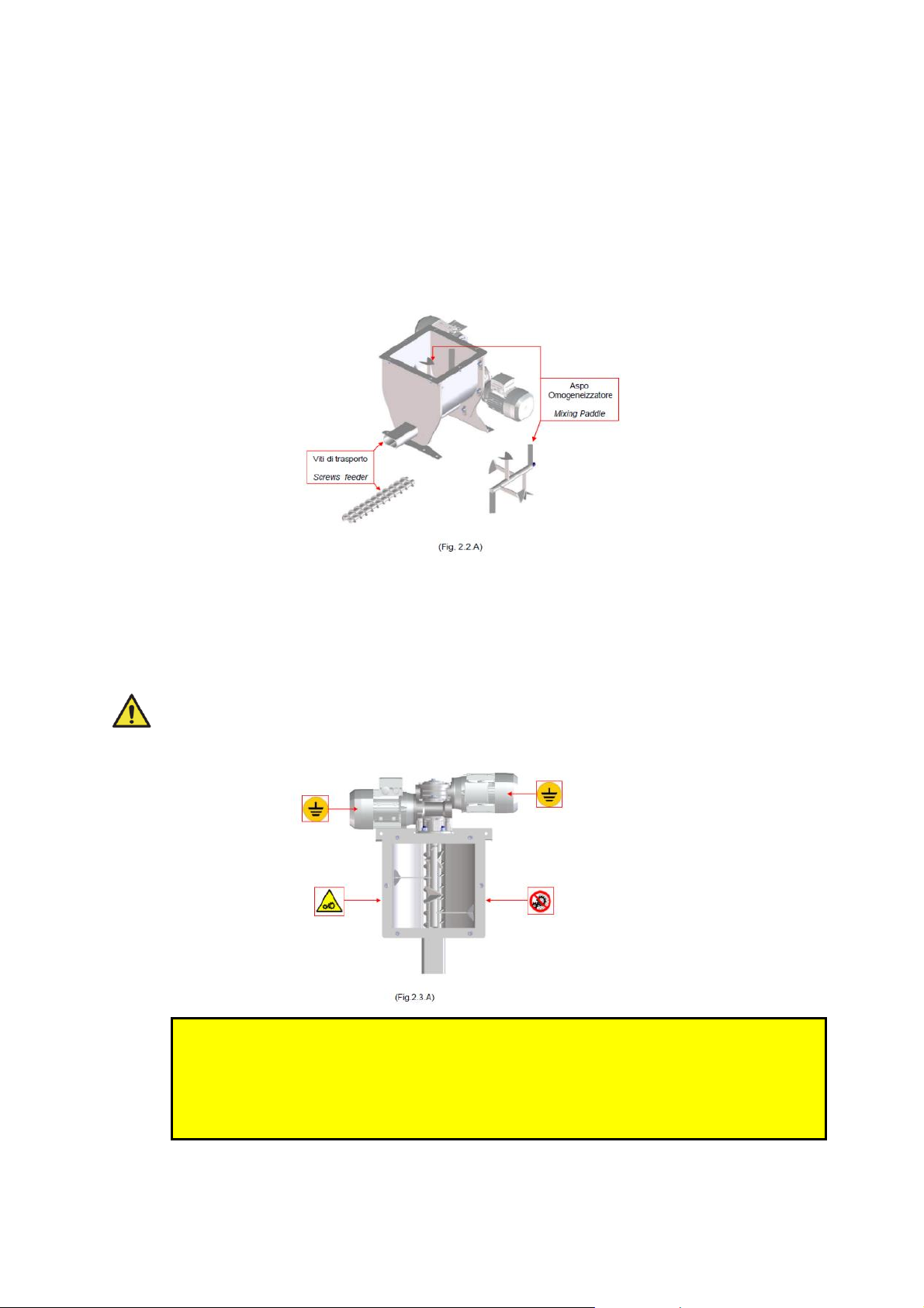
oGreat attention must be paid to the cleaning of the dispenser body, the
dispensing screw, the protections, etc.
oIf it is necessary to clean with other products that are difficult or
impossible to list because of their nature, it is necessary that the
customer previously informs our technical office.
IT IS STRICTLY FORBIDDEN
the use of the equipment if some anomalies occurs
(excessive noise, vibrations, etc).
WARNING:
The failure of the safety standards observance and advices for corrected
machine maintenance or the possible tampering of safety standard relieves
Spice Application Systems Ltd and their suppliers in case of responsibility of
fire, damage or plant/line/machine malfunctioning.
INAPPROPRIATE USE
An inappropriate use of the machine may have serious risks for people and/or
the environment as well as causing damages to the equipment itself.
The equipment must be used only for the purposes specifically expected by the
manufacturer:
•Do not use the equipment if it’s not correctly installed, do not start it up if
the engine group is not mechanically fixed to the rest of the machine.
•Do not use the equipment if the rotating part are not intact or perfectly
cleaned. In this case the dosing power and the capacity are not
guaranteed.
•Do not use the screw feeders with a screw exceeding the length of the
exhaust pipe.
•Do not use the equipment as a supporting point even if it is not working.
There is the danger to fall or to damage the machine itself.
•Do not work on the electric engine or on any other electric component if
the power supply is on, in order to avoid electrocution.
•Do not wash the machine with a water jet. The electric motor is not
shielded from dust and water.
•Do not use products that do not have a clear composition, chemically
aggressive, flammable or dangerous for the machine or the operator
•Do not operate the machine outside, exposed to weather and sudden
changes of temperature.

4
SAS 1SF - Twin Screw Feeder Assy & Control - APRIL 2020
WARNINGS OVERVIEW
IDENTIFICATION OF HAZARDOUS MOVING PARTS
On the machine are present mobile elements potentially harmful.
These elements are not reachable during functioning because of their position,
because they are behind grids or other system devices.
Pay attention to these elements during cleaning and maintenance
POSITIONING OF SAFETY SIGNS
During the normal cycle, dangerous mobile elements are not reachable.
Operators are trained on possible critical situations and safety sign are
positioned on the machine.
WARNING:
In case that one or more signs are damaged it is necessary to substitute them.
ALL personnel who are associated with the coating operation should
read and fully understand this manual. It is especially important that
the operators and maintenance team of the electrostatic equipment
and their supervisory personnel understand the requirements for safe
and proper usage of the electrostatic process.

5
SAS 1SF - Twin Screw Feeder Assy & Control - APRIL 2020
EC DECLARATION OF
CONFORMITY FOR MACHINERY

6
SAS 1SF - Twin Screw Feeder Assy & Control - APRIL 2020
PRODUCT INTRODUCTION
Twin Screw Feeder Type: SAS 1SF
The SAS 1SF twin screw feeders are designed for the dosing of powder materials.
Equipped with a double extracting screw, they provide a homogeneous material flow, high
precision and dosing control together with integrated material agitation provided by an
internal paddle.
SAS Part Number –SAS 1SF-BBL-CC
Description
Part Number Reference
BB
Product Hopper –20 Litre
20L
Product Hopper –50 Litre
50L
CC
Gearbox Ratio (main drive) –14:1
14
Gearbox Ratio (main drive) –21:1
21
Gearbox Ratio (main drive) –60:1
60
Gearbox Ratio (main drive) –100:1
100
Example Part Number : SAS 1SF-20L-60
Twin Screw Feeder c/w 20L hopper & 60:1 Gearbox

7
SAS 1SF - Twin Screw Feeder Assy & Control - APRIL 2020
PRODUCT INTRODUCTION
TYPICAL POWDER OUTPUT RANGE
Please Note
The above table is for reference only and provides an approximate indication of Powder
Throughputs. Please contact SAS directly with details of your powder materials.
Fig 1
SAS 1SF –Twin Screw Feeder Assy overview
Pos.
Description
Assembly
Number
Manual Reference
A
Twin Screw Feeder Main Body
SF 200-138-XXX
See page 28 –Fig 8
B
Product Hopper Size (2 sizes)
SF 100-1XX
See page 30 - Fig 10
C
Motor/Gearbox Ratio (4 sizes)
---
See Table above on page 7
D
Twin Screw Set (3 sizes)
SF 100-14X
See page 29 - Fig 9
E
Invertor Control –E3
100-177
See separate Invertor Manual
F
Mounting Stand - Mobile
SF 200-292
See page 30 –Fig 11
Ratio Screw Sets 2 4 8 10 12 14 16 20 23 28 40 44 48 70 92 140 172 225 280
EX Single Pitch
EX Double Pitch
MC
EX Single Pitch
EX Double Pitch
MC
EX Single Pitch
EX Double Pitch
MC
EX Single Pitch
EX Double Pitch
MC
21:1
14:1
SAS 1SF
Twin Screw Feeder
100:1
Litres/Hour
60:1
A
B
E
C
D
F

8
SAS 1SF - Twin Screw Feeder Assy & Control - APRIL 2020
INSTALLATION
During the installation there are combined actions of several operators, thus is
necessary work with great caution.
Verify the integrity of the machine, particularly of the fan covers over the electric motors
that can be damaged during transport.
If the fan covers are dented blocking the fan rotation, restore or replace them before
commissioning the machine.
When the screw feeder is provided without vertical unload and endless screw, with
length of the screw exceeding the one of the exhaust pipe because of a customer
request for installation needs, the customer is in charge of performing a risk analysis
and of mounting proper protections and/or repairs.
The operations performing the installation must have a technical grounding and proper
knowledge to operate with adequate expertise.
The user must have an installation area that satisfies the current regulations on health
and safety on production environments.
Set up an area where install the machine verifying that the floor is flattened and without
obstacles.
Make room around the machine sufficiently to permit safety and ergonomics to the
operators and to the fitters. Safety distances from other machines or production areas
must be observed according to the current regulations.
The installation and working area must be correctly lit up, defined and signalled. It must
respect the law parameters concerning working areas.
The working area must be forbidden to personnel not involved in the machine
operation. If this is not possible, barriers or similar means not hindering the production
must be installed
WARNING: The set-up of the machine is usually performed by the manufacturer
who knows the right methods to do it. In case that the set up cannot be
performed by the manufacturer, the customer has to ask the manufacturer all the
information in order to perform it correctly by himself.

9
SAS 1SF - Twin Screw Feeder Assy & Control - APRIL 2020
INSTALLATION
ACCIDENT PREVENTION WARNINGS
•Wear the suitable prevention equipment for the operation that has to be carried
on. The clothing must be tight fitting to the body. Avoid wearing ties, necklaces or
belts that could go in the movement parts.
•Do not remove the safety devices or the accident prevention protections.
•Do not turn on or misadjust the control points or the tools on the equipment
without authorization or without knowing the functioning.
•Every technical change that can have repercussion on the functioning or the
safety of the equipment must be performed only by technicians of the
manufacturer or by technicians authorized by him.
WARNING: A good installation gives more steadiness to the machine and avoids
vibrations and noise.
WARNING: Spice Application Systems Ltd declines every responsibility
coming from the not fulfilment of the above mentioned instructions.
TRANSPORTATION AND RECEIPT OF GOODS
•Check that during the transport any damage to the structure or internal parts of
the equipment has not occurred.
•Any damage must be immediately signalled on the packing note. The driver must
accept the complaint and leave one copy for you.
•For any contact with our technical assistance please always quote the part
number and the manufacturing year.
•Damages verified after unpacking must be notified within 7 working days.
ELECTRICAL CONNECTIONS
(Please refer to separate Invertor Manual)
The electric connection of the equipment must be performed only by qualified
personnel, according to the current directives.
Before connecting the power, please check with a voltmeter that the phase of the
line correspond to the one of the equipment. The power needed is written on the
identification plate and on the engine plate.
•Check the presence and the functioning of the grounding system in power
supply.
•Check that the main switch at the beginning of the equipment power line is in
“0”position.
•Check the rotation direction of the engine.
•Always pay attention to the safety requirements.

10
SAS 1SF - Twin Screw Feeder Assy & Control - APRIL 2020
INSTALLATION
Typical Installation with SAS 1DV system & SAS Coating Drum
Fig 2

11
SAS 1SF - Twin Screw Feeder Assy & Control - APRIL 2020
OPERATING PRINCIPLE
TWIN SCREW FEEDER
The D series screw feeders are equipped with a double extracting screw, they guarantee
a homogeneous material flow, high precision and dosing regularity thanks also to the
screws that are machine made for a perfect coupling.
The D series twin screw feeders are designed for the dosing of powdered material and
synthetic fibres. They are available both on volumetric and gravimetric version with an
electronic loading cell weighting system that guarantees high precision and reliability.
They are used in their different configurations in all industrial fields, from concrete to
chemistry, from food to pharmaceutical industry.
The different configurations make them suitable for the use of materials that have very
different granulometry and fluency.
They are available also in configuration for ATEX areas.
A screw feeder makes the function to unload a theoretically constant material quantity on
each turn. This behaviour allows to make a specific load both on the granulometric and
volumetric version. It is expressed in dm³/h and the value is determined by the following
factors:
oDosing screw rotating speed.
oDosing screw pitch and diameter length.
oUsed product specific weight.
The machine is givenwith dosage members suitable to guarantee the required capacities
in connection with the material characteristic, as written in the specifications transmitted
by the manufacturer.
The machine dimensions are based on tables obtained by the manufacturer expertise.
For this reason, potential differences of behaviour due to the specific material to be
processed and due to the specific environment cannot be discovered before the test.
In any case, if it is necessary to change some part of the system to change the capacity
or to process different materials from the ones foreseen, consult the manufacturer.
The D-series twin screw feeder is provided completely assembled in one piece with
different dimensions composed by:
oHopper
o2 three-phase induction motors; (Fig.4.A)
o2 worm reduction gearboxes; (Fig.4.B)
oA screw feeder body made of stainless steel for containing the material; (Fig.4.B)
oA mixing paddle chosen between different models to mix the material inside the
screw feeder body (Fig.4.B)
oTwo endless screws for the transport of the material (Fig.4.B)

12
SAS 1SF - Twin Screw Feeder Assy & Control - APRIL 2020
OPERATING PRINCIPLE

13
SAS 1SF - Twin Screw Feeder Assy & Control - APRIL 2020
START UP
TWIN SCREW FEEDER
•Check that during the transport any damage to the structure or internal parts of
the equipment has not occurred.
•Check that the power supplied is compliant to the machine one.
•Check the presence and integrity of the danger and warning signs.
•Check if water or external substances have entered the screw conveyor. If so
take away the cover, clean the equipment and reassemble.
•Strictly avoid every flexion of the screw feeder, controlling the perfect alignment
between inlet and outlet ports, or the endless screw can be damaged.
•Check the rotation direction of the screw. If it is not correct invert the connection
on the engine.
•Check the right level of the oil in the motor gear.
•Check that the warning signs on the machine is in good conditions.
•Check the correct machine fastening and its stability.
•Check the correct functioning of the auxiliary equipment.
•Check the integrity and correct functioning of all guards and protective devices.
The transport or the installation might damage or misadjust them.
•Check the working temperature of the different components: they do not have to
overheat.
•The first start up test must be done with the empty screw conveyor for about
thirty minutes, if any noise, vibrations or other things that may suggest a bad
functioning don’t occur then the loading with other material can be done.
•After the first 12 hours of the working cycle check the tightness of the bolts.
It is absolutely forbidden to work inside the feeder while it is functioning.
It is absolutely forbidden to open the inlet and outlet ports and the covers with the
electrical power On.
WARNING: It is absolutely forbidden to take off the safety guards during the
equipment functioning.
Remove the safety guards only after switching off the power supply.
This operation is allowed only to technical qualified personnel.
WARNING: it is compulsory to isolate any energy supply of the line anytime the
maintenance and adjusting operations are performed.
Before starting the equipment, by turning the main switch on the ON position, it is
necessary to:
Nobody is nearby the equipment.
•The safety devices are present and functioning.
•The safety guards are completely closed.

14
SAS 1SF - Twin Screw Feeder Assy & Control - APRIL 2020
CLEANING METHOD
CLEANING OF THE SCREW FEEDER
With the machine turned off and disconnected from the power line, use a dry and clean
cloth to clean the exterior of the machine, if necessary soaked with a suitable non-toxic
and non-abrasive detergent.
Do not wash the machine with a high pressure water jet around the
electric motor.
For the body cleaning, once it has been disassembled, it is possible to use water
because no electric components exposed are present and the materials allow this
method.
The modular assembling of the machine permits an easy disassembling, easing the
cleaning and sanitizing procedures during a change of processed product.
Particularly, the motor group has no connection with the gears present on the screw
feeder body.
Disassemble the machine following the operations listed below:
1. Unwire the machine from the power line
2. Release the hopper from the screw feeder body loosening the nuts positioned
under the flange and rotating toward the outside the fixing hooks
3. Take the frontal of the screw feeder body off after loosening the locks (knobs or
nuts) using the suitable tools and, if they are present, loosening the grub screws
of the guide bearing present in the mixing paddle (Fig. 7.2.1.A).
4. Loosen the break-bridge agitating paddle always clockwise and take it off from
the screw feeder body (Fig. 7.2.1.A)
5. Loosen the endless screws always clockwise and take them off from the screw
feeder body (Fig. 7.2.1.A).

15
SAS 1SF - Twin Screw Feeder Assy & Control - APRIL 2020
CLEANING METHOD
6. Loosen the locks (knobs or nuts) from the back plate of the motors using proper
tools (Fig. 7.2.1.B).
7. Take the screw feeder body off from the motors and from the frontal holding (Fig.
7.2.1.B)
To re-assemble the components follows the procedure listed above in reverse order. Not
following this procedure can cause problems and void the warranty on the machine and on
the components.
WARNING
Never switch ON the electric power supply unit during the washing and cleaning
operation.
All metallic parts located within and around the applicator head must be correctly
connected to the ground. Any floor coating must be electrically conductive and
grounded.
Do not stand upon wooden pallets or a non-grounded structure while cleaning.
DO NOT USE HIGH PRESSURE CLEANING SYSTEMS ON THE APPLICATION
EQUIPMENT AND CONTROLS.

16
SAS 1SF - Twin Screw Feeder Assy & Control - APRIL 2020
CLEANING PROCEDURE
•The ON/OFF switches on the power supply and to the equipment must be OFF
position before starting cleaning operation.
•Wait for 10 seconds before entering the spray area.
•Wash thoroughly and dry completely with low pressure compressed air at 2 bar
(29psi)
•Wipe dry the equipment, plus all hoses and cables carefully and thoroughly,
before commencing production.
THIS IS VERY IMPORTANT.
IF NOT DRY IT CAN LEAD TO MATERIAL BUILD UP ON THE EQUIPMENT.
Before switching the electrostatic back ON, please check:
1. Check that the equipment plus all hoses and cables are completely dry.
2. Check that all equipment within the application area is correctly installed and
positioned.

17
SAS 1SF - Twin Screw Feeder Assy & Control - APRIL 2020
SERVICING OVERVIEW
WARNING
The personnel involved in the electrostatic coating system servicing must be
trained and qualified. If you face any troubles which cannot be repaired after
consulting the Troubleshooting and Maintenance guides, do not try to start the
equipment. Consult your local authorised SAS distributor or SAS directly for
assistance.
•Maintenance procedures have to be well understood before the machine start up
in order to avoid accidents.
•Unauthorized personnel is not allowed in the working area.
•People who are not trained for the use or the maintenance are not allowed to use
the machine.
•Keep the working area, clean, dry and clear from materials.
•Do not perform any operation while the machine is working.
•Before performing any operation on the machine, put the sign “machine in
maintenance” on the control panel.
•During maintenance or repairing operations the unauthorized personnel must
keep out of the area.
•The deactivation of the protection and safety devices must be performed only by
authorized operators and only for maintenance reasons. The operator will
guarantee the safety of the personnel and will avoid any damage to the
equipment as well as turning on again the safety and protection devices after the
maintenance has been completed.
•The maintenance operations need a suitable equipped workshop.
•The spare parts must always correspond to the technical requests of the
manufacturer, this can be guaranteed by using original spare parts.
•It is forbidden to turn on or misadjust the checking parts or tools on the machine
without authorization or without knowing the exact functioning.
•Keep all the components in good conditions and installed in the right way.
•Immediately repair any breakdown/failure.
•Repair and substitute all the damaged or torn components.
•Take note of any anomaly and report them to the maintenance supervisor.
•Use working tools with double insulation and low safety voltage (SELV) or
external power (battery).
•Do not impede the transit with power cables.
•Do not touch warm or sharp parts on the machine.
•Put one fire extinguisher near the working area.
•The maintenance technicians who work on the electric panel must have a proper
training in order to have the acknowledgement of expert person (PES) or
informed person (PAV) according to law CEI EN 50110 and CEI 11-27. The law
CEI 11-27 is about the training of technicians who work on electric panel with
voltage not above 1000 volt in AC and 1500 in DC and it identifies the involved
people and their training.
•The electric maintenance cannot be performed by untrained personnel.

18
SAS 1SF - Twin Screw Feeder Assy & Control - APRIL 2020
SERVICING OVERVIEW
•Before beginning the maintenance operations clean the working area and take
away all the objects that can be dangerous.
•Light adequately the working area with portable safety lamps.
•The maintenance technicians have to be adequately trained and well skilled
about the maintenance process.
•The machine user is responsible for the training level of the maintenance
technicians according to the requirements of this manual.
•Wear the suitable protection devices for the operations that have to be
performed. The clothes must be tight to the body and resistant to the cleaning
products. Avoid wearing ties, necklaces, belts or anything else that can entangle
into the moving parts of the machine.
•Operators under alcohol or drugs effects cannot be authorized to use the
machine or to perform any maintenance operation.
•Every maintenance or repairing operation must be carried out by trained
operators or personnel that have the necessary physical and intellective
requirements.
•Maintenance and repairing operations must be carried out under the supervision
of only one person.
•At the end of the maintenance/repairing operations the machine must be started
up only after the OK of the supervisor who has to check that:
othe work has been performed correctly.
othe machine works perfectly.
othe safety systems are working.
onobody is working on the machine.
•The manufacturer is not responsible if the maintenance is not performed
following the directions on this manual. The manufacturer is not responsible for
any damage to people/things that come from a wrong or incomplete
maintenance.
•If the user requires it the manufacturer can provide qualified personnel for the
machine maintenance according to the current conditions.
•Before starting the machine, make sure that there are not any external things
(keys, screw, screwdrivers etc.) on the machine and that the adjusted or
replaced parts are firmly fixed.
•Check that on the floor there is no oil, grease or anything else that can make
operators fall or slip in the working area.
•If there is more than one operator working on the maintenance ,it is necessary to
warn them all before turning on the machine.
WARNING: Do not move by hands the mechanic parts of the machine. If the
Power is on, there can be dangerous movements for the operator safety.

19
SAS 1SF - Twin Screw Feeder Assy & Control - APRIL 2020
SERVICING OVERVIEW
It is absolutely forbidden to work inside the feeder while it is functioning.
It is absolutely forbidden to open the inlet and outlet ports and the covers with the
general power switch of the machine in “I” closed position.
WARNING: It is absolutely forbidden to take off the safety guards during the
equipment functioning.
Remove the safety guards only after switching off the power supply.
This operation is allowed only to technical qualified personnel.
WARNING: it is compulsory to isolate any energy supply of the line anytime the
maintenance and adjusting operations are performed.
It is absolutely forbidden to work inside the feeder while it is functioning.
It is absolutely forbidden to open the inlet and outlet ports and the covers with the
electrical power On.
WARNING: It is absolutely forbidden to take off the safety guards during the
equipment functioning.
Remove the safety guards only after switching off the power supply.
This operation is allowed only to technical qualified personnel.
WARNING: it is compulsory to isolate any energy supply of the line anytime the
maintenance and adjusting operations are performed.
Before starting the equipment, by turning the main switch on the ON position, it is
necessary to:
Nobody is nearby the equipment.
•The safety devices are present and functioning.
•The safety guards are completely closed.
Every operation has its own potential risks and dangers. Before starting any operation
carefully read the manual.
The above mentioned maintenance operations have to be performed by qualified
personnel.
To assure a perfect functioning of the machine it is necessary to perform a
general check every 24 hours.
Table of contents
Other SAS Industrial Equipment manuals