manuals.online logo
Brands
  1. Home
  2. •
  3. Brands
  4. •
  5. SMC Networks
  6. •
  7. Industrial Equipment
  8. •
  9. SMC Networks CKZ3N Series User manual

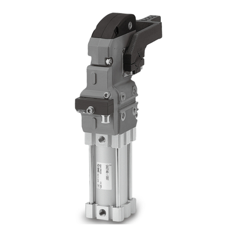
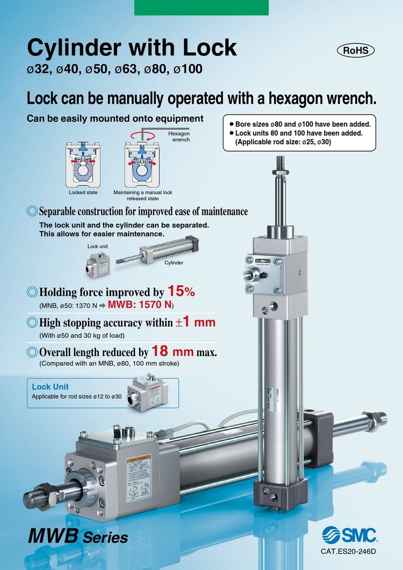
SMC Networks CKZ3N Series User manual

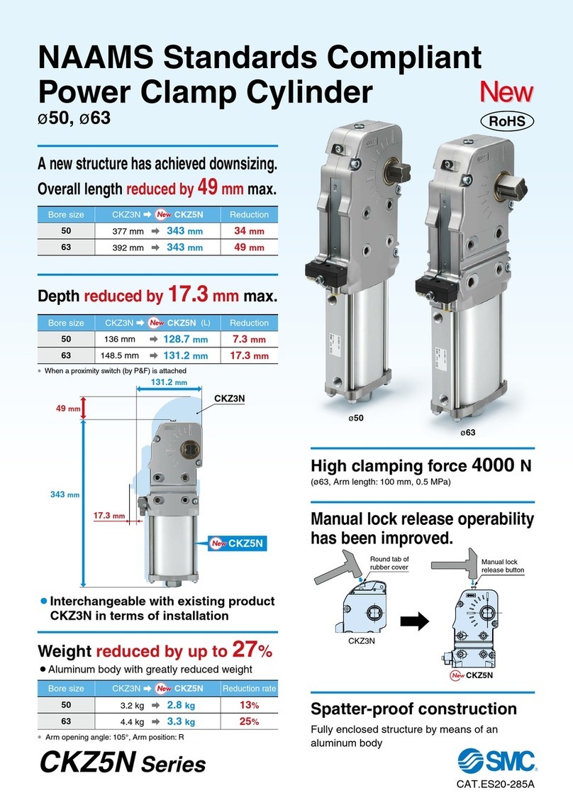
Aluminum body reduces
weight by up to 39%
Series CKZ3N
North American type
(Complies to standard.)
Series CKZ3T
European type
Weight reduced
by up to
39%7.16kg
CKZ3N63-135LT
4.36kg
New
Unclamping angle 15° as standard
15° angle shortens clamping time and improves cycle time.
CKZ2N63-135LT
Conventional model
Power Clamp Cylinder
ø50, ø63
CAT.ES20-202A
Series CKZ3
New
New
Series CKZ3N ø50, ø63
Cover: Rubber
Equivalent to UL94 standard V0:
Flame resistant
Cover: Metal
Open/close type
metal cover
Piston
Rounded cover design reduces
weld spatter accumulation.
Metal cover as standard option
• Suitable for arc welding lines
• Protects the cylinder from
unexpected external impact.
Without switch can also
be selected as standard.
Proximity cassette installation
and removal easily accomplished
by unfastening a single bolt.
Simple arm opening angle changes.
Oval shaped piston makes
space saving possible.
Cylinder disassembly is not necessary. The arm opening
angle can be changed by replacing the stopper bolt.
Stopper bolt
North American type
Power Clamp Cylinder
New
New
New
New
New
Aluminum clamping
body adopted
Product weight reduced by up to
39%
Unclamping
Unclamping angle 15° as standard
Rc port thread as standard
Series Clamp body
Bore size Made to Order specifications
Iron
Aluminum


50

63
—
80 Cylinder port
G,NPT,Rc
G,NPT
Unclamped
opening angle
15° to 135°
30° to 135°
Proximity
switch
• TURCK
• P&F
Metal cover
Standard

Front
mounting
Standard

Without
switch
Standard

Unclamped
opening angle 15°
Standard
CKZ3N
CKZ2N
NewNew
50–135°
(Arm position:R/L)
63–135°
(Arm position:R/L)
3.17kg
4.36kg
5.06kg
7.16kg
37%
39%
CKZ2N
Reduction
rate
CKZ3N
New
Manual toggle
release point
Conventional
model
Complies to NAAMS (North American Automotive Metric Standard).
75 arm variations available.
Spatter proof construction
Bore
size
(mm)
Arm
opening
angle
–
Switch cassette
Hexagon socket head cover cap screw
Features 1
Without switch can also
be selected as standard.
Series CKZ3T ø50, ø63
European Type
Power Clamp Cylinder
New
New
New
Oval shaped piston makes
space saving possible.
Series Clamp
body
Bore size Made to Order specifications
Aluminum
Iron
Aluminum

—
—

—

—

—  —
40 50 63 80
Cylinder
port
G,NPT,Rc
G,NPT
Unclamped
opening angle
15° to 135°
30° to 135°
Proximity
switch
Small bore size (ø25)
clamp cylinder
—
With angle
adjustment
—
With manually
operated handle
—
With pneumatic
sensor
—
Metal
cover
Standard
   
Unclamped
opening angle 15°
Standard

Without
switch
Standard
CKZ3T
CKZT
NewNew
• TURCK
• P&F
New
50–135°
63–135°
3.14kg
4.34kg
5.06kg
7.16kg
37%
39%
CKZ3T CKZT
New
12 arm variations available for each size.
Spatter proof construction
Cover: Rubber
Equivalent to UL94 standard V0:
Flame resistant
Rounded cover design reduces
weld spatter accumulation.
Manual toggle
release point
Switch cassette
Hexagon socket head cover cap screw
Proximity cassette installation
and removal easily accomplished
by unfastening a single bolt.
Stopper bolt
Conventional
model
Piston
Simple arm opening angle changes.
Cylinder disassembly is not necessary. The arm opening
angle can be changed by replacing the stopper bolt.
Bore
size
(mm)
Arm
opening
angle
–
Cover: Metal
Open/close type metal cover
New
Rc port thread as standard
Metal cover as standard option
• Suitable for arc welding lines
• Protects the cylinder from
unexpected external impact.
Unclamping
Unclamping angle 15° as standard
Aluminum clamping
body adopted
Product weight reduced by up to
39%
Reduction
rate
Model Selection
CKZ3N
North American Type
Made to Order
European Type
CKZ3T
Features 2
Series CKZ3T Arm
Manual release
Either rubber cover (equivalent to V0 of UL94)
or metal cover can be selected.
Toggle link mechanism
Maintains secure and powerful support.
Proximity switch
Both TURCK and P&F switches are available.
Without switch can also be selected.
Arm
Series CKZ3N
Bumper
Reduces the effects of impact
from unclamping the cylinder.
Software
CATIA
UNIGRAPHICS
FIDES
AUTO CAD
SOLID WORKS
3D CAD Series Variations
Series
Bore size (mm)
Arm opening angle
Switch
Port thread type
ø63 Equivalentø50 Equivalent
15°, 30°, 45°, 60°, 75°
90°, 105°, 120°, 135°
TURCK/P&F
NPT/G/Rc
CKZ3N/CKZ3T
Series CKZ3N
Series CKZ3T
Power Clamp Cylinder
∗For additional formats, please log on to
the SMC web site www.smcusa.com
and click on the E-Tech icon.
Front matter 1
+0.5°
0
Figure 1
Clamping
cylinder port
Unclamping
cylinder port
Cylinder
Clamp arm
Shim
Workpiece
receptacle
side block
Clamping
block
Shim
Clamping
cylinder port
Unclamping
cylinder port
Cylinder Clamp arm
Shim
Workpiece
receptacle
side block
Clamping
block
Shim
1Common precautions for each size
1) Use air filtered through a 5-µm-element filter.
2) Before piping is connected to the power clamp cylinder it should be thoroughly flushed with air.
3) Only use the clamp arm in our catalog. Do not weld an arm to the cylinder.
4) Always use a speed controller, and set it so that it takes at least
1 second from unclamped to clamped, and at least 1 second
from clamped to unclamped.
5) This product is designed to be used after being adjusted using a
shim. For this reason, it is set to between 0° to +0.5° at the
clamping end as shown in Fig. 1.
2Power clamp cylinder mounting
 When clamping by using clamping force only
Example)
Series CKZ3N Series CKZ3T
 Mounting process
Workpiece setting Air supply Operate to the
end of clamp
Shim adjustment
B
A
Install a block
at clamp side
Shim adjustment
C
Block contact adjustment
(clamp side)
 Procedure
A) Place the workpiece, supply air at clamp side without installing clamping block, operate the clamp arm to the end of clamp.
B) Under the above conditions, adjust shim so that the space between the workpiece and the clamping block is about 0 mm.
Theoretically there is no clamping force for holding a workpiece under this condition.
C) In order to generate clamping force from the state described in step B, insert additional shim. The thickness of the shim differs
depending on the arm length and pressure, so please refer to the graph on front matter 3 as a guide. About 10% error may
occur due to the difference in tolerance of the clamp cylinder body.
Model Selection
CKZ3N
North American Type
Made to Order
European Type
CKZ3T
Front matter 2
Series CKZ3
Model Selection 1
Arm length L
AArm length L
A
Arm length L: 150 mm
0
500
1000
1500
2000
2500
3000
0 0.5 1 1.5 2 2.5 3 3.5 4 4.5 5 5.5 6 6.5 7
Shim thickness (mm) Shim thickness
(mm)
Clamping force (N)
0.5 MPa
0.3 MPa
0.7 MPa
0.5 MPa
0.3 MPa
0.7 MPa
Recommended
shim thickness
Recommended
shim thickness
0.7 MPa
0.5 MPa
0.3 MPa
Peak clamping
force position
Arm length L: 200 mm
0
500
1000
1500
2000
2500
3000
0 0.5 1 1.5 2 2.5 3 3.5 4 4.5 5 5.5 6 6.5 7
Clamping force (N)
0.7 MPa
0.5 MPa
0.3 MPa
Peak clamping
force position
2Power clamp cylinder mounting
 Relation between shim thickness and clamping force
Note) When a shim that exceeds the clamping force peak plotted on the graph is inserted, the self-locking mechanism doesn’t work.
Insert a shim with appropriate thickness.
∗Arm length “L” indicates the distance between the clamp arm shaft and the clamping position.
For distance “A” between knock positioning pinhole and clamp arm shaft, refer to the Table 1.
CKZ3T50
CKZ3T63
10
10
AModel
Table 1
CKZ3N50
CKZ3N63
5
10
AModel
Table 1
Series CKZ3N Series CKZ3T
ø50 ø63
Series CKZ3
Model Selection 2
Front matter 3
Cylinder
Arm length L
Shim w
Clamping
cylinder port
Unclamping
cylinder port
Hard stop section A
Upper hard stop
Clamping
block
Arm length L
Shim w
Clamping
cylinder port
Unclamping
cylinder port
Cylinder
Hard stop section A
Upper hard stop
Clamping
block
Shim q
Clamp arm
(Distance to a hard stop)
Clamp arm
Shim q
 When using a hard stop
 When using the side guide
Clamp arm
Side guide
2Power clamp cylinder mounting
Series CKZ3N Series CKZ3T
 Precaution
When using the side guide to the clamp arm to prevent lateral motion, make sure not to apply a lateral load or galling to the clamp
arm.
 Procedure
A) Supply air at clamp side without installation of upper hard stop, and operate the clamp arm to the end of clamp.
B) Under the above conditions, adjust shim qso that the space between the upper hard stop and the lower hard stop is about 0
mm. Theoretically there is no clamping force to the lower hard stop under this condition.
C) In order to generate clamping force from the state described in step B, insert additional shim. The thickness of the shim differs
depending on the arm length and pressure, so please refer to the graph on front matter 3 as a guide. About 10% error may occur
due to the difference in tolerance of the power clamp cylinder body.
D) Under the state described in step C, adjust shim wso there is contact between the clamping block and the workpiece.
 Mounting process
Air supply
Hard stop
set
A
Operate to the
end of clamp
Shim adjustment
B
Install the
upper hard
stop
Shim adjustment
Shim adjustment
C
Upper hard
stop contact
adjustment
Workpiece
setting
D
Block contact
adjustment
(clamp side)
Model Selection
CKZ3N
North American Type
Made to Order
European Type
CKZ3T
Front matter 4
Series CKZ3Model Selection
L
Fulcrum
W
L
Fulcrum
G
W2
W1
L
Fulcrum W
θ
θ
Allowable load for clamp arm end
Refer to the graph on front matter 6 for parts weight of the arm.
Note) The value shows parts weight only, it does not include arm
weight.
Series CKZ3T
Use the clamp arm in the catalog.
The length of the clamp arm “L” should be the length
given below or less.
Allowable load for clamp arm end
Refer to the graph on front matter 6 for parts weight of the arm.
Note) The value shows parts weight only, it does not include arm weight.
Single-side-arm type (R/L)
Use within the allowable arm end load range according to the
distance “L” from the fulcrum to the mounting tool’s center
position and the arm opening angle “θ”.
Two-side-arm type (D)
Consider the weight of allowable arm end load according to
the center position “G” of each arm end load (W1+ W2), the
distance “L” to the fulcrum and the arm opening angle “θ”.
Use within the allowable range of (W1+ W2), in this case.
CKZ3N50
CKZ3T50
CKZ3N63
CKZ3T63
150 mm
300 mm
Arm length LModel
Series CKZ3N
3Clamp arm
Clamping force (N)
operating pressure 0.5 MPa
Arm length L(mm)
5000
4000
3000
2000
1000
0350300250200150100500
ø63
ø50
Relation between clamp arm length and maximum clamping force
Series CKZ3
Model Selection 3
Front matter 5
Y
Release point
Metal coverRubber cover
Leave sufficient space in
order to release by hitting
with a plastic hammer.
Leave sufficient space
for wiring a proximity
switch.
150
MIN
Leave sufficient space to open
and close the metal cover
when operating the manual
release.
Leave sufficient space in the below position.
4Space in design
ø50 ø63
50
63
Y
132
138
Bore size
(mm)
Distance from pivot point L(mm)
150
140
130
120
110
100
90
80
70
60
50
Load capacity (kg)
0 0.5 1.0 1.5 2.0 2.5 3.0 3.5 4.0 4.5 5.0 5.5 6.0
Distance from pivot point L(mm)
Load capacity (kg)
300
280
260
240
220
200
180
160
140
120
1000 0.5 1.0 1.5 2.0 2.5 3.0 3.5 4.0 4.5 5.0 5.5 6.0 6.5 7.0 7.5 8.0
30°
45°
60°
75°
90°
105°
120°
135°
Arm opening
angle θ
3Clamp arm
(mm)
Model Selection
CKZ3N
North American Type
Made to Order
European Type
CKZ3T
Front matter 6
Series CKZ3Model Selection
θ
θ
Angle display
Seal washer
Head cover
Stopper bolt 135
Angle display
Hexagon socket head cap screw
Detection plate
A
Switch cassette mounting bolt
Switch cassette
9 types of arm opening angles (unclamping angles) 15°, 30°, 45°, 60°, 75°, 90°, 105°, 120° and 135° are available for each standard size.
 Arm opening angle change procedure
1) When changing the arm opening angle, be sure to operate the cylinder to the clamping end, and confirm that the air inside the
cylinder has been exhausted.
2) Loosen the switch cassette mounting screw, and remove the switch cassette.
3) Remove the hexagon socket head cap screw (part A), and change the position of the screw to the required angle position, and
tighten it to the tightening torque shown below.
4) Mount the switch cassette to the body, and tighten the switch cassette mounting bolt to the tightening torque shown below.
When mounting the clamping arm in a vertical clamping position, note that the maximum angle will change.
5) Remove the stopper bolt of the head cover, and mount a different stopper bolt for other angles using the tightening torque below.
When replacing the stopper bolt, fix the head cover securely. If the stopper bolt is replaced without fixing the head cover, the
head cover may be displaced, causing air leakage. (Confirm the direction of the angle display.)
For the applicable stopper bolt part numbers, refer to page 4 for CKZ3N, and page 15 for CKZ3T.
Switch cassette
mounting bolt
Description Bore size
(mm)
Tightening torque
(N·m)
50
63
50
63
0.6 to 1.0
0.6 to 1.0
2.6 to 3.5
2.6 to 3.5
Stopper bolt
Description Bore size
(mm)
Tightening torque
(N·m)
50
63
130 to 150
160 to 200
CKZ3T50
CKZ3T63
Model Type A Type B
75°
60°
105°
105°
Maximum angle θ
Type BType A
5Arm opening angle change
6Vertical clamping (CKZ3T only)
Hexagon socket head
cap screw
Series CKZ3
Model Selection 4
Front matter 7
CKZ3N
Clamp Cylinder
(Without Arm) 63 TF
Power clamp cylinder
North American type
Complies to NAAMS standard
Aluminum clamp body type
Power clamp cylinder
North American type
Bore size
50
63
ø50 Equivalent
ø63 Equivalent
Cylinder port
Nil
TF
TP
NPT
G
Rc
120
Arm opening angle
15
30
45
60
75
90
105
120
135
15°
30°
45°
60°
75°
90°
105°
120°
135°
R T F
Proximity switch
T
P
W
TURCK
P&F
None
Front mounting
Nil
F
No
Yes
M
Top cover
Nil
M
Rubber cover
Metal cover
CKZ
Arm 63
Bore size
A002
∗Refer to Other Clamp Cylinders on page 12 for ø80.
Arm code
(Refer to page 3 and 8 through to 11.)
Arm mounting position
R
Right
L
Left
D
Both sides
ø50, ø63
Series CKZ3N
Power Clamp Cylinder
Complies to NAAMS standard
How to Order
50
63
ø50 Equivalent
ø63 Equivalent
Arm mounted
Model Selection
CKZ3N
North American Type
Made to Order
European Type
CKZ3T
1
Bore size ø50 Equivalent ø63 Equivalent
Double acting
Air
1.2 MPa
0.8 MPa
0.3 MPa
−10 to 60° (No freezing)
Clamping side: None
Unclamping side: Rubber bumper
1.0 second to clamp, 1.0 second to unclamp
Action
Fluid
Proof pressure
Max. operating pressure
Min. operating pressure
Ambient and fluid temperature
Cushion
Min. operating time
Cylinder Specifications
Manufacturer TURCK P&F
Operating range
Supply voltage
Output
Continuous load current
Response frequency
Housing material
Output indication
Voltage indication
2 mm ±10%
10 to 30 VDC
N.O., PNP
150 mA
30 Hz
PBT
2 mm ±10%
10 to 30 VDC
N.O., PNP
100 mA
25 Hz
PA6, PBT
Green Green
Clamping side: Red
Unclamping side: Yellow
Clamping side: Red
Unclamping side: Yellow
Switch Specifications
Bore size
(mm) Arm position Arm angle
R/L
D
R/L
D
15°
3.31
3.37
4.58
4.67
30°
3.29
3.34
4.55
4.64
45°
3.27
3.32
4.52
4.61
60°
3.25
3.31
4.49
4.58
75°
3.23
3.29
4.46
4.55
90°
3.21
3.27
4.43
4.52
105°
3.20
3.25
4.40
4.49
120°
3.18
3.23
4.38
4.47
135°
3.17
3.22
4.36
4.45
50
63
Weight (Cylinder Without Arm)
Unit: kg
Note) Switch specifications are corresponding to manufacturer’s technical information.
Wiring Diagram
Black
S2 Lood
Sensor on the clamping side
S1 Lood
Sensor on the unclamping side
(−)
(+)
Brown
White
Blue
2
3
1
4
Note) Both TURCK and P&F are common.
2
Series CKZ3N
Bore size SMC Part Number
CKZ-50A001
CKZ-50A002
CKZ-50A003
CKZ-50A004
CKZ-50A005
CKZ-50A006
CKZ-50A007
CKZ-50A008
CKZ-50A009
CKZ-50A010
CKZ-50A011
CKZ-50A012
CKZ-50A013
CKZ-50A014
CKZ-50A015
CKZ-50A016
CKZ-50A017
CKZ-50A018
CKZ-50A019
CKZ-50A020
CKZ-50A021
CKZ-50A022
CKZ-50A023
CKZ-50A024
CKZ-50A025
CKZ-50A026
CKZ-50A027
A001
A002
A003
A004
A005
A006
A007
A008
A009
A010
A011
A012
A013
A014
A015
A016
A017
A018
A019
A020
A021
A022
A023
A024
A025
A026
A027
ACA201M
ACA202M
ACA203M
ACA206M
ACA207M
ACA208M
ACA211M
ACA212M
ACA213M
ACA216M
ACA217M
ACA218M
ACA221M
ACA222M
ACA223M
ACA226M
ACA227M
ACA228M
ACA236M
ACA237M
ACA238M
ACA246M
ACA247M
ACA248M
ACA256M
ACA257M
ACA258M
Arm code NAAMS code
50
Bore size SMC Part Number
CKZ-63A001
CKZ-63A002
CKZ-63A003
CKZ-63A004
CKZ-63A005
CKZ-63A006
CKZ-63A007
CKZ-63A008
CKZ-63A009
CKZ-63A010
CKZ-63A011
CKZ-63A012
CKZ-63A013
CKZ-63A014
CKZ-63A015
CKZ-63A016
CKZ-63A017
CKZ-63A018
CKZ-63A019
CKZ-63A020
CKZ-63A021
CKZ-63A022
CKZ-63A023
CKZ-63A024
CKZ-63A025
CKZ-63A026
CKZ-63A027
CKZ-63A028
CKZ-63A029
CKZ-63A030
CKZ-63A031
CKZ-63A032
CKZ-63A033
CKZ-63A034
CKZ-63A035
CKZ-63A036
CKZ-63A037
CKZ-63A038
CKZ-63A039
CKZ-63A040
CKZ-63A041
CKZ-63A042
CKZ-63A043
CKZ-63A044
CKZ-63A045
CKZ-63A046
CKZ-63A047
CKZ-63A048
A001
A002
A003
A004
A005
A006
A007
A008
A009
A010
A011
A012
A013
A014
A015
A016
A017
A018
A019
A020
A021
A022
A023
A024
A025
A026
A027
A028
A029
A030
A031
A032
A033
A034
A035
A036
A037
A038
A039
A040
A041
A042
A043
A044
A045
A046
A047
A048
ACA001M
ACA002M
ACA003M
ACA004M
ACA005M
ACA006M
ACA007M
ACA008M
ACA009M
ACA010M
ACA011M
ACA012M
ACA013M
ACA014M
ACA015M
ACA016M
ACA017M
ACA018M
ACA019M
ACA020M
ACA021M
ACA022M
ACA023M
ACA024M
ACA025M
ACA026M
ACA027M
ACA028M
ACA029M
ACA030M
ACA031M
ACA032M
ACA033M
ACA034M
ACA035M
ACA036M
ACA037M
ACA038M
ACA039M
ACA040M
ACA041M
ACA042M
ACA043M
ACA044M
ACA045M
ACA046M
ACA047M
ACA048M
Arm code NAAMS code
63
Model Selection
CKZ3N
North American Type
Made to Order
European Type
CKZ3T
3
Series CKZ3N
Power Clamp Cylinder
Complies to NAAMS standard
Arm Code
!0
!1
!3
!2
!4
q
u
o
i
e
Metal cover
Top cover
Rubber cover
Without switch
@1 @2w r
y
!9
@0
!7
!8
t
!5
!6
Description
Replaceable kits list
Component parts
Bore size (mm)
50
63
50
63
50
63
50
63
50
63
50
63
Kit no. Contents
eSwitch holder
uProximity switch (TURCK)
iHelical torsion spring
oHexagon nut type 3
!0Switch holder gasket
!1
Hexagon socket head cover cap screw
qDetection plate
!2
Hexagon socket head cover cap screw
!3
Hexagon socket head cap screw
!4Small round flat washer
eSwitch holder
uProximity switch (P&F)
iHelical torsion spring
oHexagon nut type 3
!0Switch holder gasket
!1
Hexagon socket head cover cap screw
qDetection plate
!2
Hexagon socket head cover cap screw
!3
Hexagon socket head cap screw
!4Small round flat washer
eSwitch holder
!5Switch holder cover
oHexagon nut type 3
!0Switch holder gasket
!1
Hexagon socket head cover cap screw
!6
Hexagon socket head cap screw
wStopper bolt
@1Seal washer
rBumper
@2Bumper stopper
tRubber cover
!7Spacer
!8Short head cap screw
yMetal cover
!9Metal washer
@0Short head cap screw
Top cover kits
Stopper bolt kits
Switch kits
No. Description
Detection plate
Stopper bolt
Switch holder
Bumper
Top cover
Metal cover
Proximity switch
Helical torsion spring
Hexagon nut type 3
Switch holder gasket
Hexagon socket head cover cap screw
Hexagon socket head cap screw
Small round flat washer
Switch holder cover
Hexagon socket head cap screw
Spacer
Short head cap screw
Metal washer
Short head cap screw
Seal washer
Bumper stopper
1
2
3
4
5
6
7
8
9
10
11
12
13
14
15
16
17
18
19
20
21
22
Note 1) T=TURCK, P=P&F, W=Without switch Note 2) Please specify the opening angle by the code in Table 1.
Opening angle Code
J
H
G
F
E
D
C
B
A
15°
30°
45°
60°
75°
90°
105°
120°
135°
Table 1
CKZ3N-S050T
Note 1)
CKZ3N-S063T
Note 1)
CKZ3N-S050P
Note 1)
CKZ3N-S063P
Note 1)
CKZ3N-S050W
Note 1
)
CKZ3N-S063W
Note 1)
CKZ3N-B050
Note 2)
CKZ3N-B063
Note 2)
CKZ2N-T050
CKZ2N-T063
CKZ3N-T050M
CKZ3N-T063M
Construction
4
Series CKZ3N
Bore size (mm) Allowable locking moment
N·m
800
1500
50
63
Allowable Locking Moment
Bore size (mm) Arm opening angle
50
63
15°
22.7
24.2
30°
31.9
34.2
45°
39.7
42.6
60°
47.2
50.6
75°
54.8
58.7
90°
62.7
66.9
105°
70.4
74.8
120°
77.2
81.6
135°
82.1
86.4
Cylinder Stroke
Bore size (mm) Max. clamping moment
0.3 MPa
100
300
0.4 MPa
130
350
0.5 MPa
160
400
0.6 MPa
190
450
0.7 MPa
220
500
0.8 MPa
250
550
50
63
Maximum Clamping Moment
Unit: N·m
Unit: mm
∗The moment when the clamp arm is locked at the time of
air release in the clamped state.
Model Selection
CKZ3N
North American Type
Made to Order
European Type
CKZ3T
5
Series CKZ3N
Power Clamp Cylinder
Complies to NAAMS standard
RB
(Right arm)
RC
(Left arm)
2 x 2 x NPT 1/4
G
Rc
Pivot point with square flats Nh9Release point
RA (Dual arm)
GB
R
RR
GC
GA
RD
XA
XB
XC
RW
PA±0.02
LB
L
PC
±0.05
LA±0.1
E
B
PB±0.02 PD±0.05
C
Hexagon socket
head plug
2 x 2 x MM
Depth J
2 x 2 x øPH7
Depth D
Bore size
(mm) B C D E GA GC J L LA LB MM N PGB
92
110
48
54
12
15
13.7
16.6
95
99
166
171.5
95.5
100.5
12
12
376.6
391.6
155.5
161
78.4
78
M8 x 1.25
M10 x 1.5
19
22
8
10
(mm)
50
63
Bore size
(mm) PA PB PC PD R RB RC RD RR W XA XB XCRA
45
55
45
45
5
10
40
55
46
52
88
104
20
25
20
25
46
52
48
54
78.4
78
138.5
151
134
146.5
92
104.5
50
63
Dimensions
6
Series CKZ3N
VC±0.1
VB±0.1
NCNA±0.05
K+0.1
0NB±0.05
Y
Release point
Leave sufficient space to open and
close the metal cover when
operating the manual release.
2 x øVH7 Depth I
4 x NN Depth SVA±0.02
LB
XA
Bore size
(mm) I K NA NB NC V VA VB VCNN
12
15
55
55
13
13
36.5
36.5
9.5
15
M8 x 1.25
M8 x 1.25
8
8
S
11
13
30
30
32
32
63.5
63.5
(mm)
50
63
Bore size
(mm) LB
78.4
78.4
Y
132
138
(mm)
50
63
Bore size
(mm) XA
100.5
107.5
(mm)
50
63
Without switch
Front mounting type
Metal cover type
Cover open
Model Selection
CKZ3N
North American Type
Made to Order
European Type
CKZ3T
Dimensions
7
Series CKZ3N
Power Clamp Cylinder
Complies to NAAMS standard
53±0.05
R45
33
19
R25
19
ø6.5
18
10
R6
20±0.03
A
M6×1.0
30±0.025
30±0.025
20±0.03
10
3
R45
50±0.05
25±0.05
I
B
D
F
A
C
E
G
H
19
R25
19
ø6.5
18
10
R6
ø11
through
ø11
through
ø9
through
ø9
through
ø8F7 through
+0.028
+0.013
M6×1.0
30±0.025
30±0.025
20±0.03
10
3
R45
50±0.05
25±0.05
I
B
D
F
A
C
E
G
H
19
R25
19
ø6.5
18
10
R6
ø6F7 through
+0.022
+0.010
M6×1.0
B
D
30±0.025
30±0.025
A
C
E
F
G
I
20±0.03
10
H
15±0.03 15±0.03
30
3
19
R25
ø6.5
19
18
10
R6
ø8F7 through
+0.028
+0.013
M6×1.0
16
20±0.03
18
R6
32
R25
ø6.5
19
19
M6×1.0
10
A
B
D
30±0.02530±0.025
A
C
E
F
G
I
20±0.03
10
H
15±0.03 15±0.03
303
19
R25
ø6.5
19
18
10
R6
ø6F7 through
+0.022
+0.010
M6×1.0
Dimensions
Arm / ø50
Straight-Plain 20 mm Offset-Plain
25 mm Offset-Machined
Straight-Machined
Straight-Machined
Part no.
CKZ-50A004
CKZ-50A005
CKZ-50A006
NAAMS
code
ACA206M
ACA207M
ACA208M
A
80.0
110.0
140.0
B
65.0
95.0
125.0
C
50.0
80.0
110.0
D
—
65.0
95.0
E
—
50.0
80.0
F
—
—
65.0
G
—
—
50.0
H
90.0
120.0
150.0
I
65.0
95.0
125.0
Weight
kg
0.5
0.6
0.7
Part no.
CKZ-50A019
CKZ-50A020
CKZ-50A021
NAAMS
code
ACA236M
ACA237M
ACA238M
A
80.0
110.0
140.0
B
65.0
95.0
125.0
C
50.0
80.0
110.0
D
—
65.0
95.0
E
—
50.0
80.0
F
—
—
65.0
G
—
—
50.0
H
90.0
120.0
150.0
I
65.0
95.0
125.0
Weight
kg
0.5
0.6
0.7
Part no.
CKZ-50A022
CKZ-50A023
CKZ-50A024
NAAMS
code
ACA246M
ACA247M
ACA248M
A
80.0
110.0
140.0
B
65.0
95.0
125.0
C
50.0
80.0
110.0
D
—
65.0
95.0
E
—
50.0
80.0
F
—
—
65.0
G
—
—
50.0
H
90.0
120.0
150.0
I
56.0
86.0
116.0
Weight
kg
0.5
0.6
0.7
Part no.
CKZ-50A010
CKZ-50A011
CKZ-50A012
NAAMS
code
ACA216M
ACA217M
ACA218M
A
80.0
110.0
140.0
B
65.0
95.0
125.0
C
50.0
80.0
110.0
D
—
65.0
95.0
E
—
50.0
80.0
F
—
—
65.0
G
—
—
50.0
H
90.0
120.0
150.0
I
56.0
86.0
116.0
Weight
kg
0.5
0.6
0.7
Part no.
CKZ-50A001
CKZ-50A002
CKZ-50A003
NAAMS code
ACA201M
ACA202M
ACA203M
A
90.0
120.0
150.0
Weight kg
0.6
0.7
0.9
Part no.
CKZ-50A007
CKZ-50A008
CKZ-50A009
NAAMS code
ACA211M
ACA212M
ACA213M
A
90.0
120.0
150.0
Weight kg
0.7
0.8
1.0
8
Series CKZ3N
B
D
30±0.025
30±0.025
F
1
1
I
R25
A
C
E
G
20±0.03
10
R6
10
75±0.05
J
25±0.05
H
19
R25
ø6.5
19
18
ø9 through
ø6F7 through
+0.022
+0.010
M6x 1.0
45°
B
D
30±0.02530±0.025
F
I
R25
A
C
E
G
20±0.03
10
75±0.05
J
25±0.05
H
19
R25
ø6.5
19
ø11 through
ø8F7 through
+0.028
+0.013
M6 x 1.0
45°
1
1
R6
10
18
1
1
R25
B
A
78±0.05
33
19
R25
ø6.5
19
18
10
R6
20±0.03
M6 x 1.0
45°
Dimensions
50 mm Offset-Machined 50 mm Offset-Machined
Part no.
CKZ-50A016
CKZ-50A017
CKZ-50A018
NAAMS
code
ACA226M
ACA227M
ACA228M
A
80.0
110.0
140.0
B
65.0
95.0
125.0
C
50.0
80.0
110.0
D
—
65.0
95.0
E
—
50.0
80.0
F
—
—
65.0
G
—
—
50.0
H
90.0
120.0
150.0
I J
60.0
90.0
120.0
56.0
86.0
116.0
Weight
kg
0.6
0.7
0.8
Part no.
CKZ-50A013
CKZ-50A014
CKZ-50A015
NAAMS code
ACA221M
ACA222M
ACA223M
A B
90.0
120.0
150.0
55.0
85.0
115.0
Weight kg
0.8
0.9
1.1
Part no.
CKZ-50A025
CKZ-50A026
CKZ-50A027
NAAMS
code
ACA256M
ACA257M
ACA258M
A
80.0
110.0
140.0
B
65.0
95.0
125.0
C
50.0
80.0
110.0
D
—
65.0
95.0
E
—
50.0
80.0
F
—
—
65.0
G
—
—
50.0
H
90.0
120.0
150.0
I J
60.0
90.0
120.0
56.0
86.0
116.0
Weight
kg
0.6
0.7
0.8
45 mm Offset-Plain
Model Selection
CKZ3N
North American Type
Made to Order
European Type
CKZ3T
9
Series CKZ3N
Power Clamp Cylinder
Complies to NAAMS standard
19 25±0.03
38
A
20
12.5
R7
22
R27
22
ø8.5
M8 x 1.25
25±0.03
R7
R50
57±0.05 37
A
20
12.5
22
22
R27
ø8.5
M8 x 1.25
30±0.025 30±0.025 30±0.025 30±0.025 30±0.025 30±0.025
Q
A
B
C
J
D
K
E
L
F
M
G
N
H
O
I
R28
25±0.03
12.5
P
4 33
15±0.03 18±0.03
22
20
R7
12.5
ø8.5
22
ø11 through
ø8F7 through
+0.028
+0.013
M8 x 1.25
12.5
R27
30±0.025 30±0.025 30±0.025 30±0.025 30±0.025 30±0.025
30±0.05
25±0.03
A
B
C
D
F
E
H
G
I
J
K
L
M
N
O
P
Q
55±0.05
3
R50
ø8.5
22
R7
22
20
12.5
ø8F7
through
+0.028
+0.013
M8 x 1.25
ø11 through
Dimensions
Arm / ø63
Straight-Plain 20 mm Offset-Plain
Straight-Machined 25 mm Offset-Machined
Part no.
CKZ-63A013
CKZ-63A014
CKZ-63A015
CKZ-63A016
CKZ-63A017
CKZ-63A018
NAAMS code
ACA013M
ACA014M
ACA015M
ACA016M
ACA017M
ACA018M
A
135.0
165.0
195.0
225.0
255.0
285.0
Weight kg
1.4
1.6
1.8
2.0
2.2
2.4
Part no.
CKZ-63A001
CKZ-63A002
CKZ-63A003
CKZ-63A004
CKZ-63A005
CKZ-63A006
NAAMS code
ACA001M
ACA002M
ACA003M
ACA004M
ACA005M
ACA006M
A
135.0
165.0
195.0
225.0
255.0
285.0
Weight kg
1.2
1.4
1.6
1.8
2.1
2.3
Part no.
CKZ-63A007
CKZ-63A008
CKZ-63A009
CKZ-63A010
CKZ-63A011
CKZ-63A012
NAAMS
code
ACA007M
ACA008M
ACA009M
ACA010M
ACA011M
ACA012M
A
125.0
155.0
185.0
215.0
245.0
275.0
B
110.0
140.0
170.0
200.0
230.0
260.0
C
95.0
125.0
155.0
185.0
215.0
245.0
D
80.0
110.0
140.0
170.0
200.0
230.0
E
65.0
95.0
125.0
155.0
185.0
215.0
F
—
80.0
110.0
140.0
170.0
200.0
G
—
65.0
95.0
125.0
155.0
185.0
H
—
—
80.0
110.0
140.0
170.0
I
—
—
65.0
95.0
125.0
155.0
Part no.
CKZ-63A007
CKZ-63A008
CKZ-63A009
CKZ-63A010
CKZ-63A011
CKZ-63A012
NAAMS
code
ACA007M
ACA008M
ACA009M
ACA010M
ACA011M
ACA012M
KJ
—
—
—
65.0
95.0
125.0
—
—
—
80.0
110.0
140.0
L
—
—
—
—
80.0
110.0
M
—
—
—
—
65.0
95.0
N
—
—
—
—
—
80.0
O
—
—
—
—
—
65.0
P
135.0
165.0
195.0
225.0
255.0
285.0
Q
85.0
115.0
145.0
175.0
205.0
235.0
Weight
kg
1.0
1.2
1.4
1.5
1.7
1.9
Part no.
CKZ-63A019
CKZ-63A020
CKZ-63A021
CKZ-63A022
CKZ-63A023
CKZ-63A024
NAAMS
code
ACA019M
ACA020M
ACA021M
ACA022M
ACA023M
ACA024M
A
125.0
155.0
185.0
215.0
245.0
275.0
B
110.0
140.0
170.0
200.0
230.0
260.0
C
95.0
125.0
155.0
185.0
215.0
245.0
D
80.0
110.0
140.0
170.0
200.0
230.0
E
65.0
95.0
125.0
155.0
185.0
215.0
F
—
80.0
110.0
140.0
170.0
200.0
G
—
65.0
95.0
125.0
155.0
185.0
H
—
—
80.0
110.0
140.0
170.0
I
—
—
65.0
95.0
125.0
155.0
Part no.
CKZ-63A019
CKZ-63A020
CKZ-63A021
CKZ-63A022
CKZ-63A023
CKZ-63A024
NAAMS
code
ACA019M
ACA020M
ACA021M
ACA022M
ACA023M
ACA024M
K
—
—
—
65.0
95.0
125.0
J
—
—
—
80.0
110.0
140.0
L
—
—
—
—
80.0
110.0
M
—
—
—
—
65.0
95.0
N
—
—
—
—
—
80.0
O
—
—
—
—
—
65.0
P
135.0
165.0
195.0
225.0
255.0
285.0
Q
85.0
115.0
145.0
175.0
205.0
235.0
Weight
kg
1.3
1.5
1.6
1.7
1.9
2.1
10
Series CKZ3N

This manual suits for next models

1

Other SMC Networks Industrial Equipment manuals
SMC Networks CKZ5N Series User manual

SMC Networks

SMC Networks CKZ5N Series User manual

SMC Networks EX260-SCA1-X176 Manual

SMC Networks

SMC Networks EX260-SCA1-X176 Manual

SMC Networks ZXP7 Series User manual

SMC Networks

SMC Networks ZXP7 Series User manual

SMC Networks MHZ2-10 Series User manual

SMC Networks

SMC Networks MHZ2-10 Series User manual

SMC Networks 55-CDU25 DCW3726W User manual

SMC Networks

SMC Networks 55-CDU25 DCW3726W User manual

SMC Networks KFG2-F Series User manual

SMC Networks

SMC Networks KFG2-F Series User manual

SMC Networks MQQT Series User manual

SMC Networks

SMC Networks MQQT Series User manual

SMC Networks XT316-30(B) User manual

SMC Networks

SMC Networks XT316-30(B) User manual

SMC Networks ZSE50F User manual

SMC Networks

SMC Networks ZSE50F User manual

SMC Networks ZXP7-PFL1-ZP X1 Series User manual

SMC Networks

SMC Networks ZXP7-PFL1-ZP X1 Series User manual

SMC Networks EX260-VPN1 User manual

SMC Networks

SMC Networks EX260-VPN1 User manual

SMC Networks ZVB Series User manual

SMC Networks

SMC Networks ZVB Series User manual

SMC Networks CM2Y-Z Series User manual

SMC Networks

SMC Networks CM2Y-Z Series User manual

SMC Networks JSXFE Series User manual

SMC Networks

SMC Networks JSXFE Series User manual

SMC Networks SYJ3000 User manual

SMC Networks

SMC Networks SYJ3000 User manual

SMC Networks CXS Series User manual

SMC Networks

SMC Networks CXS Series User manual

SMC Networks JAS-S Series User manual

SMC Networks

SMC Networks JAS-S Series User manual

SMC Networks CKZ5N Series User manual

SMC Networks

SMC Networks CKZ5N Series User manual

SMC Networks AS Series User manual

SMC Networks

SMC Networks AS Series User manual

SMC Networks ZXP7 11 X1 Series User manual

SMC Networks

SMC Networks ZXP7 11 X1 Series User manual

SMC Networks MSZ Series User manual

SMC Networks

SMC Networks MSZ Series User manual

SMC Networks ZXP7 X1 KA Series User manual
SMC Networks

SMC Networks ZXP7 X1 KA Series User manual

SMC Networks MGP-XB24 User manual

SMC Networks

SMC Networks MGP-XB24 User manual

SMC Networks ISE70 User manual

SMC Networks

SMC Networks ISE70 User manual

Popular Industrial Equipment manuals by other brands

Power Tec 71539 instruction sheet

Power Tec

Power Tec 71539 instruction sheet

HappyJapan HCU2 Instruction book

HappyJapan

HappyJapan HCU2 Instruction book

IBM FC 2704 installation instructions

IBM

IBM FC 2704 installation instructions

ABB HT611546 Operation manual

ABB

ABB HT611546 Operation manual

ABB HT567254 Operation manual

ABB

ABB HT567254 Operation manual

Kval 700-DC Operation and service manual

Kval

Kval 700-DC Operation and service manual

Festo MPS 8049013 manual

Festo

Festo MPS 8049013 manual

ABB A140-M Series Operation manual

ABB

ABB A140-M Series Operation manual

Enerpac ECH-52 instruction sheet

Enerpac

Enerpac ECH-52 instruction sheet

Ulvac VPC-260F user manual

Ulvac

Ulvac VPC-260F user manual

ABB HT846566 Operation manual

ABB

ABB HT846566 Operation manual

Dover Marathon V-4224 Operation, maintenance and installation manual

Dover

Dover Marathon V-4224 Operation, maintenance and installation manual

Beko BEKOSPLIT 14S Instructions for installation and operation

Beko

Beko BEKOSPLIT 14S Instructions for installation and operation

Livox Mid-360 user manual

Livox

Livox Mid-360 user manual

Grunbeck GENO-WT 146 Operation manual

Grunbeck

Grunbeck GENO-WT 146 Operation manual

SCHUNK TRIBOS SVP-2D Assembly and operating manual

SCHUNK

SCHUNK TRIBOS SVP-2D Assembly and operating manual

Wilo RexaLift FIT L1 Installation and operating instructions

Wilo

Wilo RexaLift FIT L1 Installation and operating instructions

BLUM ZMM.2750.01 manual

BLUM

BLUM ZMM.2750.01 manual

manuals.online logo
manuals.online logoBrands
  • About & Mission
  • Contact us
  • Privacy Policy
  • Terms and Conditions

Copyright 2025 Manuals.Online. All Rights Reserved.