SAT-Kabel IRM 5 User manual

OPERATING INSTRUCTIONS
Chemnitzer Straße 11 .09217 Burgstädt
Satelliten- und Kabelfernsehanlagen/Industrievertretung GmbH
SAT
Kabel
-
®
IRM 5
Pulse reflectometer

2©2012 SAT-Kabel GmbH
This instruction has been performed to the best of our knowledge. Developments and
technical amendments are subject to change without notice.
Topical made operating instructions in a PDF format can also downloaded from our Internet
homepage www.sat-kabel.de.
©2012 SAT-Kabel GmbH
We thank you for buying of a product of the company SAT-Kabel
This operating instructions shall help you to understand the functions of the instrument and
to ease its use. If you have questions about this instrument or suggestions for further
improvements, please get in touch with us.
®.

3
©2012 SAT-Kabel GmbH
Content
1. General 4
2. Delivery volume 4
3.
4. Charging 4
5. Important Notes 5
6. Operational elements 5
7. Operating 5
7.1 Operating functions standard 5
7.2 Advanced operating functions 6
7.2.1 Pulse Amplifier 6
7.2.2 Parameter of length measurement adjust 6
7.2.3 Vertical resolution 7
7.2.4 Start mode setting 7
7.3 Change of the cable characteristic values 8
8. Measuring with the pulse reflectometer 8
8.1 Basic principle 8
8.2 Propagation factor
8.3 Length, distance measurement - for the practitioner 10
8.4 Measure the return loss - for the practitioner 12
9. Technical data 13
10. Operating scheme IRM 5 14
Measuring of the return loss 14
Measuring without return loss 15
11. Stored cable data 16
12. Cleaning 19
13. Guarantee 19
Measurement principle 4
(v/c or pulse velocity) 9

4©2012 SAT-Kabel GmbH
1. General
2. Delivery volume
4. Charging
3. Measurement principle
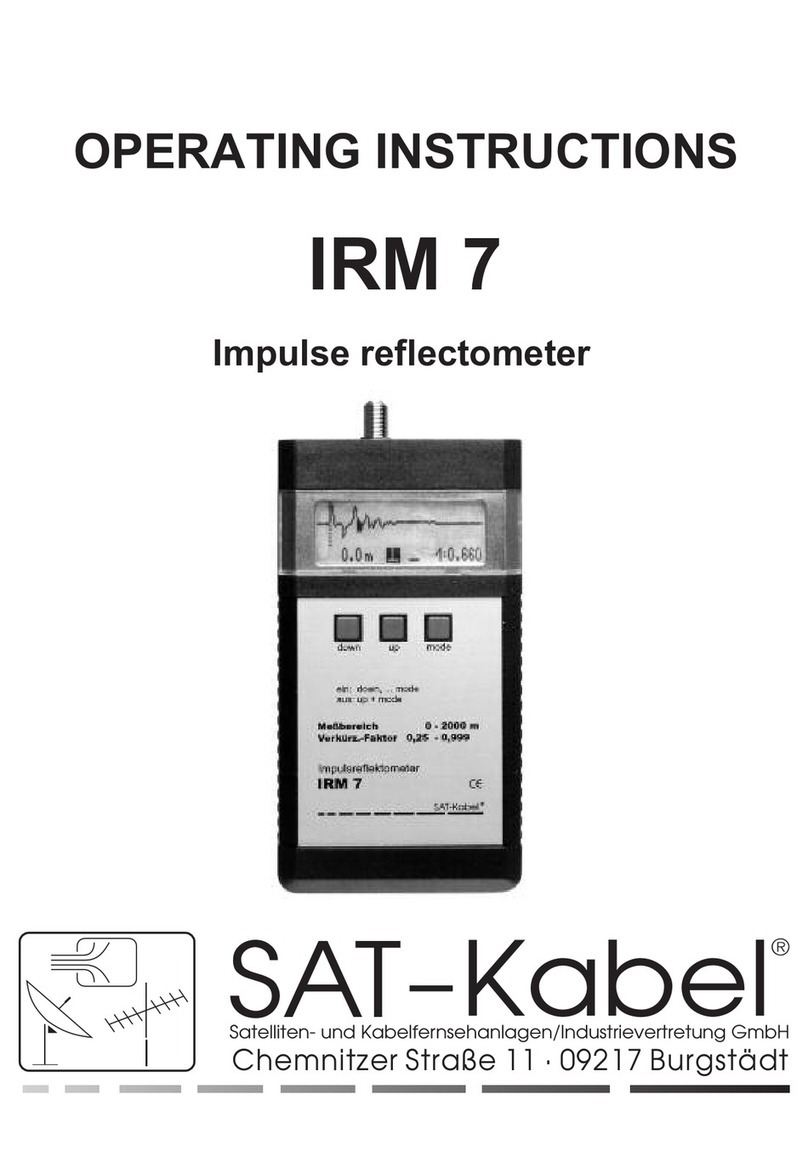
The is a impulse reflectometer, processor controlled, with LCD display for check and
locate faults in telecommunication and power cables. For a more accurate analysis the
return loss of coaxial cables is measured additionally. It is handy and easy to operate. The
special features are:
already 20 cable types are pre-programmed, additional types can be added in the
menu
length measurement at the leading edge of the reflected pulse
return loss measurement on the reflected pulse
pulse amplification adjustable at cable bruise, bad connectors and other
components withtoo less return loss
IRM 5
!
!
!
!
.
1 , incl. high-quality NiMH accumulator
1 plugin charging device AC/AC
1 operating instructions
Symmetrical measuring cable with adapter
F measuring cable with adapter
Car charging cable
Plastic case
Imitation leather bag
Protective housing green, with carrying strap
IRM 5
optional available:
SMK-IRM
MKA 150HQ
KFZ-LK
TKSI
KLT
SGW
Connect the plugin charging device (containing in
the delivery volume) to the charging socket of the
IRM 7 (ø5.5/2.1 mm, plus pole inside). The power
supply voltage (11...24 V) and charging control is
shown on the display.
Fed into a cable measuring pulses are reflected by the inhomogenities of the cable
impedance (cable fault) and made visible on the display. From the form and the time
displacement of the reflection, the nature of the fault and the fault distance can be
determined. It is also advisable to acquire practical experience by sample
measurements.

5
©2012 SAT-Kabel GmbH
3 Operating keys
LCD-Display
Charging socket
Measuring socket
123
down up mode
123
down up mode
= push long the single key >1 s
(here key 3)
= simultaneously push long two keys >1 s
(here keys 1 and 2)
= simultaneously push long two keys >1 s
(here keys 1 and 3 – reserved for storage)
= push shortly the single key (here key 3)
= push shortly one of the two keys
(here key 2 or 1 – one step forward /back)
5. Important notes
6. Operational elements
•
• Do not expose incident solar radiation, heath and extreme coldness!
• The working temperature range is 0 °C until +40 °C
• Avoid shocks by bumps or falling down. We recommend the use of the
imitation leather bag.
• The F-measuring socket is a high-quality component. This one is
designed for a maximum diameter of 1.1 mm of the inner conductor. We
recommend for a good care of the socket to use a measuring cable with
F-connector plus an according adapter.
Measurement only on strain-free objects!
Switch on |
|
1
2
Push button 1 and then button 2.Now select with buttons 1 and
2 to the desired cable type and then press button 3 –
Propagation factor and cable loss are preset for the
measurement
Push button 1 and then button 3, selection of the cable type is
skipped –propagation factor and cable loss must be yet adjusted
manually to measure .
7. Operating
7.1 Operating functions standard

6©2012 SAT-Kabel GmbH
7.2 Advanced operating functions
7.2.1 Pulse amplifier
7.2.2 Parameter of length measurement adjust
Resolution | Firstly can be adjusted in the menu the resolution of the trace in steps. By
long pressing of the button 3 - until the icons appear inverted - you get to the first
parameter of the measurement. Here can be set with the buttons 1 or 2 the required
value.
During switching on the state of charge of the battery in the display will briefly appear
(battery is full: ca. 7 V, low battery: ca. 5.5 V). After switching on the is the length
measurement mode. Here enter additional settings for the measurement to be made
(see 8.2).
Push buttons 2 and 3 simultaneously until display disappears
Without operation the device switches off itself after four minutes. If the battery voltage
drop to 5.9 volts, there is a fade-in on the display. At 5.5 V the device switches off to
protect the battery.
IRM 5
Switch off
Move the cursor
Menu
Save settings
button 1 »down« press briefly – one step left
button 2 »up« press briefly – one step to the right
Hold down for quick cursor movement the respective key
button 3 »mode« push long (L) – a menu item continue
button 3 »mode« push short (K) – a menu item back
push button 1 and 3 simultaneously– the previous settings will
remain permanent
To increase the sensitivity of the , the gain can be adjusted in 4-dB steps from 0 to
36 dB. The gain »V« is starting from the length display to select by shortly pressing the
button 3. With the buttons 1 and 2 the gain can be stepwise changed. Set it back by a
short push on button 3.
IRM 5

7
©2012 SAT-Kabel GmbH
propagation factor
Filter
pulse width
Resolution
measuring trace
(without reflection)
transmit pulse (0,0 m)
Cursor
7.2.3 Vertical resolution
By long pushing of the keys 1 and 2 the zoom can be switched on or off. Referred to the
operating scheme on page 6 and 7, the zoom only can used to functions under the dashed
line. If the zoom is switched on, the entire display is used for the display of the measuring
curve. An already set gain keeps remained. The zoom can switch off by a repeated long
pushing of the keys 1 and 2.
If you want immediately after switching on the to have a certain setting of the
resolution available, it will be stored by pressing button 1 and 3.
IRM 7
Pulse width|
Filter |
Storage space for propagation factors |
Propagation factor|
After repeated long pressing of button 3 (until icon inverted), the pulse
width can be changed. Rule of thumb: short cable - short pulse
Next lets switch a filter. This can make at a restless trace by interference from
external voltages a better visibility. The disadvantage of pulse reflectometer is generally:
The presentation of the measured curve is delayed. In our case, at about three seconds.
The next setting option is to select a stored
propagation factor. If the propagation factor is not already selected when switched on or
it will need a change in use, this can be done here.
As the last the propagation factor can be adjusted manually by
repeatedly long press of the button 3. The propagation factor must always be set
accordingly before measuring the cable.
If the necessary settings have been made, by briefly pressing button 3 the parameter
settings are stepwise leaving again.
7.2.4 Setting start mode

8©2012 SAT-Kabel GmbH
0.80 / 3.50 CPE
ON
P: 1 v/c=0.83 5.7 dB
8. Measuring with the pulse reflectometer
8.1 Basic principle
The basic physical principle is the echo. There are here signals sent out in e.g. the form
of sound. If they hit an obstacle, then a part of it is sent back again, therefore reflected.
Simple examples are the echo of a rock wall or the sonar in the maritime.
This principle works the same as well on electric lines. Only one takes as a signal
electrical pulses - one can not call into a cable. It therefore is sent these impulses into a
cable and must only measure the time after which a reflection of it arrives
7.3 Change of the cable characteristic values
1|To enter the programming mode, when switched off the device, the buttons 1 +2 are
to press simultaneously so long until the display of the memory locations appear.
2|
3
By shortly pressing of the button 3 parameter to be changed are to be selected
(inverted display) and to change by the buttons 1 and 2. Unused memory locations can
be displayed and disappear here with the parameter »ON« or »OFF«. Disappeared
storage locations do not appear when switching on.
The adjustable parameters are:
0.80 – diameter inner conductor
3.50 – diameter screening
CPE – dielectric
ON/OFF – memory location displayed/disappeared
P: 1 – memory location (e. g. 1)
v/c=0.83 – propagation factor – 0.83 here
5.7 dB – cable attenuation at 100 m at 50 MHz
The saving is done by simultaneously pressing buttons 1 and 3 – DO NOT FORGET!|
If necessary the cable parameters can be changed in the memory locations or also add
new ones. It is essential to ensure to work very carefully, because these values are
critical for each measurement. It may happen, for example, that the propagation factor
must be determined first. A method is described under item 8.2.

9
©2012 SAT-Kabel GmbH
back at the sending point. To get accurate results, you need to pay attention to
something: e. g., that the cable offers a resistance to the signals. This in turn depends on
the structure of the cable. There is except of the cable loss still a very important
parameter - the propagation factor. Very important for coaxial cable is the characteristic
impedance and consequently the adaptation or matching. On this basis the
measurements are made.
For the practitioner the inner workings of a pulse reflectometer is not essential. The
manufacturer takes care of this. More important is to get involved with the process of a
practical measurement. For it must be said in advance that measurements with a pulse
reflectometer the most diverse displays shown. Therefore practical experiences that
include test measurements and tests, are a prerequisite for reliable interpretation of the
displayed waveforms. Here applies the old saw »Practice makes perfect!«
Before to further details still 3 basic principles in practice:
• Only measure on de-energized cables!
The input of the device is NOT designed for high voltages (max. 65 V )
• If possible measure of both cable ends. This increases the accuracy.
• Work for longer cables with an assistant. It simplifies recognition of the
correct cable end
AC/DC
8.2 Propagations factor (v/c or pulse velocity)
The Propagation factor (v/c or pulse velocity) declares the velocity of electrical signals in
the cable in relation to the speed of light.The propagation factor of the cable under test must
always preset before the length measurement. If the propagation factor is unknown, a
approximate value is set and the fault is determined from both ends of the cable
P
Power cables 0.49–0,57, (ca. 0.53)
Coaxial cable with PE dielectric 0.66
Coaxial cable with foam-PE 0.77–0.85
Air isolation 0.88–0.92
ropagations factors of standard cable
Measuring of the propagation factor (v/c) of the cable
Connect a cable with known length (e.g. 100 m) on the . Set the cursor on the cable
length and change the propagation factor so that the pulse echo appears behind the cursor.
IRM 5

10 ©2012 SAT-Kabel GmbH
Measuring cursor
determined length propagation factor
at
8.3 Length and distance measurement - for the practitioner
The main application of a pulse reflectometer is determining the cable length, either the
length of a laid cable or the distance routed to a certain modification, such as cable
failure, inserted component. There are only two ideal states:
1. The cable matches - only transmit pulse recognizable
Resistance equal to 75 ohms (coaxial cable)
2. The cable has mismatches - there will be reflections
The 2. state in turn knows also two ideal cases:
1. The cable end is open - the transmit pulse and reflection
Resistance is greater than 75 ohms - reflected pulse upward
2. The cable end is shorted - transmit pulse and reflection
Resistance is less than 75 ohm - reflected pulse down
On the basis of this behavior can quickly an open or a shorted cable end are recognized.
Even in longer cables if the open end is short-circuited by an assistant at intervals, so
the cable end can be seen by changing deflection of the reflected pulse from top to
bottom and vice versa clearly.
Now missing is the distance to the reflection point, so the cable end or the defective part
in the cable or a component (connector, tap, etc.). For it the cursor is required. This is
positioned with buttons 1 and 2 to the leading edge of the first recognizable reflection.
Immediately to the left bottom of the screen is displayed the distance in meters.

11
©2012 SAT-Kabel GmbH
length measuring range 0-100m
(minimum resolution of 1 m here)
length measuring range 0-25 m
(minimum resolution of 0.2 m here)
changed pulse width
narrow pulse
normal pulse width
fault location
(open cable here)
could also be a fault –
here, however, a well-known cable
connection by using a
so-called »forward wire«
cable type from storage location 15
may be a further defect, but
first is the error on the cursor
to eliminate
In measurements with pulse reflectometer always leading edge to leading
edge of the pulses is measured. For some devices it has to be positioned a
second cursor. At the it has been done internally, so that only one
cursor is needed. It should be a device for the practitioner.
IRM 5
It is usually went to the first clear reflection in the trace. Subsequent »spikes« are
further defects or reflections of the first reflection, usually seen at the same distance
and a smaller deflection. With several »defects« in the cable must always the first be
removed in order to measure accurately the next again.
As a second setting as required, can the pulse width be adjusted (see above). In general,
however, is worked with the normal setting of 20 ns. Only for very short cable lengths, a
narrow pulse is to be used, so that the transmitted pulse does not already covers a fault
location in the immediate vicinity. For extremely long cables (power cables), however, a
wider pulse is necessary to have enough energy for the long distance – that due to cable
resistance the pulse in the resolution of the display does not disappear.
Forward wire | This is a coaxial cable having a known length (for example
10 m), which is inserted before the actual DUT. The purpose of this cable
is that when a fault location immediately after the beginning of this cable
is to be badly distinguished from the original pulse or possibly even
hidden. By this forward wire this point, however, is shifted by a known
length to the right. They will appear in the actual distance plus 10 meters
of forward cable.
Thus the distance is to be determined as accurately as possible, firstly the resolution of
the display has to adjust according the measured cable length .

12 ©2012 SAT-Kabel GmbH
An important statement about the quality of a cable or components present in the line
allowed the return loss, also reflection attenuation (dBRL) called. Since most taps and
splitter have a lower return loss as coaxial cable, it is of interest if these are still intact.
In intact coaxial cables the return loss is in the range of about 45 ... 65 dB. Everything
else indicates more or less an existing fault. For the passive components, the set point
can be found in the data sheets. If the measured values are below, there are often
already unexplained complications, often at the digital signals in the return path.
To measure the return loss with the , it is necessary first selecting the appropriate
type of cable ( switch on with button 1 then button 2). After selecting the cable type then
push button 3. Now appears in the bottom-right, the return loss in dBRL. Top right is the
selected storage location of the cable type displayed. The cursor is now to set on the
peak of the pulse of the reflection under test, and the return loss can be read on the
display. The IRM determines in a specified area selected by the device from the cursor to
the lowest value of the return loss. Is the cable attenuation set correctly, the
shows the actual return loss (local return loss). The pulse attenuation of the cable is
deducted from the .
IRM 5
IRM 5
IRM 5
In the third setting, a filter can be switched to suppress disturbances. However this
slows down the entire measurement process.
The fourth, most important adjustment relates to the structure of the cable. This results
in the cable-specific propagation factor. This is before the measurement, so when switch
on the IRM 7, to choice as cable type from the stored list or to enter manually.
The measuring curves are in practice however usually between those relatively easy to
interpret curves. The reasons are eg.:
usually be seen in the form of a small sine wave; on thick coaxial
cable only with high measurement gain, at very good connectors (generally the thick,
large) almost never to find
in the form similar to a sine wave, usually also asymmetrical. The size
reflects the state.
Measuring curve linear in the range of adaptation, however some
sections strongly serrated, also by mechanical overloads
Cable connector |
Taps, splitter |
Water in the cable |
8.4 Measuring the return loss - for the practitioner

13
©2012 SAT-Kabel GmbH
return loss
return loss against 0 dBRL
error - this cable end open
storage location of the cable type
9. Technical data
Measuring ranges
Resolution switchable
Accuracy of the measuring range
Propagation factor
Storage places for cable type and propagation factor
already 20 pre-programmed
Sensitivity
Digital filter switchable for suppression of
external voltages on the cable
Output F-socket
Output
Operation
Power supply NiMH-accumulator 6V/750 mAh; AC/AC adapter
Powwer consumption
Dimensions
Weight
0–2000 m
0.25m/1m/4m,
0.2 %
0.250–0.999
30
Dynamic 44 dB
70 dB
Impedance 75 Ohm
pulse 4 V, 5 ns / 20 ns / 100 ns wide
Display LCD 120 × 32 pixel, illuminated
with 3 keys
80 mA
157mm×84mm×30mm
300 g

14 ©2012 SAT-Kabel GmbH
10. Operating scheme IRM 5
Measuring of the return loss
after Switch off:
Store values:
Cable selection
(storage place)
Measuring curve
Cursor
Resolution
0,2/…/4 m
Resolution
0,2/…/4 m
Gain
V: 0/4/8/…/36
Pulse width
5/20/100 ns
Filter
(on/off)
In all measurement menus
– 44 dB dynamics
– high vertical resolution
vertical resolution
high / normal

15
©2012 SAT-Kabel GmbH
©SAT-Kabel®
Measuring without return loss
after Switch off:
Store values:
Cursor
Resolution
0,2/…/4 m
Gain
V: 0/4/8/…36
Pulse width
5/20/100 ns
Filter
(ein/aus)
Storage place for
propagations factor
Propagations factor
0,25…0,999
= Push key long (>1 s)
= Do not push the key!
= Push shortly the key
= Alternative push key shortly
Legend:

16 ©2012 SAT-Kabel GmbH
program cable type cable diameter kind of propagation cable attenuation at
ielectricplace designation inner conductor dielectric d factor 50 MHz at 100 m
P 1 mini cable 0.41 mm 1.90 mm CPE 0.78 10.9 dB
P 2 H 123 0.65 mm 2.90 mm CPE 0.85 7.5 dB
P 3 COAX 12 0.70 mm 4.60 mm PF 0.66 5.6 dB
P 4 H 121., MK 75 0,80 mm 3,50 mm CPF 0,84 5.7 dB
P 5 H 126 DUOBOND PLUS, KOKA 799 1.00 mm 4.60 mm CPE 0.82 4.5 dB
P 6 MK 15, LCD 90 1.02 mm 4.40 mm CPE 0.85 4.3 dB
P 7 75100 AKZ 3-S (RG6) 1.00 mm 4.60 mm CPE 0.85 4.4 dB
P 8 TELASS B1,1/7,3 1.10 mm 7.25 mm PE 0.66 3.8 dB
P 9 1 ikx 1,1/7,3; KOKA 741 1.10 mm 7.30 mm PE 0.66 3.3 dB
P 10 LCD 95, DIGITAL 94 1.13 mm 4.80 mm CPE 0.85 4.3 dB
P 11 PRG 11 1,55 mm 7.25 mm CPE 0.81 2.7 dB
P 12 LCM 14, MK 15, KOKA 7 1.63 mm 7.20 mm CPE 0.84 2.8 dB
P 13 COAX 6 (LG) 1.70 mm 6.95 mm CPE 0.89 2.3 dB
P 14 COAX 4 2.20 mm 10.2 mm CPE 0.82 1.9 dB
P 15 1nkx 2.20 mm 8.80 mm PEH 0.88 1.8 dB
P 16 1qkx 3.30 mm 13.50 mm PEH 0.88 1.2 dB
P 17 COAX 3 3.40 mm 14.9 mm CPE 0.84 1.3 dB
P 18 1skx 4.90 mm 19.40 mm PEH 0.88 0.9 dB
P 19 75-7-12 D 2.60 mm 10.00 mm AIR 0.85 1.6 dB
P 20 75-7-16 D 3.80 mm 13.80 mm AIR 0.92 1.1 dB
11.
Stored cable
data
(State 01/2012)

17
©2012 SAT-Kabel GmbH

18 ©2012 SAT-Kabel GmbH

19
©2012 SAT-Kabel GmbH
The surface of the housing can be cleaned with a dry, soft and lintfree cloth. Do not use
aggressive solvents for the cleaning.
12. Cleaning
13. State July 2006Guarantee
For this instrument will be granted a service life (in following called guarantee) to
following conditions:
This guarantee is valid for new instruments purchased in Germany.
New instruments and their components, which are defective because of production
faults and/or material faults, are repaired from SAT-Kabel®.
For wear parts, like accumulators, keyboards, housings, bags, connecting cables
this guarantee is valid for 6 month from the purchasing date.
The guarantee claim expires at matings by the purchaser or third persons.
At defects, caused by improper handling or operating, by wrong installation or
store, by improper connection or mounting, no guarantee is granted.
For not justified demand of our service we charge for our service the usual
payment for material, working hours and forwarding costs.
Repairs are only made with filled service covering.
Forms for service coverings and further information are found in the standard form
contracts under:
+
+
+
+
+
+
+
www.sat-kabel.de

©2012-09-20 SAT-Kabel®
Errors, technical amendmends and developments are subject to change without notice!
Satelliten- und Kabelfernsehanlagen/Industrievertretung GmbH
Telephone: +49 3724 6665-0
Telefax: +49 3724 6665-44
SAT-Kabel®
Table of contents
Other SAT-Kabel Measuring Instrument manuals

SAT-Kabel
SAT-Kabel IRM 5 MMC User manual

SAT-Kabel
SAT-Kabel CATVmeter User manual
SAT-Kabel
SAT-Kabel TVmeter HD-T Setup guide

SAT-Kabel
SAT-Kabel AMS-FS433 User manual

SAT-Kabel
SAT-Kabel SPM 6PC User manual
SAT-Kabel
SAT-Kabel IRM?70 SD User manual

SAT-Kabel
SAT-Kabel IRM 7 User manual

SAT-Kabel
SAT-Kabel IRM?20 User manual
SAT-Kabel
SAT-Kabel SPM 22 PF User manual
Popular Measuring Instrument manuals by other brands

BC Group International
BC Group International BC Biomedical ESU-2000A user manual

PCB Piezotronics
PCB Piezotronics ICP 356A04 Installation and operating manual

Campbell
Campbell HMP60 instruction manual

Wilcoxon
Wilcoxon MachineryMate 200 operating guide

Nidec
Nidec FG-7000TA Operation manual

EEC
EEC EST-300 Series user manual