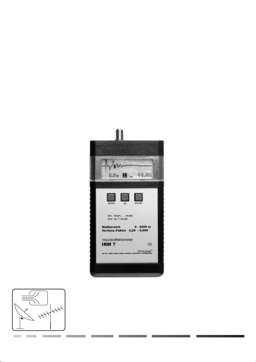
SAT-Kabel IRM 7 User manual

IRM 7
OPERATING INSTRUCTIONS
Impulse reflectometer
Chemnitzer Straße 11 .09217 Burgstädt
Satelliten- und Kabelfernsehanlagen/Industrievertretung GmbH
SAT
Kabel
-
®

General
1 IRM 7 incl. high-quality NiMH accumulator
1 plugin charging device AC/AC
1 operating instructions
optional available: Imitation leather bag KLT or KLT 2
Measuring cable with adapter MKA 150 HQ
Plastic case TKSI
nd extreme coldness!
The working temperature range is 0 °C until +40 °C
Avoid shocks by bumps or falling down. We recommend the use of the imitation leather
bag.
The F-measuring socket is a high-quality component. This one is designed for a
maximum diameter of 1.1 mm of the inner conductor. We recommend for a good care
of the socket to use a measuring cable with F-connector plus an according adapter.
!
!
!
!
+
+
+
+
Delivery volume
Zur Beachtung!
The is a impulse reflectometer, processor controlled, with LCD display for check and locate
faults in telecommunication and power cables. For a more accurate a
IRM 7
nalysis the return loss of
coaxial cables is measured additional. It is handy and easy to operate.
already 20 cable types are pre-programmed, additional types can be added in the menu
length measurement at the leading edge of the reflected pulse
return loss measurement on the reflected pulse
pulse amplification adjustable at cable bruise, bad connectors and other components with
too less return loss.
The special features are:
Measurement only on strain-free objects!
+Do not expose incident solar radiation, heath a
Charging
Connect the plugin charging device (containing in the delivery volume) to the charging socket of the
(ø5.5/2.1 mm, plus pole inside). The power supply voltage (11...24 V) and charging control is
shown on the display.
IRM 7
M
Wir danken Ihnen für den Kauf dieses Produktes.
Diese Bedienungsanleitung soll Ihnen die Funktionen des Gerätes vermitteln und den
Gebrauch erleichtern. Sollten Sie Fragen oder Anregungen zur weiteren
Verbesserung haben, lassen Sie es uns wissen.
zum Gerät
-2-
We thank you for buying of a product of the company SAT-Kabel .
This operating instructions shall help you to understand the functions of the instrument and to ease
its use. If you have questions about this instrument or suggestions for further improvements,
please get in touch with us.
®

Measuring ranges
Resolution switchable
Accuracy of the measuring range
Propagation factor
Storage places for cable type and propagation factor
already 20 pre-programmed
Sensitivity
Digital filter switchable for suppression of
external voltages on the cable
Output F-socket
Output
Operation
Power supply NiMH-accumulator 6V/750 mAh; AC/AC adapter
Powwer consumption
Dimensions/weight
0–2000 m
0.1 m / 0.2 m / 0.4 m / 1 m / 2 m / 4 m,
0.2 %
0.250–0.999
30
Dynamic 64 dB
80 dB
Impedance 75 Ohm
pulse 4 V, 2 ns / 20 ns / 100 ns wide
Display LCD 120 × 32 pixel, illuminated
with 3 keys
90 mA
157 × 84 × 30 [mm] / 300 g
Function operated from:
Switch on key 1 after that key 2 or key 3 (according of the desired mode)
Switch off keys 2 und 3 simultaneously
Cursor move key 1 “down”–one step to left
key 2 “up”–one step to right
Menu key 3 “mode”long –one menu point forward
key 3 “mode”shortly –one menu point back
W
Operational elements
-3-
Technical data, features
Operating functions standard
3 Operating keys
LCD-Display
Charging socket
Measuring socket
123
down up mode
123
down up mode
= push long the single key >1 s
(here key 3)
= simultaneously push long two keys >1 s
(here keys 1 and 2)
= simultaneously push long two keys >1 s
(here keys 1 and 3 –reserved for storage)
= push shortly the single key (here key 3)
= push shortly one of the two keys
(here key 2 or 1 –one step forward /back)

-4-
Operating:
Cursor movement:
:
with key 1 or 2
Keys:“”=1;“”=2;“”=3
Switch on at use of the given cable types:
Fast Cursor movement
Fault location:
ATTENTION ! Do not measure on live cables !
(Electric strength max. 65 V)
down up mode
Switch on the with key 1, push after that key 2. Select the cable type with the keys 1 and
2, after that push key 3 –propagation factor and cable attenuation of the cable types are preset
at the measurements.
Keep pushed key 1 or 2.
IRM 7
Switch on:
Switch off:
Push key 1, after that push key 3. (accumulator full app. 7 V, empty app. 5.5V)
Push simultaneously key 2 and 3, after 4 min. inactivity automatically.
If the accumulator voltage drops to 5.9 V, a fade-in happens on the display.
At 5.5 V the IRM switches off itself.
At 0 m the positive transmitting pulse can be seen. If the connected cable is open on its end, an
additional positive going pulse appears on the display. In the case of a shorted end of the cable
a negative going pulse appears reflected from the cable end (pulse echo).
Adjust the cursor to the beginning of the pulse and read the cable length. If the cable is
terminated with a resistance equal to the impedance of the cable, no reflexion occurs when
the cable is faultless. In the case of breaks, contact faults in sleeves, short circuits or
taps/splitter in the sector to be tested, the distance to the cable beginning can be
determined by the pulse echo.
If wide pulses are used for the measurement, the echoes are stronger, but faultless taps/splitter
cause then strong echoes.
M
Selection of length range, resolution, output pulse width, digital filter, storage place or
propagation factor:
Outgoing from the length measurement:
Permanent storage:
Back:
Push long key 3 until the desired symbol appears
inversely. Change of the selected value with the keys 1 and 2.
Push keys 1 and 3 simultaneously.
Push short key 3.
M
Measurement principle:
The measuring pulse fed into the cable will reflected by inhomogeneity of the cable i
mpedance (cable faults) and showed on the display.
The distance and the kind of the fault can be determined out of the shape and the time
setting of the reflection. (Practical experience can be obtained by test measurements).
Z

-5-
Measurement of the cable attenuation/100m at 50 MHz
Pulse amplifier
Connect app. 100–200m cable on the , shorted or open end (all pulse energy will be
reflected). Select pulse width 20 ns. Set cursor on the pulse echo. Set the value of the cable
attenuation so that the return loss will be 0 dBRL. Read the attenuation value.
To reject or decrease interference voltage on the cable, which affect the displayed waveform, a
digital mean filter “Fi”can be connected. The display of the waveform will be delayed to 3
seconds.
IRM 7
:
Digital filter:
:
Start mode:
To increase the sensitivity of the the gain can be set in steps of 4 dB from 0 to 36 dB. The
gain ”V”can be set by short pushing of the key 3 proceeding from the length display.
IRM 7
If at a certain resolution the keys 1 und 3 are pushed simultaneously, this resolution will be
active at the switch on of the .IRM 7
S
Measuring of the return loss (reflexion attenuation dBRL):
This measurement is only possible at before selected cable types. The cursor should be set to
the pulse peak and the return loss can be read on the display in the right below corner. The IRM
finds out the lowest value of the return loss in a range determined by the instrument. At the top
right can be read the storage place of the cable type. If the cable attenuation is set correctly, the
displayed value of the return loss is the real value (local return loss). The pulse attenuation of
the cable is calculated by the .
For measurement of the return loss is a pulse width of 2 ns (smallest pulse) best suitable (if
the pule is yet visible).
IRM 7
Propagation factor:
The Propagation factor (v/c or pulse velocity) declares the velocity of electrical signals in the
cable in relation to the speed of light.
The propagation factor of the cable under test must always preset before the length
measurement. If the propagation factor is unknown, a approximate value is set and the fault is
determined from both ends of the cable
MZoom
By long pushing of the keys 1 and 2 the zoom can be switched on or off. Referred to the
operating scheme on page 6 and 7, the zoom only can used to functions under the dashed line.
If the zoom is switched on, the entire display is used for the display of the measuring curve. An
already set gain keeps remained. The zoom can switch off by a repeated long pushing of the
keys 1 and 2.

-6-
Operating scheme IRM 7 Software version 3.09.4 ©
Zoom
on/off
Measuring of the return loss Measuring without return loss
after a
Switch off: Switch off:
Store values: Store values:
cable selection
(storage place)
Measuring curve
Cursor
C
Resolution
0.1/0.2/…/4 m
R
Resolution
0.1/0.2/…/4 m
Gain
V: 0/4/8/…/36
G
Pulse width
2/20/100 ns
P
Filter
(on/off)
F
Our off all menu points
(not at selection of the
cable type)
- 64 dB dynamics
- full display

-7-
©SAT-Kabel®
Measuring without return loss
a after Switch off:
S Store values:
Cursor
R
Resolution
0.1/0.2/…/4 m
R
Gain
V: 0/4/8/…36
P
Pulse width
2/20/100 ns
F
Filter
on/off)
Storage place for
propagations factor
Propagations factor
0.25…0.999
= Push key long (>1 s)
= Do not push the key!
= Push shortly the key
= Alternative push key shortly
Legend:

Change of the cable characteristic values:
!
!
!
!
In switched off condition push the keys 1 and 2 simultaneously so long, until the display of the
storage places appears.
Select by shortly pushing of the key 3 the parameter to be changed (inverse display) and
change with the keys 1 and 2.
Not used storage places can be faded in or out with the parameter ”ON“resp. ”OFF”. Faded
out storage places don't appear any more at the switch on.
The changeable parameters are
inner diameter
outer diameter
dielectric
fade in/out of the storage place
storage place (e.g. 1)
propagation factor
cable attenuation
Storage by simultaneously pushing of the keys 1 and 3.
:
0.08 –
3.5 –
CPE –
ON/OFF –
P: 1 –
v/c –
5.7 dB –
-8-
0.80 / 3.50 CPE
ON
P: 1 v/c=0.83 5.7 dB
H
Measuring of the propagation factor (nvp-value) of the cable:
Connect a cable with known length (e.g. 100 m) on the . Set the cursor on the cable length
and change the propagation factor so that the pulse echo appears behind the cursor.
IRM 7
Propagation factors
Power cables
Coaxial cable with PE dielectric
Coaxial cable with foam-PE
Air isolation
:
0.49–0.57, (ca. 0.53)
0.66
0.77–0.85
0.88–0.92
M

-9-
Here are shown some typical curves of the use of the . But it must be known, that measure-
ments with an impulse reflectometer result in varied displays. Therefore are practical experiences
IRM 7
prerequisite for a certain interpretation of the displayed measuring curves including test
measurements and trials.
M
Measuring with pulse reflectometer –directions out of the practice
This examples show three standard situations. The entire transmitting pulse(decreased at the
cable attenuation) is reflected and the result is definite.
The curves show additional among others the quality of the cable. The upper curve shows a high
quality new cable. The next two curves show slight waves caused by using signs. From experience
this cable can be further still used More precise results you can achieve by the measurement of the
return loss, with this instrument no problem.
Attention! The indentation what you can see after a cable end (or component), are further pulses
caused by the repeatedly pass through of the cable. To eliminate such a n error source, a check with
second person is to make, which on the open end of the cable make a short circuit at disposition.
This caused a tilting of the reflected pulse and the right end of the cable under test can be
determined. Please note the important advice at this method:
It is very important for accurate measurements to measure the cable under test from both sides.
Furthermore the selection of the right propagation factor is most important for the accurate length
measurement of the . Therefore you find on the next page a table with the already
programmed cable types.
Do not work with the IRM 7 on live cable!
IRM 7
1. This is a display after the switch on of the . You can see the
transmitting pulse and the cursor. The left leading edge of the
transmitting pulse is to align with the cursor by the zero point shift.
Below are displayed from left to right the distance, the selected
pulse, filter(without) and the cable propagation factor.
This ideal curve can also be seen with a correct terminating resistor.
IRM 7
2. Here are used a assembled feed line as test object. The end of the
cable is open, the impedance therefore very high and the
transmitting pulse is reflected. The cursor is located on the leading
edge of the reflected pulse. The distance are displayed correctly
with 10.2 m (the cable was really 10.2 m long)
3. Now the cable has been shorten, the impedance therefore very
low. The transmitting pulse is reflected again, but displayed
downward. This mean short circuit. The cursor is located again on
the leading edge. The distance is also 10.2 m.

-10 - -
Program cable type
place designation -factor
P1CCS 36 GAS 0,41 mm 1,90 mm CPE 0,78 10,9 dB
P2MIDI EXTRA 65 GAS 0,65 mm 3,00 mm CPE 0,83 7,2 dB
P3COAX 12 0,70 mm 4,60 mm PF 0,66 5,6 dB
P4EXTRA 80 GAS 0,80 mm 3,50 mm CPF 0,83 5,7 dB
P5H 126 DUOBOND PLUS 1,00 mm 4,60 mm CPE 0,82 4,5 dB
P6TRISHIELD DIGITAL GAS 1,02 mm 4,40 mm CPE 0,85 4,3 dB
P7QUADRISHIELD DIGITAL GAS 1,02 mm 4,40 mm CPE 0,85 4,2 dB
P8TELASS B1,1/7,3 1,10 mm 7,25 mm PE 0,66 3,8 dB
P91 ikx 1,1/7,3 1,10 mm 7,30 mm PE 0,66 3,3 dB
P10 AMEL SATGAS, SAT300 GAS 1,13 mm 4,80 mm CPE 0,85 4,1 dB
P11ALM DIGITAL SAT/ GAS 1,13 mm 4,80 mm CPE 0,85 3,9 dB
P12 PA1,63/50 SATGAS 1,63 mm 7,20 mm CPE 0,84 3,0 dB
P13 PA1,63 ALL DIGITAL- SAT
(AP/Tragseil)
P14 COAX 6 (LG) 1,70 mm 6,95 mm CPE 0,89 2,3 dB
P15 1nkx 2,20 mm 8,80 mm PEH 0,88 1,8 dB
P16 1qkx 3,30 mm 13,50 mm PEH 0,88 1,2 dB
P17 75-7-12 D 2,60 mm 10,00 mm AIR 0,85 1,6 dB
P18 75-7-16 D 3,80 mm 13,80 mm AIR 0,92 1,1 dB
P19 1skx 4,90 mm 19,40 mm PEH 0,88 0,9 dB
P20 75-7-G 1,20 mm 8,00 mm PE 0,67 4,0 dB
1,63 mm 7,20 mm CPE 0,84 2,7 dB
cable diameter kind of propagation cable attenuation at
inner conductor dielectric dielectric 50 MHz at 100 m
Stored cable data
IRM 7

-11 -
P
Cleaning and maintenance
The surface of the housing can be cleaned with a dry, soft and lintfree cloth. Do not use
aggressive solvents for the cleaning.
This operating instruction has been drown up . Errors, technical
amendmends and developments are subject to change without notice!
Updated operating instructions in PDF form can be also downloaded from our internet
homepage. ( )www.sat-kabel.de
to the best of our knowledge
Guarantee
State July 2006
For this instrument will be granted a service life (in following called guarantee) to following
conditions:
This guarantee is valid for new instruments purchased in Germany.
New instruments and their components, which are defective because of production
faults and/or material faults, are repaired or are replaced from SAT-Kabel® against a
corresponding instrument.
For wear parts, like accumulators, keyboards, housings, bags, connecting cables this
guarantee is valid for 6 month from the purchasing date.
The guarantee claim expires at matings by the purchaser or third persons.
At defects, caused by improper handling or operating, by wrong installation or store, by
improper connection or mounting, no guarantee is granted .
For not justified demand of our service we charge for our service the usual payment for
material, working hours and forwarding costs.
Repairs are only made with filled service covering.
(Forms for service coverings and further information are found in the standard form contracts
under:
)
+
+
+
+
+
+
+
www.sat-kabel.de

IRM7-11/2007 CDX3 ©SAT-Kabel®
Errors, technical amendmends and developments are subject to change without notice!
SAT-Kabel®
Satelliten- und Kabelfernsehanlagen/Industrievertretung GmbH
Telephone: +49 3724 6665-0
Telefax: +49 3724 6665-44
E-Mail: [email protected]
Internet: www.sat-kabel.de
Table of contents
Other SAT-Kabel Measuring Instrument manuals

SAT-Kabel
SAT-Kabel IRM?20 User manual

SAT-Kabel
SAT-Kabel SPM 22 PF User manual

SAT-Kabel
SAT-Kabel AMS-FS433 User manual

SAT-Kabel
SAT-Kabel CATVmeter User manual

SAT-Kabel
SAT-Kabel IRM 5 User manual

SAT-Kabel
SAT-Kabel IRM?70 SD User manual

SAT-Kabel
SAT-Kabel IRM 5 MMC User manual

SAT-Kabel
SAT-Kabel TVmeter HD-T Setup guide

SAT-Kabel
SAT-Kabel SPM 6PC User manual