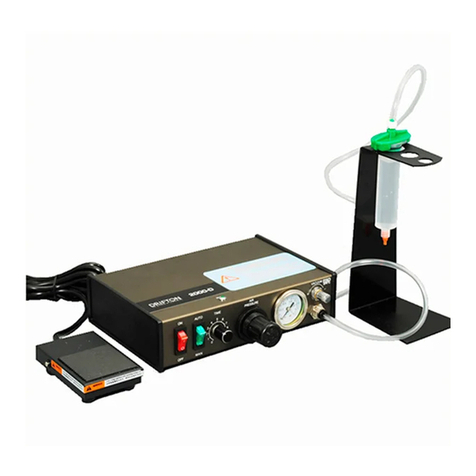
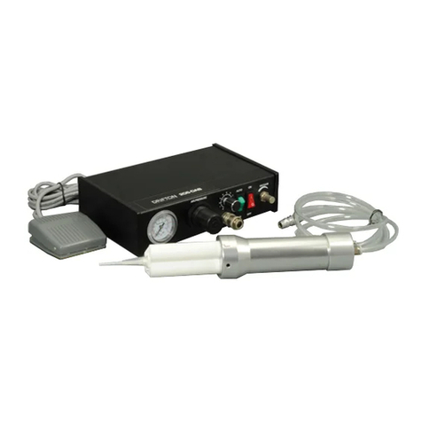
DRIFTON 2004-DE User manual

Drifton A/S
Avedoereholmen 84, 2650 Hvidovre, Denmark
Tel: 0045-5372 8090, Fax: 0045-3677 3633
Web: www.drifton.eu / www.drifton.dk E-mail: info@drifton.dk
Drifton High Precision Liquid Dispenser
Operation Manual (GB)
2004-DE
2004-DT
2004-DB

2
Introduction
You have selected a reliable, high quality, high precision dispenser from Drifton A/S. The dispenser will
provide you with years of trouble-free, productive service. This operation manual will help you maximize the
usefulness of your new dispenser.
Please spend a few minutes to become familiar with the controls and features. Follow our recommended
testing procedures. Review the helpful information we have included, which is based on more years of
industrial dispensing experience.
Most questions you will have are answered in this Operation Manual. However, if you need assistance,
please do not hesitate to contact Drifton A/S at telephone 0045-5372 8090 or info@drifton.dk or an
authorized distributor
Our goal is to build not only the finest equipment and components, but also to build long-term customer
relationships founded on superb quality, service, value and trust.
Drifton A/S
The science of dispensing

3
Contents
Introduction ....................................................................................................................................................... 2
Contents............................................................................................................................................................. 3
Product Safety Statement .................................................................................................................................. 5
Intended User................................................................................................................................................. 5
Regulations and Approvals............................................................................................................................ 5
Qualified Personnel....................................................................................................................................... 5
Personal Safety.............................................................................................................................................. 5
Started................................................................................................................................................................ 6
Principles........................................................................................................................................................... 6
Dispenser Hookup............................................................................................................................................. 7
Drifton 2004-DE - Digital & Circling Dispenser.............................................................................................. 8
Drifton 2004-DE - Specifications.................................................................................................................. 8
Drifton 2004-DE - Connections drawing ...................................................................................................... 8
Drifton 2004-DE - Controls Panel................................................................................................................. 9
Drifton 2004-DE - Setup for Testing........................................................................................................... 10
Drifton 2004-DT - High Precision Digital Display Dispenser........................................................................ 11
Drifton 2004-DT - Specification ................................................................................................................. 11
Drifton 2004-DT - Connections drawing .................................................................................................... 11
Drifton 2004-DT - Controls Panel............................................................................................................... 12
Drifton 2004-DT - Setup for Testing........................................................................................................... 13
Drifton 2004-DB - High Precision Digital Display Cycling ........................................................................... 14
Drifton 2004-DB - Specification................................................................................................................. 14
Drifton 2004-DB - Connections drawing.................................................................................................... 14
Drifton 2004-DB - Controls Panel............................................................................................................... 15
Drifton 2004-DB - Setup for Testing .......................................................................................................... 16
Application Art................................................................................................................................................ 17
1. Making Timed Deposits of Medium to Thick Fluids.............................................................................. 17
2. Changing Deposit Size, Drawing Stripes................................................................................................ 17
3. Setting the deposit size............................................................................................................................ 18
4. How to Use the Vacuum Control ............................................................................................................ 18
5. Piston function......................................................................................................................................... 19
6. Filling the Syringe Barrel........................................................................................................................ 20

4
Suggestions on Settings................................................................................................................................... 21
Helpful Hints................................................................................................................................................... 21
Troubleshooting Guide.................................................................................................................................... 22
Guarantee......................................................................................................................................................... 23

5
Product Safety Statement
Intended User
Use of Drifton equipment in ways other than those described in the documentation supplied with the
equipment may result in injury to persons or damage to property. Some examples of unintended use of
equipment include:
Using incompatible materials
Making unauthorized modifications
Removing or bypassing safety guards or interlocks
Using incompatible or damaged parts
Using unapproved auxiliary equipment
Operating equipment in excess of maximum ratings
Operating equipment in an explosive atmosphere
Regulations and Approvals
Make sure all equipment is rated and approved for the environment in which it is used. Any approvals
obtained for Drifton equipment will be voided if instructions for installation, operation and service are not
followed.
Qualified Personnel
Equipment owners are responsible for making sure that Drifton equipment is installed, operated and serviced
by qualified personnel. Qualified personnel are those employees or contractors who are trained to safely
perform their assigned tasks. They are familiar with all relevant safety rules and regulations and are
physically capable of performing their assigned tasks.
Personal Safety
To prevent injury, follow these instructions:
Do not operate or service equipment unless you are qualified.
Keep clear of moving equipment. Before adjusting or servicing moving equipment, shut off the
power supply and wait until the equipment comes to a complete stop. Lock out power and secure the
equipment to prevent unexpected movement.
Make sure dispensing areas and other work areas are adequately ventilated.
Know where emergency stop buttons, shutoff valves and fire extinguishers are located.
Clean –Remove all electrical and mechanical connections to unit. Apply a small amount of light
detergent onto a moist cloth and wipe surface of unit lightly, cleaning any stains or spilled adhesive.
Maintain –Only use clean dry air and regulated power supply for the unit. Equipment does not
require any other regular maintenance.
Test –Verify operation of features and performance of equipment using the ‘Testing and
installation’ sections within this Operation manual. If necessary, refer to the ‘Trouble Shooting
Guide’ elsewhere in this user guide. A faulty or defective unit should be returned to Drifton or
representative for refurbishment.
Caution: Use replacement parts that are designed for use with the original equipment so that our dispenser
will better work for you.

6
Started
First: Unpack and see the pack list enclosed with the Dispenser, and then check all items. If there is any
discrepancy, please call us immediately.
Second: Power and compressed plant air should be available where the dispenser is to be set up. Be certain
your plant air is properly filtered and dry and a regulated, constant air pressure is supplied to the dispenser.
We have organized this operation manual to provide setup and testing procedures for the High precision
Series dispensers.
Please see the content for the different dispensers.
Next: We will tell you how to dispensing low viscosity fluid using the vacuum control and how to dispense
high viscosity liquid.
Principles
Drifton high precision dispenser series quote air pressure control liquid, Fluid dispensing through high-
precision timing of the pressure pulse control, which could ensure that the correct amount of fluid is applied
at every time, on every part, to every item Time is more precise quantitative also will be prospective more.
Solenoid Valve higher response rate, dispensing speed will be soon
Drifton dispenser components: syringes, the Pistons, high-precision needle, adapter. High precision
controller (timing, pressure), it is easy to operate, small volume. Only use a little electricity and pressure.
Maximum pressure is 7bar; it can be applied to different viscosity of fluid materials, vacuum suction to
prevent of liquid down flow.

7
Dispenser Hookup
1. Connect the air input hose to a plant air source. Set plant air supply within 80 to 100 psi.
2. Attach the air input hose coupling to the dispenser.
3. Plug in the polarized foot pedal connector. Connect the foot pedal to the back of the dispenser
4. Check the voltage label on the input voltage selector cartridge. Connect the power cord into the back
of the dispenser. Connect the power cord into your local power source (AC110V-220V / 50Hz).
5. Attach the 30cc barrel refilled with test fluid, maximum 2/3 full
6. Using the correct Drifton piston insert the barrel. Place the piston down into the barrel.
7. Remove the end cap, connect to the adapter assembly. Twist clockwise to lock.
8. Push the black male quick-connect on the syringe barrel adapter assembly into the front of the
dispenser
9. Remove the tip cap, replace it with an appropriate Drifton tip cap. Place the syringe barrel in the
barrel holder.
10. Initial setup is now complete. At this point you are now ready to set up your dispensing flow rate and
time to suit your application needs.
11. Note: Always use the lowest possible pressure and the largest possible tip size. The combination of
the lowest possible output pressure + largest possible tip size + longest possible dispense duration =
most consistent and accurate deposits.
12. During the initial testing, you will not use the vacuum control. Keep this control shut off (turned
completely clockwise—do not force).

8
Drifton 2004-DE - Digital & Circling Dispenser
Drifton 2004-DE - Specifications
Dispensing time: 0.007S-9.999S
Cycling (interval) time: 0.1S-9.9S
Air Input: 7KgF/cm2
Air Output: 0.1–7KgF/cm2
Repeatability: 0.0005S
Min depot: 0.005ml
Work Frequency: >600 times/minute
Input AC: 110V or 220V 50Hz
Internal Voltage: 24 VDC
Input Power Required: < 15W
Weight: < 3.5Kg
Cabinet Dimensions: 7×21×25.6cm
Approvals: CE
Drifton 2004-DE - Connections drawing
①Foot pedal switch ②Power line ③Air input hose
④Adapter assembly ⑤Male quick-connect

9
Drifton 2004-DE - Controls Panel
①Pressure gauge ②Pressure regulator ③Vacuum regulator
④Barrel connector ⑤Time setting ⑥Interval setting
⑦Power switch
①Power input receptacle ②Air input connect
③Foot pedal switch/finger switch ④Air exhaust port

10
Drifton 2004-DE - Setup for Testing
When you begin testing, the Power switch should be off.
The amount of material dispensed in each cycle depends on the combination of air pressure, time of air
pulse, viscosity of material and dispensing tip size.
The first step is to remove the tip cap from the refilled barrel of test material. Replace it with a 14 gauge
tapered dispensing tip. Press the tip on and twist clockwise to lock.
Second: Pull out air pressure regulator knob, until it "clicks" into the unlocked position. Turn clockwise to
adjust the air pressure to 30 psi (2.1 bar) for the initial tests.
Always set the pressure desired by turning the air regulator knob clockwise. To reduce the pressure, turn the
knob counterclockwise until the gauge reads a lower pressure than desired. Then increase and stop at desired
pressure. Push knob in to lock.
Pressure regulator:
Turn clockwise –increase pressure
Turn counterclockwise –decrease pressure
Third: Press power switch to turn on the dispenser.
Fourth: Set the dispensing time at “0.000S” and the cycling time at “0.0S”. Step on the foot pedal switch
and liquid will flow out. When you stop stepping on the foot pedal, it will stop dispensing glue.
Fifth: Set the time, adjusting range: 0.001~9.999 seconds and the cycling time at
“0.0S”
Sixth: Set the dispensing time and the cycling time, step on the pedal switch until
the entire product is finished.
Be sure barrel vacuum control is turned off. The vacuum volume should be “0”
when testing.
If you want to test vacuum suction, take some water in the barrel firstly and fasten the tip, then adjust the
vacuum regulator. When you turn it counterclockwise, you will find that the water doesn’t drop. If the
suction of vacuum is too big, the water will rise into the barrel.

11
Drifton 2004-DT - High Precision Digital Display Dispenser
Drifton 2004-DT - Specification
Time display: Four Figures Led display
Dispensing time: 0.001S-9.999S, 0.01S-99.99S
Air Input: 7bar (1bar =1.01972kgF/cm² =14.5038psi)
Air Output: 0.1bar–7bar
Repeat tolerance: 0.00005S
Min deposit: 0.001ml
Speed: > 600 time/minute
Input Voltage: 110V/220V±10% 50Hz
Power: < 15W
Weight: < 3.5Kg
Size: 7x21x24.6cm
Standards: CE approved
Drifton 2004-DT - Connections drawing
①Foot pedal switch ②Power line ③Air input hose
④Adapter assembly ⑤Male quick-connect

12
Drifton 2004-DT - Controls Panel
①Pressure gauge ②Pressure regulator ③Time display ④Time setting
⑤Vacuum regulator ⑥barrel connector ⑦power switch
①Power input receptacle ②Air input connect
③Foot pedal switch/finger switch ④Air exhaust port

13
Drifton 2004-DT - Setup for Testing
When you begin testing, please Power switch should be off.
The amount of material dispensed each cycle depends on the combination of air pressure, time of air pulse,
viscosity of material and dispensing tip size.
The first step is to remove the tip cap from the refilled barrel of test material, replace it with a 14 gauge
tapered dispensing tip. Press the tip on and twist clockwise to lock.
Second: Pull out air pressure regulator knob, until it "clicks" into the unlocked position. Turn clockwise to
adjust the air pressure to 30 psi (2.1 bar) for the initial tests.
Always set the pressure desired by turning the air regulator knob clockwise. To reduce the pressure, turn the
knob counterclockwise until the gauge reads a lower pressure than desired. Then increase and stop at desired
pressure. Push knob in to lock.
Pressure regulator: *
Turn clockwise –increase pressure
Turn counterclockwise –decrease pressure
Third: Press power switch to turn on the dispenser.
Fourth: Then set the dispensing time at “0.000S”and the cycling time at
“0.0S”. Step on the foot pedal switch and liquid will flow out. When you stop
stepping on the foot pedal, it will stop dispensing glue. The time will display
on the screen.
Fifth: Set the time. The set time is listed in the screen. Adjusting range: 0.001~9.999s, 0.01~99.99s.
Sixth: Teaching function: Set the dispensing time as “0.000S” and step on the
pedal switch to dispense until the volume is suitable. You can find that the
dispensing time of the test is displayed on the screen. Then you can use the
time to dispense your products.
Be sure barrel vacuum control is turned off. The vacuum volume should be
“0” when testing.
If you want to test vacuum suction, take some water in the barrel firstly and fasten the tip, then adjust the
vacuum regulator. When you turn it counterclockwise, you will find that the water doesn’t drop. If the
suction of vacuum is too big, the water will rise into the barrel.

14
Drifton 2004-DB - High Precision Digital Display Cycling
Drifton 2004-DB - Specification
Time listing: Four Led listing
Dispensing Time: 0.001-9.999S, 0.01-99.99S
Cycling (interval) time: 0.1-9.9S
Air Input: 7bar (1bar =1.01972kg/cm² =14.5038psi)
Air Output: 0.1 - 7bar
Repeatability: 0.00005S
Min deposit: 0.001ml
Speed: >600 Times/minute
Input Voltage: AC 110/220V 50Hz
Power: <15W
Weight: <3.5Kg
Size: 7×21×28.1cm
Standards: CE approved
Drifton 2004-DB - Connections drawing
①Foot pedal switch ②Power line ③Air input hose
④Adapter assembly ⑤Male quick-connect

15
Drifton 2004-DB - Controls Panel
①Pressure gauge ②Pressure regulator ③Time display
④Vacuum regulator ⑤Barrel connector ⑥Time setting
⑦Interval setting ⑧Power switch
①Power input receptacle ②Air input connect
③Foot pedal switch/finger switch ④Air exhaust port

16
Drifton 2004-DB - Setup for Testing
When you begin testing, the Power switch should be off.
The amount of material dispensed in each cycle depends on the combination of air pressure, time of air
pulse, viscosity of material and dispensing tip size.
The first step is to remove the tip cap from the refilled barrel of test material. Replace it with a 14 gauge
tapered dispensing tip. Press the tip on and twist clockwise to lock.
Second: Pull out air pressure regulator knob, until it "clicks" into the unlocked position. Turn clockwise to
adjust the air pressure to 30 psi (2.1 bar) for the initial tests.
Always set the pressure desired by turning the air regulator knob clockwise. To reduce the pressure, turn the
knob counterclockwise until the gauge reads a lower pressure than desired. Then increase and stop at desired
pressure. Push knob in to lock.
Pressure regulator:
Turn clockwise –increase pressure
Turn counterclockwise –decrease pressure
Third: Press power switch to turn on the dispenser.
Fourth: Set the dispensing time at “0.000S”and the cycling time at “0.0S”. Step on the foot pedal switch
and liquid will flow out. When you stop stepping on the foot pedal, it will stop dispensing glue.
Fifth: Set the time. Adjusting range: 0.001~9.999 seconds and the cycling time at
“0.0S”.
Sixth: Set the dispensing time and the cycling time. Step on the pedal switch until
all the product is finished.
Seventh: Teaching function: Set the dispensing time as “0.000S” and step on the
pedal switch to dispense until the volume is suitable. You can find that the
dispensing time of the test is displayed on the screen. Then you can use the time
to dispense your products.
Be sure barrel vacuum control is turned off. The vacuum volume should be “0” when testing.
If you want to test vacuum suction, take some water in the barrel firstly and fasten the tip, then adjust the
vacuum regulator. When you turn it counterclockwise, you will find that the water doesn’t drop. If the
suction of vacuum is too big, the water will rise into the barrel.

17
Application Art
1. Making Timed Deposits of Medium to Thick Fluids
You are now ready to test the prefilled, nontoxic test fluid. This material is representative of thick, non-
leveling fluids like sealants, pastes or greases.
Check your initial settings:
a) Adjusting Air gauge
b) Timer setting
c) Tapered tip is on the test barrel
d) Set on “Man” mode
Holding the barrel as shown, rest the tip on a piece of paper. Press the
foot pedal until the tip fills and some fluid is pushed out onto the
paper. Repeat this whenever you change to a new tip.
2. Changing Deposit Size, Drawing Stripes
The dot size is determined by the tip diameter, the output air pressure
setting and the pulse time. For large dots, use a large tip, higher pressure
and more time. Normally, you want to use as short a time pulse as
possible. To increase the dot size, slightly increase output air pressure, or
increase tip size, or both.
To make stripes, press the “Man” mode. With the tip in contact with the
test sheet, press and hold down the foot pedal while making a bead or
stripe.
Remember: Always bring the tip into contact with the work surface at the
illustrated angle, after the tip is in position, pres the foot pedal release
pedal and remove tip by lifting it straight up.

18
3. Setting the deposit size
Test different time and air pressure, to get the wanted dispensing volumes.
- For medium to high viscosity glue, use a tapered needle.
- For low viscosity glue, use a metal needle with a smaller gauge.
- For micro dispensing volumes, select low pressure (0~30psi).
Note:
First select the suitable pressure, from low to high, adjusting slowly.
1. Depending on the viscosity, adjust the Air pressure:
- Aqueous glue –Pressure 0.1 ~ 1.0 bar (1.5~15 psi)
- Low viscosity glue –Pressure 1.5~2.0 bar(22~30 psi)
- Medium viscosity glue –Pressure 2.0~3.0 bar(30~45 psi)
- High viscosity glue –Pressure 3.0~5.0 bar(45~75 psi)
2. For low viscosity glue you should open the vacuum switch to prevent dripping.
3. Remove the air in the glue and piston.
4. How to Use the Vacuum Control
The vacuum control allows low viscosity liquids, even water, to be consistently dispensed without dripping
between cycles. The vacuum exerts a negative pressure on the liquid in the barrel and prevents dripping.
For these tests, you will use the test barrel with the clear fluid.
1. While holding the barrel upright in one hand, remove the
orange end cap and insert the piston. Allow an air gap as
shown.
2. Attach the barrel to the adapter. Snap the safety clip tightly
closed to prevent any dripping or bubbling. Remove the tip
cap and attach the tip.
3. Set air pressure and the time.
4. Press the “Man” mode.
5. With the barrel pointing downward over a container, unsnap
the safety clip. Then press the foot pedal to fill the tip.
6. If a drop begins to form at the end of the tip, slowly turn the vacuum control knob counterclockwise
to stop the drop from growing. Wipe the tip and adjust vacuum as necessary. Normally, only 1 to 2
psi of vacuum pressure is necessary.
7. Press the “Auto” button to return to the preset dispenses time.
8. Take the barrel and place the tip on the test sheet. Press the foot pedal. Check the dot size. Increase
or decrease by adjusting pressure or time.

19
If you choose not to use the piston, please follow these instructions carefully:
1. While holding the barrel upright in one hand, twist on an orange tip cap. Using the small funnel, fill
about 2/3 full with your fluid.
2. Open the safety clip and attach the barrel to the adapter.
3. Close the safety clip as tight as possible.
4. Increase vacuum by turning vacuum control knob counterclockwise and set to 1.5 on the vacuum
pressure gauge.
5. Then, without tipping the barrel upside down, remove the tip cap and attach the 25 gauge (red) tip.
6. Open the safety clip. Your material may begin to bubble. Reduce vacuum by turning vacuum control
knob clockwise.
7. If a drop begins to form at the end of the tip, slowly turn the vacuum control knob counterclockwise
to stop the drop from growing. Wipe the tip and adjust vacuum as necessary.
Now the fluid is in proper balance. It does not bubble or drip.
Repeat tests as before, keeping the air pressure low and adjusting the time for different deposit sizes. Contact
Drifton service if you have any questions.
Two things to remember (if you do not use the piston. when dispensing thin fluid)
1. Do not tip the barrel upside down or lay flat, this will cause the liquid to run into the dispenser.
2. When changing tips or attaching a tip cap, snap the safety clip completely closed to prevent any
dripping or bubbling.
5. Piston function
The pistons make barrel filling easier. As you load the fluid in, air is
trapped in the bottom and throughout the fluid. Simply insert a piston
and gently press down on the fluid as far as possible. This action forces
out most of the air and results in consistent deposits.
- Piston prevents fluids backflow
- No air gap when using the piston
Using piston has several advantages
1. Vacuum adjustment is much less sensitive.
2. The piston prevents fumes from the fluid being exhausted
into the work environment.
3. The piston prevents fluid backflow into the dispenser if the
barrel is inadvertently turned upside down.
4. Using the piston makes it easy and safe to change tips
without dripping.

20
If you dispense high viscosity fluids, several problems may occur:
First, the repetitive air cycles can bore tunnels through non-leveling fluids, causing spitting and inconsistent
deposits.
Second, thick fluids contain trapped air that leads to drooling and oozing.
These problems are eliminated by using the piston. That's because the white pistons prevent tunneling by
providing a barrier to the pulsed-air cycles, and prevent oozing by responding to the pressure of trapped air
with a slight suck-back movement after the dispense cycle.
Note:
For best results, we strongly recommend that you use a piston as part of your dispensing system.
6. Filling the Syringe Barrel
Caution: Do not completely fill syringe barrels. The optimum fill is a
maximum 2/3 of the barrel capacity and 1/2 of the barrel capacity when
using the Drifton blue LV Barrier piston.
If the fluid you are dispensing is procurable, take the syringe barrel, twist
on a tip cap and pour your fluid in.
Insert a white piston and carefully press down until it contacts the fluid. The
syringe barrel is now ready for use.
If your fluid is thick or non-leveling, you can spoon it into the syringe
barrel with a spatula.
This manual suits for next models
2
Table of contents
Other DRIFTON Dispenser manuals
Popular Dispenser manuals by other brands

Bunn
Bunn BUNN-O-MATIC ULTRA-1 Installation & operating guide

Whirlpool
Whirlpool Vessi Use and care guide

Philips
Philips ADD4965 user manual

Med-E-Lert
Med-E-Lert 1.0PREMIUM user manual

Georgia Pacific
Georgia Pacific GP PRO 59488A reference guide

Follett
Follett CVU155N Series Installation, operation and service manual