Electrical connections as per NFC15-100 standard
This connection must be made by a qualied and trained technician. To make the connection, the transmitter
must not be energized.
For CP116-AO and CP116-AN models with 0-10 V or 4-20 mA
output – active, 4 wires:
To make a 3-wire connection, before powering up the
transmitter, please connect the output ground to the
input ground. See drawing below.
+-
A
or
+
-
3 wires
1 2 3 4 5 6 7
+- +- +
Power supply 24 Vdc
+-
V
Regulator display or
PLC/BMS passive type
or
VP GND IP
1 2 3 4 5 6 7
4 wires
N L
6 7
N L
oror
Regulator display or
PLC/BMS passive type
Regulator display or PLC/BMS
passive type
+- +- +
+-
A
Power supply
24 Vdc
Power supply 24 Vac
Class II
+-
4 wires
3 wires
2 wires
Power supply 16-30 Vdc
Display/regulator/PLC
passive type
A
+
-
... 5 6 7
Display/regulator/PLC
active type
A
2 wires 2 wires
16-30 Vdc
Regulator display or
PLC/BMS passive type
+-
V
N L
4 5 6 7
N L
Power supply 24 Vac
Class II
GND IP
- +
+-
A
or
+
-
3 wires
1 2 3 4 5 6 7
+- +- +
Power supply 24 Vdc
+-
V
Regulator display or
PLC/BMS passive type
or
VP GND IP
Vdc
IP
1 2 3 4 5 6 7
4 wires
N L
6 7
N L
oror
or
Regulator display or
PLC/BMS passive type
Regulator display or PLC/BMS
passive type
+- +- +
+
-
Vdc
IP
+
-
+
+
-
+-
... 5 6 7
A
Power supply
24 Vdc
Power supply 24 Vac
Class II
+-
4 wires
3 wires
2 wires
Power supply 16-30 Vdc
Display/regulator/PLC
passive type
A
+
-
... 5 6 7
Display/regulator/PLC
active type
A
2 wires 2 wires
16-30 Vdc
Regulator display or
PLC/BMS passive type
+-
V
N L
4 5 6 7
N L
Power supply 24 Vac
Class II
GND IP
- +
+-
A
or
+
-
3 wires
1 2 3 4 5 6 7
+- +- +
Power supply 24 Vdc
+-
V
Regulator display or
PLC/BMS passive type
or
VP GND IP VP GND IP
Vdc
IP
1 2 3 4 5 6 7
4 wires
N L
6 7
N L
oror
or
Regulator display or
PLC/BMS passive type Regulator display or PLC/BMS
passive type
+- +- +
+
-
Vdc
IP
+
-
+
+
-
... 5 6 7
A
Power supply
24 Vdc
Power supply 24 Vac
Class II
+-
4 wires 3 wires
2 wires
Power supply 16-30 Vdc
Display/regulator/PLC
passive type
A
+
-
... 5 6 7
Display/regulator/PLC
active type
A
2 wires 2 wires
16-30 Vdc
Regulator display or
PLC/BMS passive type
+-
V
N L
4 5 6 7
N L
Power supply 24 Vac
Class II
GND IP
- +
For CP116-PO and CP116-PN models with 4-20 mA output – passive:
Settings and use of the transmitter
Conguration
To congure the transmitter, it must not be energized. Then, you can make the settings
required, with the DIP switches (as shown on the drawing below). When the transmitter is
congured, you can power it up.
To congure the transmitter, unscrew the 4 screws from the housing
then open it. DIP switches allowing the different settings are then
accessible.
1
2
3
4
Active switch
Output setting
Units setting
1
2
3
4
Active switch
Please refer to the user manual of
the LCC-S to make the conguration.
Output setting – active switch
To set the type of analogue output, please put the on-off switch of
the output as shown beside.
4-20 mA 0-10 V
1
2
3
4
1
2
3
4
Units setting – active switch
To set a measurement unit, put the on-off switches 2, 3 and 4
of the units as shown in the table below.
mbar mmHG hPa
1
2
3
4
1
2
3
4
1
2
3
4
Conguration via LCC-S software (option)
An easy and friendly conguration with the software!
To access the conguration via software:
• Set the DIP switches as shown beside. Nota: the on-off switch 1
of the active DIP switch can be in any position (selection of the
analogue output 0-10 V or 4-20 mA).
• Connect the cable of the LCC-S to the connection of the
transmitter.
Caution: the conguration of the parameters can be done
either with the DIP switch or via software (you can not
combine both solutions).
Please follow carefully the combinations beside with the DIP switch. If the combination is wrongly done,
the following message will appear on the display of the transmitter “CONF ERROR”. In that case, you will
have to unplug the transmitter, place the DIP switches correctly, and then power the transmitter up.
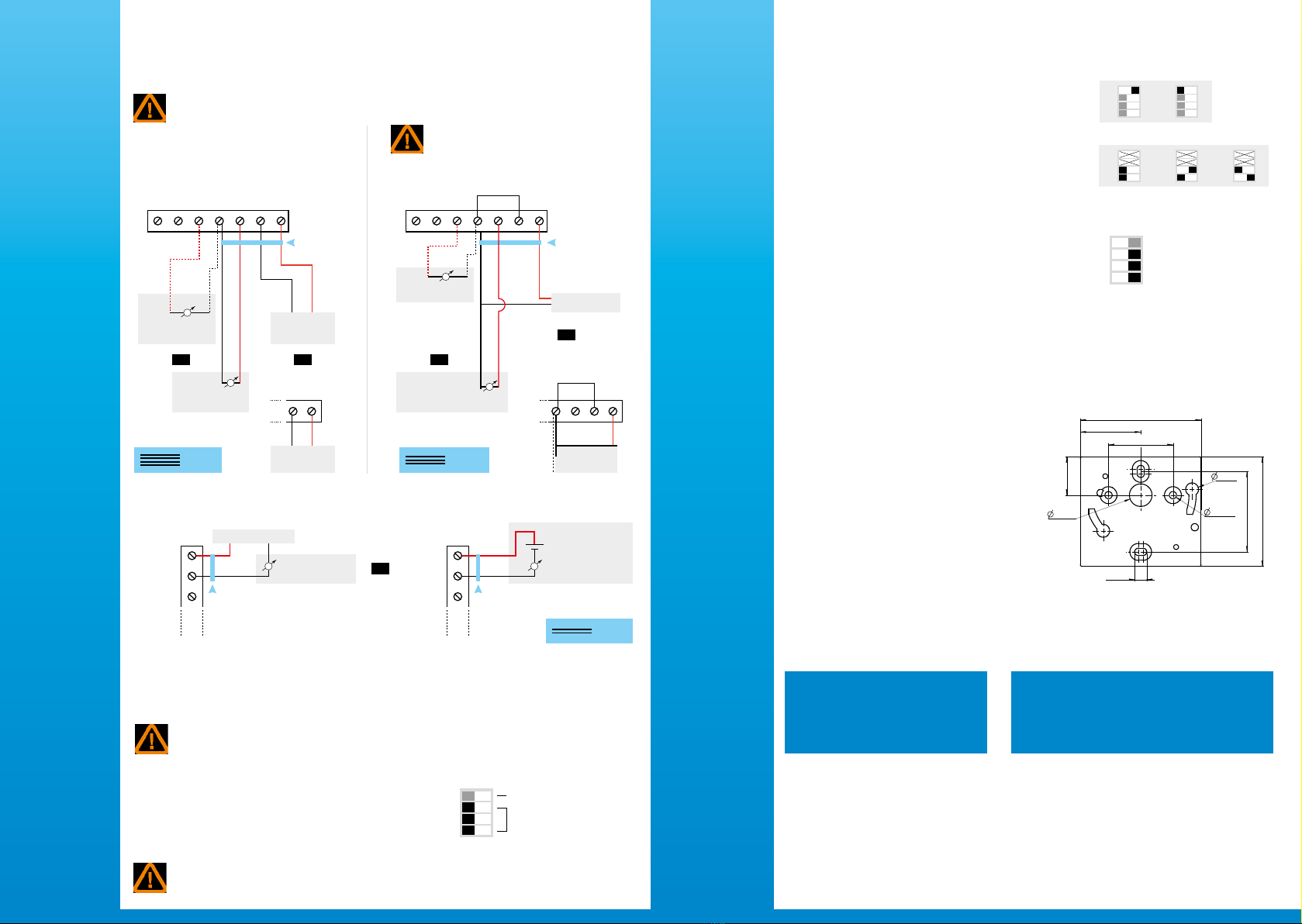
To mount the transmitter, mount the ABS plate on the
wall (drilling: Ø 6 mm, screws and pins are supplied).
Insert the transmitter on the xing plate (see A on
the drawing beside). Rotate the housing in clockwise
direction until you hear a “click” which conrms that
the transmitter is correctly installed.
7.5 mm
8 mm
4.5 mm
40 mm
50 mm
68 mm
75 mm
37.5 mm
23.75 mm
14 mm
A
A
Mounting
Accessories
Maintenance: please avoid any aggressive
solvent. Please protect the transmitter
and its probes from any cleaning product
containing formalin, that may be used for
cleaning rooms or ducts.
Precautions for use: please always use the device
in accordance with its intended use and within
parameters described in the technical features in order
not to compromise the protection ensured by the
device.
Please refer to the data sheet to get more information about available accessories.