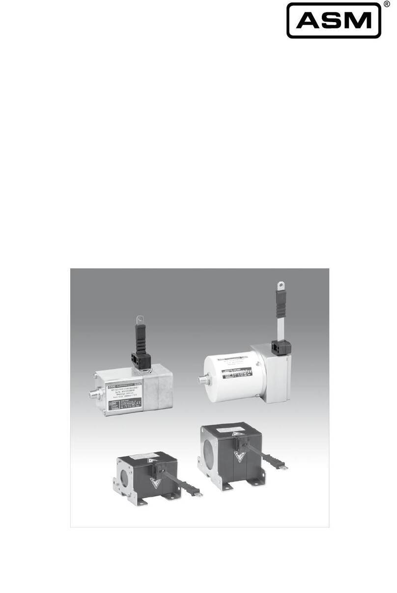
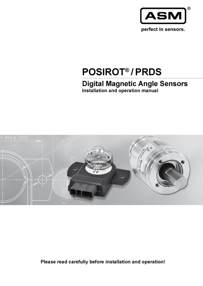
ASM posiwire WST Series User manual

Installation and operation manual EN
Please read carefully before installation and operation!
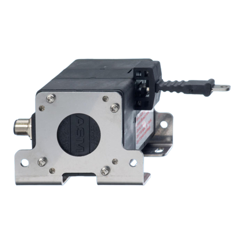
posiwire®WST Series
Combined displacement and inclination sensors

© ASM Automation Sensorik Messtechnik GmbH, 2019
All rights reserved.
Am Bleichbach 18 - 24
85452 Moosinning
Germany

posiwire®
Combined displacement and inclination sensors - WST Series
Version 2.0.0
www.asm-sensor.com
3
1Safety instructions ........................................................................................................4
1.1 Signal words and symbols .............................................................................................................4
1.2 General safety instructions.............................................................................................................5
1.3 Intended use...................................................................................................................................6
2Transport and storage...................................................................................................6
3Installation and initial operation...................................................................................8
3.1 Mechanical installation...................................................................................................................8
3.2 Electrical connection ....................................................................................................................15
3.3 Operating temperature.................................................................................................................17
4Maintenance and disposal..........................................................................................18
4.1 Maintenance and repair ...............................................................................................................18
4.2 Disposal........................................................................................................................................18
5Output specification....................................................................................................19
5.1 Measurement signal and range....................................................................................................19
5.2 Digital interface CANopen............................................................................................................20

posiwire®
Combined displacement and inclination sensors - WST Series
4
Version 2.0.0
www.asm-sensor.com
Pos: 6/ Bedienungsanleit ungen/Module Universal/Ü berschriften/Sicher heitshinweise UE @ 6\mod _1507630884828_78. docx @ 48429 @ 1@ 1
1 Safety instructions
Pos: 7/ Sicherheitshi nweise/Signalwört eru nd Symbole UE @ 1\m od_140014046 7807_78.docx @ 9166 @ 2 @ 1
1.1 Signal words and symbols
Pos: 8/ Sicherheitshin weise/Signalwörter @ 1\mod_1 400240492762_7 8.docx@ 9 385 @ @ 1
WARNING, Risk of Injury:
Indicates a potentially hazardous situation, which, if not avoided, can result in serious
injury or property damage.
WARNING, Risk of Personal Injury or Death:
Indicates a situation that can result in serious personal injury or death if not properly
avoided.
WARNING, Risk of Personal Injury or Death:
Indicates a situation that can result in moderate personal injury or death if not properly
avoided.
WARNING, Risk of Personal Injury:
Indicates a situation that can result in minor personal injury if not properly avoided.
WARNING, Risk of Property Damage:
Indicates a situation that can result in minor to major property damage if not properly
avoided.
Product liability
•Disregarding the following instructions may result in malfunction, damage to property and personal injury
and releases the manufacturer from product liability.
Safety regulations
•National safety regulations must be observed!
Pos: 9/ ######### ##S eitenumbruch ## ############## ############## ##### @ 0\mod_135 3584168894_0. docx@ 336 @ @ 1

posiwire®
Combined displacement and inclination sensors - WST Series
Version 2.0.0
www.asm-sensor.com
5
Pos: 10 /Sicherheitshinweis e/Allg_Sicherheitshi nweiseU E @ 0\mod_13853 98033298_78.doc x@ 261 0@ 2 @ 1
1.2 General safety instructions
Pos: 11 /Sicherheitshinweis e/Sicherheitshin weise_WS @ 8\mod_1566 891570186_78.docx @ 6751 5@ @ 1
Danger of injury to the operator or damage to the property
•Connection to power supply must be performed in accordance with safety
instructions for electrical facilities and performed only by qualified personnel.
•Any alteration, reconstruction or extension of the sensor is not allowed!
•The sensor must be operated only within values specified in the datasheet.
•The danger of personal injury and danger of property damage due to a
malfunction of the sensor in machines or systems must be excluded by
additional safety measures.
•In safety-relevant applications, additional facilities must be provided for
maintaining safety and preventing damage.
•Check whether the protection class of the sensor is suitable for the application.
Risk of crushing and cutting injury due to pre-tensioned spring being released
from housing when opened!
•Do not open the sensor.
Risk of cutting injury due to uncontrolled retraction of the cable
•Do not damage the measuring cable!
•Do not let the measuring cable and the cable fixing spring back uncontrolled!
•Do not exceed the maximum cable extension range!
•Do not bend the measuring cable!
•Do not let the measuring cable be dragged on objects!
Mechanical damage or destruction of the sensor
•Avoid impact and shock to the sensor.
•Do not allow the measuring cable to spring back uncontrolled.
•Do not pull out the measuring cable beyond the range of the sensor.
Malfunction due to the accumulation of dirt on the measuring cable
•Do not oil or lubricate the measuring cable.
Pos: 12 /######## ### Seitenumbruch #### ############## ############# #### @ 0\mod_13 53584168894_0.d ocx @ 336 @ @ 1

posiwire®
Combined displacement and inclination sensors - WST Series
6
Version 2.0.0
www.asm-sensor.com
Pos: 13 /Sicherheits hinweise/Bestimmu ngsgemäße Verwen dung/Bestimmungsg emäße Verwen dungU E @ 1\mod_1 400142179648_ 78.docx @ 9192 @ 2 @ 1
1.3 Intended use
Pos: 14 /Bedienungs anleitungen/Posi wire/WST/Bestimmu ngsgemäße Verwe ndung WST @ 7\m od_1527592073497 _78.docx @ 56185 @ @ 1
posiwire®Cable Extension Position Sensors with an integrated inclinometer are used to measure both linear
and inclination position at the same time. Both output parameters –linear position and inclination –are
independent of each other. For determining measuring range, environmental compatibility and connection
data of the sensor, please note the data sheet. Use the sensor as intended by operating within its specified
technical data and ambient conditions.
The installation and operating instructions supplied with the unit must be respected. All maintenance and
service work must be carried out. The data sheet of the respective sensor is part of this instruction manual. If
yet not available, it may be requested by stating the respective model number.
The sensor must not be improperly mounted, operated or serviced. In addition, operation of the sensor in
faulty condition is prohibited.
Pos: 15 /Bedienungs anleitungen/Posi wire/Transport und Lag erung @ 6\mod_1 508768821175_7 8.docx @ 49055 @ 1 @ 1
2 Transport and storage
Risk of damage to the measuring cable or cable fixing
•Do not lift the sensor by the cable or cable attachment.
Observe storage and transport temperatures according to the temperatures specified in the data sheet.
Max. rel. humidity 60%, dew condensation must be prevented at all times.
The device must be secured against slipping and tipping during transport.
Pos: 16 /Bedienungs anleitungen/Posi wire/Lieferumf ang @ 2\mod_1415609 118551_78.doc x@ 16 784 @ @ 1
Unpacking
Do not unpack sensor by pulling cable or cable clip.
Shipment damages
Check sensor immediately for shipment damage. In case of any damage, please contact your supplier.

posiwire®
Combined displacement and inclination sensors - WST Series
Version 2.0.0
www.asm-sensor.com
7
Removing kink protection / Shipment protection
The kink protection prevents the cable fixing from buckling and damaging the cable. Remove in the direction
of the cable.
1. 2.
Transport protection (for some sensor models) prevents the measuring cable from being extracted before
mounting the sensor. Only remove immediately before mounting:
1. Carefully cut the crimped, short wire end directly at the sensor housing, without applying any axial force
to the wire
2. Pull the wire out of the case at the loop
For further transport, use the original packaging (if available) to avoid transport damage.
Shipment content
•Sensor
•Installation and operation manual
Pos: 17 /######## ### Seitenumbruch #### ############## ############# #### @ 0\mod_13 53584168894_0.d ocx @ 336 @ @ 1

posiwire®
Combined displacement and inclination sensors - WST Series
8
Version 2.0.0
www.asm-sensor.com
Pos: 18 /Bedienungs anleitungen/Mo duleU niversal/Überschrift en/Montage, In betriebnahme UE @ 4\ mod_149147469 4256_78.doc x@ 38 324 @ 1 @1
3 Installation and initial operation
Pos: 19 /Bedienungsanl eitungen/Posiwire/Geg enstecker_WS @ 5\mod_ 1499239358285_78. docx @ 44215 @ @ 1
Mating connectors
Delivery does not include female connectors for electrical connection.
Appropriate mating connectors and preassembled connecting cables are available on request.
Pos: 20 /Bedienungsanl eitungen/Posiwire/M ontage_man @ 3\mod_1 458041468522_78.doc x@ 232 41@ 2 @ 1
3.1 Mechanical installation
Risk of injury from touching the moving measuring cable or moving parts
during operation
•Operate the sensor only with a suitable protective device (e.g. cable cover) to
prevent injury!
Choice of installation position
•Select a protected installation position for the measuring cable.
This prevents damage of the measuring cable.
•Preferably mount the sensor with the cable outlet pointing downwards.
This prevents liquids from entering through the cable outlet.
•Screw the sensor onto a flat surface or provide a three-point mounting.
This avoids distortion and damage to the sensor.
•In harsh environments provide protection for the measuring cable.

posiwire®
Combined displacement and inclination sensors - WST Series
Version 2.0.0
www.asm-sensor.com
9
Cable travel should only be axial to the cable outlet - no misalignment is
allowed
•Cable misalignment shortens service life of sensor and causes error in
measurement. Warranty will not be granted for damage caused by misalignment.
correct incorrect
Sensor with
horizontal extension
Sensor with vertical
extension
•If the measuring cable cannot be extended in the axial direction of the cable
outlet opening due to the measuring task, the SR2 cable pulley must be used to
redirect the cable.
•For special applications, extension cables with cable clips attached on both ends
are available.
Fixing the sensor
Depending upon the sensor model, holes in the base plate, threads, mounting brackets or T-slots in the
sensor housing enable attachment of the sensor. Required dimensions are listed in the data sheet.
Mount the sensor on flat surface.
Use flat washers and/or thread locker if necessary.
The torques of the fixing screws depend on the material used (see p.12).

posiwire®
Combined displacement and inclination sensors - WST Series
10
Version 2.0.0
www.asm-sensor.com
Cable attachment device
The cable clip can be fastened as follows:
•M4 cable connection in cable outlet direction
The M4 connection is mounted with a
through hole, two washers and a M4
nut.
Do not rotate the M4 connection
during assembly, otherwise the
measuring cable will be twisted!
•Cable clip with Allen screw M5: standard fixing.
•Cable clip with attachment head (accessory GK1: metal, GK2: plastic): fast cable attachment, easy to
remove
•Cable clip with magnetic clamp (accessory MAG1): with this device the sensor can be easily used at
several measuring points with ferromagnetic surface.

posiwire®
Combined displacement and inclination sensors - WST Series
Version 2.0.0
www.asm-sensor.com
11
Cable clip attachment
The cable clip (see drawing above) can be opened for easy attachment of the measuring cable. If possible,
fasten cable fixing with cable in retracted position.
Mounting aid for adverse installation conditions
For example, fit a mounting loop and put it around your wrist. Do not remove the mounting loop until after
final installation.
Pos: 21 /######## ### Seitenumbruch #### ############## ############# #### @ 0\mod_13 53584168894_0.d ocx @ 336 @ @ 1
Danger of cutting injuries due to cable clips during cable connection
•Before connecting the cable clip into the fixture read the mounting instructions.

posiwire®
Combined displacement and inclination sensors - WST Series
12
Version 2.0.0
www.asm-sensor.com
Pos: 22 /Bedienungs anleitungen/Posi wire/WST/Anzugs momente WST61_W ST85 @ 7\mod_ 1527592407138_78. docx @ 56195 @ @ 1
Fixing screws
WST61, WST85
Model
Screw
Screw
material
Torque
[Nm]
WST61 (oval hole)
M5
A2
2.0
WST85
M6
A2
4.0
WST85 (oval hole)
M6
A2
3.0
Pos: 23 /Bedienungs anleitungen/Posi wire/WST/Anzugs momente WST21 @ 7 \mod_1527592 501197_78.docx @ 56 200 @ @ 1
WST21
Model
Screw
Screw
material
Torque [Nm]
WST21
M5
A2
2.5
Pos: 24 /######## ### Seitenumbruch #### ############## ############# #### @ 0\mod_13 53584168894_0.d ocx @ 336 @ @ 1

posiwire®
Combined displacement and inclination sensors - WST Series
Version 2.0.0
www.asm-sensor.com
13
Pos: 25 /Bedienungsanl eitungen/Posiwire/W ST/Kennlinie_WST2 1@ 8\ mod_1569320595 958_78.docx @ 68008 @ @ 1
Mounting options for inclination measurement for WST21 sensor
For CAN output, the mounting option can be set by the user via software.
Sensor position as shown equals 0°.
WST21
Mounting option 1
Mounting option 2
Mounting option 3
Output signal
Pos: 26 /Bedienungsanl eitungen/Posiwire/W ST/Kennlinie_WST6 1_85@ 8 \mod_1569316 073408_78.docx @ 67980 @ @ 1

posiwire®
Combined displacement and inclination sensors - WST Series
14
Version 2.0.0
www.asm-sensor.com
Mounting options for inclination measurement for WST61 / WST85 sensors
For CAN output, the mounting option can be set by the user via software.
Sensor position as shown equals 0°.
WST61 / WST85
Mounting option 1
Mounting option 2
Mounting option 3
Output signal
Pos: 27 /######## ### Seitenumbruch # ############## ############## ###### @ 0\mod_13 53584168894_0.d ocx @ 336 @ @ 1
Pos: 28 /Bedienungsanl eitungen/Posiwire/W ST/Elektrischer Anschluss_ WST_WBT @ 7\mod_ 1532340836982_ 78.docx @ 57767@ 2 @ 1

posiwire®
Combined displacement and inclination sensors - WST Series
Version 2.0.0
www.asm-sensor.com
15
3.2 Electrical connection
Damage or destruction of the sensor due to excessive operating voltage or
mounting error
•The applied operating voltage must not exceed the value specified in the data
sheet.
•Operate the sensor only within the limits specified in the data sheet.
•Connecting to the power supply only by qualified personnel and in accordance with
the applicable safety regulations for electrical equipment.
•Do not connect or disconnect the sensor under voltage!
Corrosion in the sensor due to moisture penetration
•Use the sensor only according to protection class.
•The mating connector should have the same protection class as the sensor,
otherwise the lower protection class of the mating connector is valid.
•Avoid crossing the dew point.
•Cable outputs must be installed in such a way that no moisture can get into the
cable.
•The protection class of sensors with connector output is valid only if the electrical
plug is connected!
Damage of the sensor cable due to mechanical stress
•Do not twist the M12 connector insert.
•It is important that the knurled nuts on the connectors are tightened to the correct
torque for each different size of the connector:
•M12-ASM connectors / couplings: 1.0 Nm
•connectors / couplings of other manufacturers: according to manufacturer
instruction.
•Use a torque wrench.
•Do not strain the connection cable.
•A separate strain relief is recommended.
Connector Pin assignment
According to the definitions of the output types contained in the appendix. Observe different color code for
pre-assembled accessory cables. See catalog information for accessories.
Supply voltage
See specification in the data sheet of the sensor. The maximum operating voltage must not be exceeded.
Pos: 29 /######## ### Seitenumbruch #### ############## ############# #### @ 0\mod_13 53584168894_0.d ocx @ 336 @ @ 1

posiwire®
Combined displacement and inclination sensors - WST Series
16
Version 2.0.0
www.asm-sensor.com
Pos: 30 /Bedienungsanl eitungen/Module Uni versal/M ontageS ensorkabel @ 6\mod_ 1519651235286_ 78.docx @ 52835 @ @ 1
Installation of the sensor supply cable
incorrect
correct
Admissible bending radius of the
cable must be observed:
R ~ 5 x D
R ~ 10 x D (underwater cable)
Length compensation for the
cable must be observed
A separate cord grip for cable
strain relief is recommended
Observe cable routing in case of
splashing water, water
condensation and humidity
Pos: 31 /######## ### Seitenumbruch #### ############## ############# #### @ 0\mod_13 53584168894_0.d ocx @ 336 @ @ 1

posiwire®
Combined displacement and inclination sensors - WST Series
Version 2.0.0
www.asm-sensor.com
17
Pos: 32 /Bedienungsanl eitungen/Posiwire/W S_EMV @ 6\mod_150764 9582488_78.docx @ 48479 @ @ 1
Electromagnetic Compatibility (EMC)
Electromagnetic compatibility of posiwire®Cable Extension Position Sensors is influenced by the sensor
wiring.
Pos: 33 /Bedienungsanl eitungen/Posiwire/W ST/Arbeitstemperatur _Übersicht_WST @ 7\m od_1527592741116_ 78.docx @ 56211 @ 2 @ 1
3.3 Operating temperature
The operating temperature of a sensor depends on the sensor type and encoder technology used:
posiwire® WST61
posiwire® WST85
posiwire® WST21
-40 … +85°C
-40 … +85°C
-40 … +85°C
Pos: 34 /######## ### Seitenumbruch #### ############## ############# #### @ 0\mod_13 53584168894_0.d ocx @ 336 @ @ 1
Possible malfunction of the sensor when used in systems with highly
electromagnetic interference emitting components such as frequency inverters
Recommended wiring:
•Use single shielded sensor cable with twisted pair conductors for power supply
and signal output.
•Connect the cable shield to ground on one side of the control cabinet. Connect
the shield connection over a large area using cable clamps before or at the cable
entry into the control cabinet. When preassembled cables are delivered, the
screen is not connected to the housing on the sensor side.
•Do not install sensor cables close to power conductors such as motor or
contactor control cables (use separate cable ducts for signal and power cables).
•Install the cables in metal cable ducts connected to ground.

posiwire®
Combined displacement and inclination sensors - WST Series
18
Version 2.0.0
www.asm-sensor.com
Pos: 35 /Bedienungs anleitungen/Mo duleU niversal/Überschrift en/Instandh altung und Entsorgung U E@ 6\ mod_1507630731 526_78.docx @ 48417 @ 1 @ 1
4 Maintenance and disposal
Pos: 36 /Bedienungs anleitungen/Posi wire/WST/WST_Ins tandhaltung @ 7\ mod_1527595612 731_78.docx @ 56271 @ 2 @ 1
4.1 Maintenance and repair
Risk of crushing and cutting injury due to pre-tensioned spring being released
from housing when opened!
•Do not open the sensor.
•Due to possible risk of injury by improper handling, we strongly advise against
repair attempts.
Check sensor regularly for possible damage:
Inspection of …
Measures
Integrity of housing
Send damaged sensor to ASM for repair
Integrity of connector, cable
Replace damaged parts resp. send sensor to ASM for repair
Mounting elements
Tighten mounting parts with recommended torque, if applicable use bolt
adhesive
Cable
Damaged cable, spliced or bended cable: send sensor to ASM for
repair
Opening the following sensors will cause damage and void the warranty:
•posiwire® WST61
•posiwire® WST85
•posiwire® WST21
Pos: 37 /Bedienungs anleitungen/Posi wire/WS_Kalibrierung @ 4 \mod_1491 566471251_78. docx@ 3 8399 @ @ 1
Calibration
The recommended calibration interval is 1 year.
Test protocol and traceable calibration certificate (ISO9001 / ISO10012) is available on request.
Pos: 38 /Bedienungsanl eitungen/Posiwire/W S_Entsorgung @ 6\mod_15 07649730932_78. docx @ 48485 @ 2@ 1
4.2 Disposal
Disposal according to applicable government regulations.
Pos: 39 /######## ### Seitenumbruch #### ############## ############# #### @ 0\mod_13 53584168894_0.d ocx @ 336 @ @ 1

posiwire®
Combined displacement and inclination sensors - WST Series
Version 2.0.0
www.asm-sensor.com
19
Pos: 40 /Bedienungs anleitungen/Mo duleU niversal/Überschrift en/Spezifikati ond erA usgangsarten U E @ 6\mod_1507 636478996_78.doc x @4 8453 @ 1 @ 1
5 Output specification
Pos: 41 /Bedienungsanl eitungen/Posiwire/W ST/Messsignal und Messbereich WST @ 7\m od_1527669805463 _78.docx @ 56345 @ 2 @ 1
5.1 Measurement signal and range
Digital absolute
Absolute encoder
Measurement range corresponds to a digitally coded number (resolution eg. 10 steps / mm).
Position
0%
30%
100%
Measurement value
(example)
0 steps
3,000 steps
10,000 steps
Pos: 42 /######## ### Seitenumbruch #### ############## ############# #### @ 0\mod_13 53584168894_0.d ocx @ 336 @ @ 1

posiwire®
Combined displacement and inclination sensors - WST Series
20
Version 2.0.0
www.asm-sensor.com
Pos: 43 /Ausgangs arten/Posiwire/Digital e Schnittstelle CAN openUE @ 7 \mod_152766404 3770_78.docx @ 563 36@ 2 @ 1
5.2 Digital interface CANopen
Pos: 44 /Bedienungsanl eitungen/Posiwire/W ST/CANopen_WST @ 7\m od_1527673374081_ 78.docx @ 56351 @ @ 1
MCANOP, CANOPR
CAN specification
ISO 11898, Basic and Full CAN 2.0 B
Communication profile
CANopen CiA 301 V 4.02, Slave
Encoder profile
Encoder CiA 406 V 3.2
Error Control
Node Guarding, Heartbeat, Emergency
Message
Node ID
Adjustable via LSS or SDO, default: 127
PDO
3 TxPDO, 0 RxPDO, no linking, static
mapping
PDO Modes
Event-/Time triggered, Remote-request, Sync
cyclic/acyclic
SDO
1 Server, 0 Client
CAM
8 cams
Certified
Yes
Transmission rate
50 kBit bis 1 Mbit, adjustable via LSS or
SDO, default: 125 kBit
Bus connection
M12 conncector, 5 pin
Integrated bus terminating
resistor
120Ω adjustable by the customer
Bus, galvanic isolated
no
Specifications
Excitation voltage
8 ... 36 V DC
Excitation current
20 mA typical at 24 V DC
40 mA typical at 12 V DC
80 mA max.
Measuring rate
0.5 kHz
Stability (temperature)
±50 x 10-6/°C f.s. (typical)
Repeatability
1 LSB
Operating temperature
See specification of the respective sensor
Protection
Reverse polarity, short circuit
Dielectric strength
1 kV (V AC, 50 Hz, 1 min.)
EMC
EN 61326-1:2013
This manual suits for next models
4
Table of contents
Other ASM Accessories manuals

ASM
ASM positape WBT Series User manual

ASM
ASM posiwire User manual

ASM
ASM posirot PRAS Series User manual

ASM
ASM POSIROT Series User manual

ASM
ASM PRDS-CANOPR User manual

ASM
ASM posiwire WS10EX User manual

ASM
ASM POSITAPE WB Series User manual

ASM
ASM positilt PTM Series User manual

ASM
ASM posirot PRAS Series User manual

ASM
ASM posirot PRAS Series User manual