Benewake TF350 User manual

TF350 UART/CAN User Manual
INTRODUCTION
Page2 ©Benewake · All rights reserved · Subject to change without notice · 2021-12-06
Described product
Long-range single-point LiDAR: TF350-UART / CAN.
Manufacturer
Benewake (Beijing) Co., Ltd.
Room 3030, Building ZiZhuChuangXin,
No.6 Chuangye Road,
Haidian District,
Beijing, PRC
Legal information
This work is protected by copyright. Any rights derived from the copyright shall be reserved for
Benewake (Beijing). Reproduction of this document or parts of this document is only permissible
within the limits of the legal determination of Copyright Law. Any modification, abridgment or
translation of this document is prohibited without the express written permission of Benewake
(Beijing).
The trademarks stated in this document are the property of their respective owner.
© Benewake (Beijing). All rights reserved.
Original document
This document is an original document of Benewake (Beijing).

TF350 UART/CAN User Manual
INTRODUCTION
Page3 ©Benewake · All rights reserved · Subject to change without notice · 2021-12-06
TABLE OF CONTENTS
1INTRODUCTION...................................................................................................................................... 4
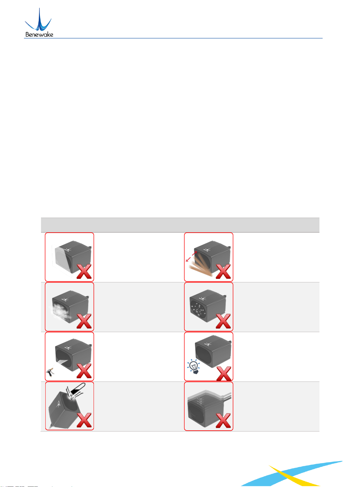
1.1 FAILURE SCENARIOS ................................................................................................................................. 4
1.2 SYMBOLS AND DOCUMENT CONVENTIONS .................................................................................................... 5
2PRODUCT DESCRIPTION ......................................................................................................................... 6
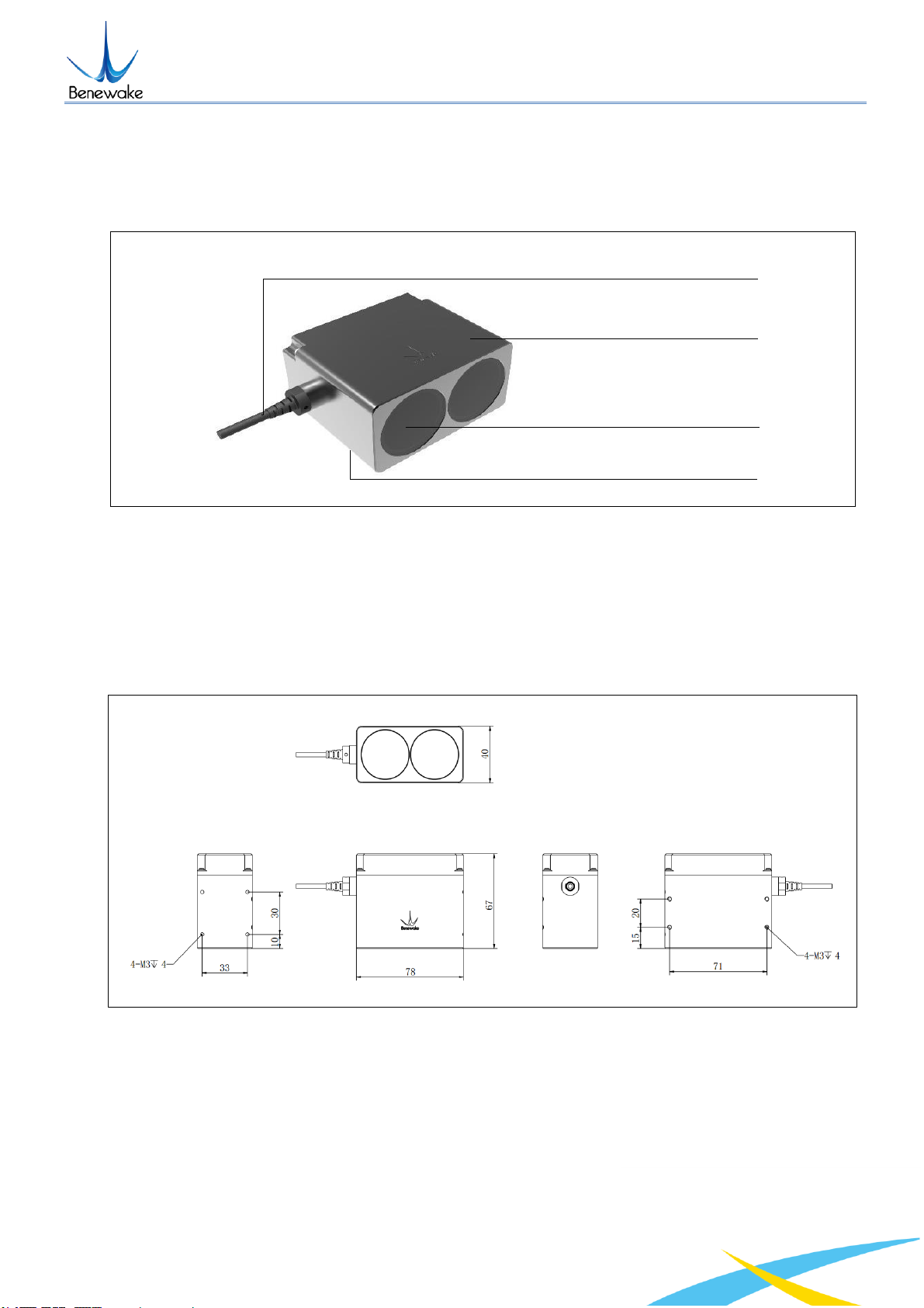
2.1 APPEARANCE OVERVIEW ........................................................................................................................... 6
2.2 DIMENSIONAL DRAWING........................................................................................................................... 6
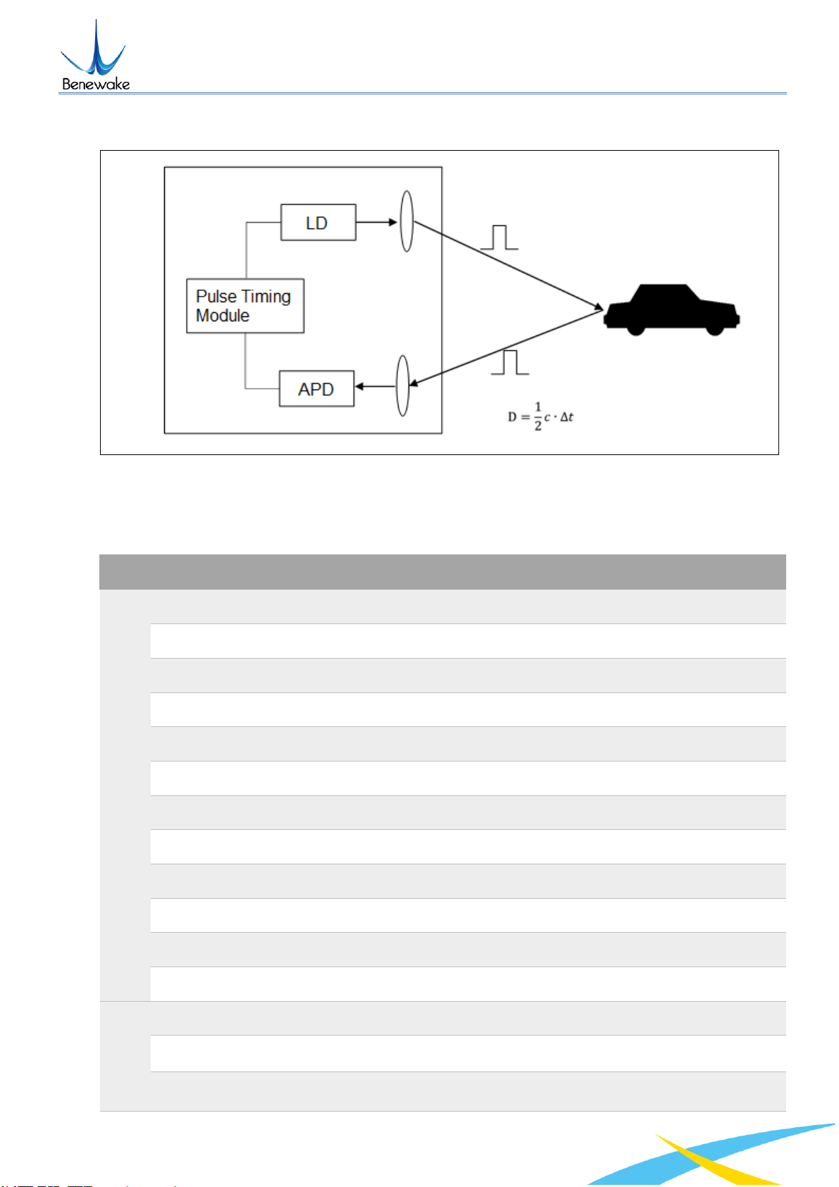
2.3 MEASURING PRINCIPLE ............................................................................................................................. 6
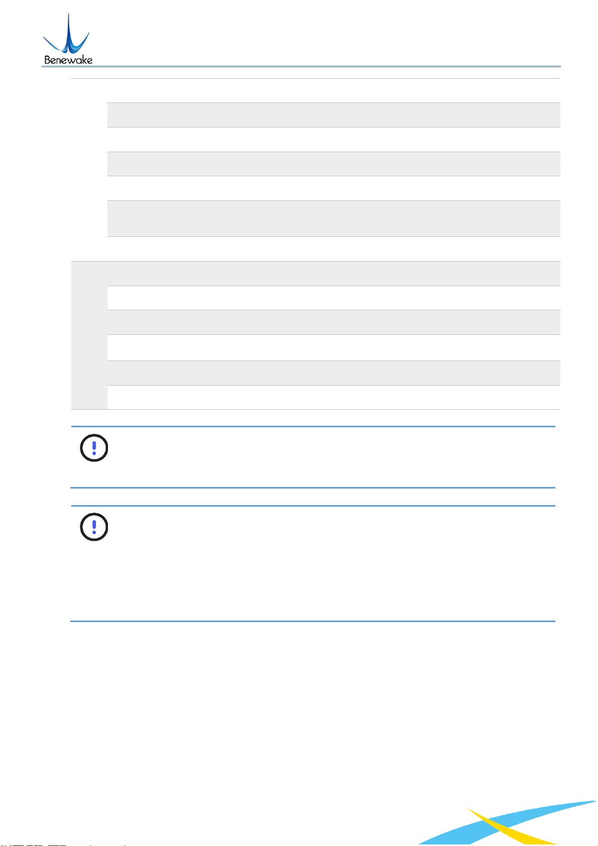
2.4 TECHNICAL SPECIFICATION ......................................................................................................................... 7
2.5 FOV...................................................................................................................................................... 8
3ELECTRICAL INSTALLATION ................................................................................................................... 10
3.1 PIN AND WIRE COLOR ASSIGNMENT........................................................................................................... 10
3.2 WIRE CROSS-SECTIONS ........................................................................................................................... 10
3.3 WIRING UART INTERFACE....................................................................................................................... 11
3.4 WIRING CAN INTERFACE......................................................................................................................... 11
3.5 CAN BUS ............................................................................................................................................. 11
4PROTOCOLS.......................................................................................................................................... 13
4.1 COMMUNICATION PROTOCOL OF UART..................................................................................................... 13
4.2 USER PROTOCOL: UART ......................................................................................................................... 13
4.3 COMMUNICATION PROTOCOL OF CAN....................................................................................................... 14
4.4 USER PROTOCOL: CAN........................................................................................................................... 14
5CUSTOM CONFIGURATION ................................................................................................................... 14
5.1 PROTOCOL DESCRIPTION ......................................................................................................................... 14
5.2 COMMON COMMANDS........................................................................................................................... 15
5.3 COMMAND EDITING............................................................................................................................... 17
6OPTIONAL ACCESSORIES ...................................................................................................................... 17
6.1 SELF-CLEANING MODULE......................................................................................................................... 17
6.2 AIMING BEAM MODULE .......................................................................................................................... 19
6.3 EXTENSION CORD................................................................................................................................... 20
7QUICK START GUIDE ............................................................................................................................. 21
7.1 CONNECTION AND BASIC TEST .................................................................................................................. 21
7.2 TROUBLESHOOTING GUIDE FOR INITIAL TEST................................................................................................ 22
7.3 WORKING MODE ................................................................................................................................... 23
7.4 INFLUENCES OF OBJECT SURFACES ON THE MEASUREMENT.............................................................................. 23
8TROUBLESHOOTING ............................................................................................................................. 26
ATTACHMENT 1: REFLECTIVITY OF DIFFERENT MATERIALS......................................................................... 28

TF350 UART/CAN User Manual
INTRODUCTION
Page4 ©Benewake · All rights reserved · Subject to change without notice · 2021-12-06
1 INTRODUCTION
The Reference Manual is a complement to the Operating Instructions for TF350. The
Operating Instructions for TF350 describes how to set up and configure the interfaces.
The Reference Manual contains detailed information about the interfaces including syntax
and available functionality. It focuses on TF350 specific topics and does not describe the
basic technology behind each interface.
The details of the result output formatting and the contents and syntax of the command
channels are shared by several interfaces. They are described in an appendix valid for all
relevant interfaces.
1.1 Failure scenarios
As a precision optical distance sensor, TF350’s performance is greatly affected by
environment. Certain scenarios will even damage TF350. Each of these failure scenarios
have been tested in real field tests.
Table 1 Failure scenarios of TF350
Scenario
Description
Scenario
Description
Do not cover the laser
window.
Avoid moving objects in the
detection field.
Avoid the presence of
heavy smoke, fog and rain
in the detection field.
Avoid condensation.
Avoid direct exposure to
high pressure cleaning.
Avoid exposure to strong
light source with same
wavelength.
Do not exposure to
corrosive liquids.
Avoid extreme vibrations.

TF350 UART/CAN User Manual
INTRODUCTION
Page5 ©Benewake · All rights reserved · Subject to change without notice · 2021-12-06
Do not use in extremely low
temperature environments.
Do not use in extremely
high temperature
environments.
Avoid exposure to sudden
and extreme temperature
changes.
Avoid direct exposure to
another LiDAR with same
wavelength.
1.2 Symbols and document conventions
The following symbols and conventions are used in this document:
WARNING
Indicates a situation presenting possible danger, which may lead to death or
serious injuries if not prevented.
CAUTION
Indicates a situation presenting possible danger, which may lead to moderate or
minor injuries if not prevented.
NOTICE
Indicates a situation presenting possible danger, which may lead to property
damage if not prevented.
NOTE
Indicates useful tips and recommendations.

TF350 UART/CAN User Manual
PRODUCT DESCRIPTION
Page6 ©Benewake · All rights reserved · Subject to change without notice · 2021-12-06
2 PRODUCT DESCRIPTION
2.1 Appearance overview
Figure 1 Module view of TF350
①6 core cable (70cm), MH1.25-7P-W/B, 7pin
②Laser window (Receiving)
③Laser window (Emitting)
④3mm diameter hole (6mm deep) for mounting (6x)
2.2 Dimensional drawing
Figure 2 Dimensional drawing of TF350 (
①
Front;
②
Top;
③
Bottom; Unit: mm)
2.3 Measuring principle
TF350 is a typical Pulse Time of Flight (PToF) sensor. TF350 emits a narrow pulse laser,
which is collimated by the transmitting lens, which enters the receiving system after being
reflected by the measured target and is focused on the APD detector by the receiving lens.
The time between the transmitted signal and the received signal is calculated through the
circuit amplification and filtering, and the distance between TF350 and the measured target
④
②
①
③
①
②
③

TF350 UART/CAN User Manual
PRODUCT DESCRIPTION
Page7 ©Benewake · All rights reserved · Subject to change without notice · 2021-12-06
can be calculated through the speed of light.
Figure 3 Pulsed time of flight (PToF)
2.4 Technical specification
Table 2 Technical specifications of TF350
Parameters
Minimum
Typical
Maximum
Performance
Range (@90% reflectivity, 0klux)
0.2m
350m
Range (@10% reflectivity, 0klux)
0.2m
110m
Range (@90% reflectivity, 100klux)
0.2m
300m
Range (@10% reflectivity, 100klux)
0.2m
100m
Accuracy
±10cm (<10m), 1% ≥10m)
Distance resolution
1cm
Frame rate
1Hz
100Hz
1000Hz
Repeatability
1σ: <3cm
Light source
LD
Central wavelength
905nm
Photobiological safety
Class1(EN60825)
FoV
0.35°
Environment
Ambient light immunity
100Klux
Operation temperature
-25℃
60℃
Enclosure rating
IP67

TF350 UART/CAN User Manual
PRODUCT DESCRIPTION
Page8 ©Benewake · All rights reserved · Subject to change without notice · 2021-12-06
Connections
Supply voltage
5V DC
24V DC
Average current
≤150mA @ 5V, ≤80mA @ 12V, ≤50mA @ 24V
Power consumption
≤1W
Overvoltage protection
300V
Polarity protection
200V
Communication interface level
LVTTL
(3.3V)
Communication interface
RS-485 / RS-232
Others
Dimension
78mm*67mm*40mm(L*W*H)
Housing
Aluminum alloy
Optical window
Infrared optical glass (HWB760)
Storage temperature
-40℃
85℃
Weight
222g ± 3g
Cable length
70cm
NOTICE
The basic technical specifications, like accuracy and repeatability, are measured
with white background board (90% reflectivity) at 0klux condition.
NOTICE
Only the frame rate satisfying the following formula is supported.
If a value which does not satisfy this formula is set, TF350 will set its frame rate
to 100Hz. The normal frame rate is under 1kHz, but the maximum frame rate can
reach as much as 7kHz. Please contact us if you need higher frame rate.
2.5 FoV
The field-of-view, FoV, is the angle covered by the LiDAR sensor. The horizontal FoV of
TF350 is about 0.35° and the vertical FoV of TF350 is approx. 0.1°.

TF350 UART/CAN User Manual
PRODUCT DESCRIPTION
Page9 ©Benewake · All rights reserved · Subject to change without notice · 2021-12-06
NOTICE
0.35° and 0.1° are theoretic values. Because the manufacturing error and the
installing error exist, there is divergence between each TF350’s actual FoV and
its theoretic values.
Figure 5 Spot size of TF350 at different ranges
0.00
50.00
100.00
150.00
200.00
250.00
050 100 150 200 250 300 350
Spot Size (cm)
Range (m)
Length of the detecting spot.
Divergence 0.35 degree.
Width of the detecing spot.
Divergence 0.15 degree.
Figure 4 FoV of TF350. Horizontal divergence 0.35°, vertical divergence 0.1°

TF350 UART/CAN User Manual
ELECTRICAL INSTALLATION
Page10 ©Benewake · All rights reserved · Subject to change without notice · 2021-12-06
3 ELECTRICAL INSTALLATION
3.1 Pin and wire color assignment
TF’s cable has six 26 AWG wires. The connector is Molex SD-51021-007 1.25 W/B-7Pin.
Table 3 Pin assignment on 7-pin male connector
Pin
Color
Signal
Function
1
Red
DC 5~24V
Supply Voltage
2
White
CAN_L
CAN-BUS Low
3
Green
CAN_H
CAN-BUS High
4
N/A
N/A
N/A
5
Blue
UART RxD
UART Receive
6
Brown
UART TxD
UART Transmit
3.2 Wire cross-sections
CAUTION
If you use flexible connecting cables with stranded wire, then you must not use
ferrules when connecting the wires to the terminals on TF350.
Wire all connections with copper cables!
Use the following wire cross-sections:
⚫supply voltage at least 0.13 mm² (approx. 26 AWG), if local power supply in the immediate
vicinity.
⚫supply voltage at least 0.21 mm² (approx. 24 AWG) at maximum length of 2m (6.562 ft),
if the connection is made to an existing 24 V DC supply.
⚫switching outputs minimum 0.13 mm² (approx. 26 AWG), maximum cable length 2m
(6.562 ft) with 0.21 mm² (approx. 24AWG).
⚫data interface minimum 0.21mm² (approx. 24 AWG).
Figure 6 Male connector, Molex SD-51021-007 1.25 W/B-7Pin

TF350 UART/CAN User Manual
ELECTRICAL INSTALLATION
Page11 ©Benewake · All rights reserved · Subject to change without notice · 2021-12-06
3.3 Wiring UART interface
A screened cable is required for the wiring of the UART interface.
Pay attention to max. cable length as per section Wire cross-sections.
NOTICE
To connect two devices for UART serial communication, the transmitter’s TXD
should connect to the receiver’s RXD and the receiver’s TXD should connect to
the transmitter’s RXD.
3.4 Wiring CAN interface
To wire the CAN interface a screened “twisted-pair” cable is required.
Pay attention to max. cable length as per section Wire cross-sections.
3.5 CAN bus
Unlike a traditional network such as USB or Ethernet, CAN does not send large blocks of
data point-to-point from one node to another under the supervision of a central bus master.
Once CAN basics such as message format, message identifiers, and bit-wise arbitration - a
Figure 8 Wiring of the CAN interface
Figure 7 Wiring of the UART interface

TF350 UART/CAN User Manual
ELECTRICAL INSTALLATION
Page12 ©Benewake · All rights reserved · Subject to change without notice · 2021-12-06
major benefit of the CAN signaling scheme are explained, a CAN bus implementation is
examined, typical waveforms presented, and transceiver features examined.
Figure 9 CAN networking of TF350
The High-Speed ISO 11898 Standard specifications are given for a maximum signaling rate
of 1 Mbps with a bus length of 40 m with a maximum of 30 nodes. It also recommends a
maximum unterminated stub length of 0.3 m. The cable is specified to be a shielded or
unshielded twisted-pair with a 120-Ω characteristic impedance (Zo).
For CAN bus connection, there are two resistances need to be removed from TF350. See
Figure 10 Resistances needed to be removed from board for CAN Bus for the location of
Resistance #2 and #3.
Figure 10 Resistances needed to be removed from board for CAN Bus
WARNING
Removing resistance R2 and R3 needs to disassemble TF350. To avoid
irreversible damage to TF350, please contact our technical support engineers for
detailed instructions.
R2
R3

TF350 UART/CAN User Manual
PROTOCOLS
Page13 ©Benewake · All rights reserved · Subject to change without notice · 2021-12-06
4 PROTOCOLS
The standard version of TF350 supports two communication interfaces, UART and CAN.
The default interface is UART. These two interfaces cannot work simultaneously. The
communication interface can be switched by certain command.
4.1 Communication protocol of UART
Table 4 Characteristics of UART
Character
Value
Configurability
Baud rate
115200
Configurable
Data bit
8
Non-configurable
Stop bit
1
Non-configurable
Parity
None
Non-configurable
4.2 User protocol: UART
A standard data frame consists of 9 bytes of hexadecimal numbers, which contains distance
and signal strength.
NOTE
Strength value is between 0 and 3500. Threshold of strength is 40, when strength
is lower than 40, distance will output maximum value. When strength is between
40 and 1200, distance is more reliable. When detecting a high reflectivity object,
signal strength will be over 1500.
Figure 11 Data communication: User protocol frame format of UART
Each data frame consists of 9 bytes hexadecimal data which contains the distance and
signal strength.

TF350 UART/CAN User Manual
CUSTOM CONFIGURATION
Page14 ©Benewake · All rights reserved · Subject to change without notice · 2021-12-06
NOTE
Strength value is between 0 and 3500. Threshold of strength is 40, when strength
is lower than 40, distance will output maximum value. When strength is between
40 and 1200, distance is more reliable. When detecting a high reflectivity object,
signal strength will be over 1500.
4.3 Communication protocol of CAN
The CAN interface supports data transmissions between 10Bit/s and 1Mbit/s. The maximum
cable length is 2m (6.562ft).
Table 5 Characteristics of CAN
Character
Value
Configurability
Baud rate
1MBit/s
Configurable
Receiving ID
0x3003
Configurable
Transmitting ID
0x03
Configurable
Message frames
Standard Frame
Extended Frame
Configurable
4.4 User Protocol: CAN
Figure 12 Data communication: User protocol frame format of CAN
5 CUSTOM CONFIGURATION
5.1 Protocol description
To meet the need of different customers, TF350 released several configuration parameters.
These parameters, such as data format, frame rate, could be modified by certain command.
All the parameters will be stored in flash after configured successfully and customers don’t
need to configure again when restart.

TF350 UART/CAN User Manual
CUSTOM CONFIGURATION
Page15 ©Benewake · All rights reserved · Subject to change without notice · 2021-12-06
Table 6 Description of TF350 command protocol
Byte
Definition
Description
Byte 0
Header
Fixed to 0x5A
Byte 1
Len
The length of the entire instruction frame (unit: Byte)
Byte 2
ID
Identifies the function of each instruction
Byte 3~Byte N-2
Payload
Different meanings and lengths in different ID instruction frames
Byte N-1
Check sum
The low 8 bits of the Len-1-byte data
5.2 Common commands
Table 7 List of TF350’s common commands
Description
Command
Response
Remark
Default
setting
Obtain firmware
version
5A 04 01 5F
5A 07 01 VA VB VC
SU
The version number
VC.B.A
/
System reset
5A 04 02 60
5A 05 02 00 61
/
/
Modify frame
rate
5A 06 03 LL HH SU
Same as command
LL: lower 8 bits
HH: higher 8 bits
100Hz
Output control
On: 5A 05 07 01 67
Off: 5A 05 07 00 66
Same as command
/
Enabled
Enable
command
triggering mode
5A 05 07 00 66
Same as command
/
Disabled
Trigger
measurement
5A 04 04 62
Data frame
Only works in
command triggering
mode
/
Change baud
rate
5A 08 06 H1 H2 H3
H4 SU
Same as command
See 0
Command editing
115200
Restore default
settings
5A 04 10 6E
5A 05 10 00 6F
/
/
Save settings
5A 04 11 6F
5A 05 11 00 70
/
/
Over range
threshold
setting
5A 06 4F LL HH SU
5A 05 4F 00 AE
Unit: cm
LL: lower 8 bits
HH: higher 8 bits
35000
Switch
communication
interface
UART: 5A 05 45 01
A5
CAN: 5A 05 45 02 A6
5A 05 45 00 A4
/
UART

TF350 UART/CAN User Manual
CUSTOM CONFIGURATION
Page16 ©Benewake · All rights reserved · Subject to change without notice · 2021-12-06
Modify CAN
arbitration ID
5A 08 50 H1 H2 H3 H4
SU
5A 05 50 00 AF
ID = (H4<<24)
+(H3<<16) +(H2<< 8)
+H1
0x03
Modify CAN
5A 08 51 H1 H2 H3 H4
SU
5A 05 51 00 B0
ID=(H4<<24)
+(H3<<16) +(H2<< 8)
+H1
0x3003
Modify baud
rate of CAN
5A 08 52 H1 H2 H3 H4
SU
5A 05 52 00 B1
Baud rate=(H4<<24)
+(H3<<16) +(H2<<8)
+H1
1Mbits/s
Set frame type
of CAN
Standard frame: 5A
05 5D 00 BC
Extension frame: 5A
05 5D 01 BD
5A 05 5D 00 BC
/
Standard
frame
Enable UAVCAN
5A 05 77 MD SU
5A 05 77 00 D6
MD:filter switch
0x00:filter off
0x01:filter on
/
Offset setting
5A 06 69 LL HH SU
5A 05 69 00 C8
Unit: cm
LL: lower 8 bits
HH: higher 8 bits
0
Low-power
consumption
mode
On: 5A 05 83 01 E3
Off: 5A 05 83 00 E2
Same as command
/
Off
WARNING
Do not send the command that is not in the list above.
NOTE
Baud rate of UART can be set to 9600, 14400, 19200, 38400, 56000, 57600,
115200, 128000, 230400, 256000, 460800, 500000, 512000, 600000, 750000,
and 921600. If other value were set, TF350 will set it to 115200.
NOTE
Offset configuration can be used for secondary calibration of distance, for
example, when distance is 195cm and you want LiDAR outputs 200cm, you can
set offset value to 5cm.

TF350 UART/CAN User Manual
OPTIONAL ACCESSORIES
Page17 ©Benewake · All rights reserved · Subject to change without notice · 2021-12-06
5.3 Command editing
This section describes the Command Channel of TF350 which is used to read and set
TF350’s working parameters. The command channel is available via all the interfaces.
A standard TF350 command consists of frame header, command length, command ID,
parameters, and checksum. Follow these steps to generate a command:
⚫Choose the right command ID and confirm its length
⚫Convert parameter from the decimal value to hexadecimal value
⚫Fill the hexadecimal parameter into the command
⚫Calculate the checksum and fill its low 8-bits into the command
For example, changing the baud rate to 460800. Firstly, choose the ID of changing frame
rate, which is 0x06. Secondly, change 460800 (decimal number) to hexadecimal number,
which is 0x00 07 08 00. Thirdly, fill the parameter into the command, like 5A 08 06 00 08 07
00 SUM. Finally calculate the sum of the first 7bytes and take its low 8bits, we will have the
complete command, 5A 08 06 00 08 07 00 77.
Figure 13 Command syntax of TF350
6 OPTIONAL ACCESSORIES
NOTE
The following accessories are not standard accessories, please contact relevant
sales or technical personnel if necessary.
6.1 Self-cleaning module
In some outdoor scenes, dust adhering to the TF350’s window will affect the performance of
the TF350. We’ve designed the following self-cleaning module that can automatically clean
Header
Length
ID
Hexadecimal parameters
Checksum
Fixed: 0x5A
Length of the command
(Number of bytes)
ID of the command
Hexadecimal parameters
Little-endian mode
Lower 8 bits of the sum of
previous bytes

TF350 UART/CAN User Manual
OPTIONAL ACCESSORIES
Page18 ©Benewake · All rights reserved · Subject to change without notice · 2021-12-06
the TF350’s window regularly. The module drives the rocker arm and wiper with the steering
gear to clean the TF350 window regularly.
Figure 14 Dimension drawing of self-cleaning module
The self-cleaning module is fixed with TF350 through the metal base, its power supply and
communication are completely independent from TF350.
Figure 15 Wiring of self-cleaning module
①
②
③

TF350 UART/CAN User Manual
OPTIONAL ACCESSORIES
Page19 ©Benewake · All rights reserved · Subject to change without notice · 2021-12-06
Table 8 Pin assignment of steering gear
Pin
Color
Signal
Function
1
Black/Brown
GND
Ground
2
Red
DC +5V
Supply voltage
3
Yellow
PWM
Signal channel
NOTE
The working pattern of steering gear is configurable, please contact us for detailed
information.
6.2 Aiming beam module
The wavelength of TF350’s detecting light is 905nm, which is invisible light. We’ve designed
an aiming beam module to assist the installation.
Figure 16 Sketch map of Aiming beam module

TF350 UART/CAN User Manual
OPTIONAL ACCESSORIES
Page20 ©Benewake · All rights reserved · Subject to change without notice · 2021-12-06
Figure 17 Installation of Aiming beam module
NOTE
The aiming beam powered by button battery is a low-power laser. Its indoor
effective range is approximate 150 meters, and its outdoor effective range is about
30 meters.
6.3 Extension cord
For testing purposes, we prepared an extension Dupont cord. See Figure 18 Extension cord
for test for detailed information.
Figure 18 Extension cord for test
NOTE
This extension cord is free, but it’s not a standard accessory. Please contact us if
needed.
Other manuals for TF350
1
Table of contents
Other Benewake Accessories manuals

Benewake
Benewake TFmini-i User manual

Benewake
Benewake TF350 User manual

Benewake
Benewake TF03 User manual

Benewake
Benewake TF02-Pro-W-485 User manual

Benewake
Benewake TF350-RS-485 User manual

Benewake
Benewake TF03 User manual

Benewake
Benewake TF03 User manual

Benewake
Benewake CE30-D User manual

Benewake
Benewake TF02-Pro-W-485 User manual

Benewake
Benewake CE30-C User manual
Popular Accessories manuals by other brands

NuTone
NuTone Knock DCAM100RB installation instructions

ABB
ABB Wireless Proximity Switches Planning and Installation Guidelines

Abexo
Abexo SW50 Assembly and use instructions

ZooZ
ZooZ ZSE29 user manual

Duevi
Duevi Photon System Installation guides

Interactive Technologies
Interactive Technologies 60-362 user manual