sauter CJ X467 User manual

Sauter GmbH
Ziegelei 1
D-72336 Balingen
E-Mail: info@kern-sohn.com
Tel.: +49-[0]7433- 9933-0
Fax: +49-[0]7433-9933-149
Internet: www.sauter.eu
Data sheet / User manual
SAUTER CJ X467 / CJ X468
V. 1.0
11/2020
GB
CJ X467-CJ X468-BA-e-2010.docx

2 CJ X467-CJ X468-BA-e-2010.docx
GB
SAUTER CJ X467 / CJ X468
V. 1.0 11/2020
Data sheet / User manual
Summarize:
1Introduction.................................................................................................... 3
2Warnings ........................................................................................................ 3
3Brief description ............................................................................................ 3
4Available models............................................................................................ 3
5Dimensions .................................................................................................... 4
5.1 CJ X467...................................................................................................................................... 4
5.2 CJ X468...................................................................................................................................... 4
6Electrical connection..................................................................................... 5
6.1 Cable diameter.......................................................................................................................... 5
6.2 Connection description ........................................................................................................... 5
6.3 Connection of a 6-wire cell to a 4-wire terminal block ......................................................... 6
6.4 Grounding ................................................................................................................................. 6
7Adjusting the balance.................................................................................... 6
7.1 Corner adjustment.................................................................................................................... 7
8Small troubleshooting................................................................................... 7
8.1 The scale seems to indicate an incorrect weight.................................................................. 7
8.2 The corners indicate unequal weights................................................................................... 7
8.3 The displayed value drifts quickly.......................................................................................... 7
9Declaration of conformity ............................................................................. 7

CJ X467-CJ X468-BA-e-2010.docx 3
1 Introduction
Please observe the notes in the operating instructions: Please read these operating
instructions carefully before commissioning, even if you already have experience with
SAUTER products.
After receipt of the measuring cell, it should be checked in advance to ensure that no
transport damage has occurred, that the repackaging or other parts or even the article
itself have not been damaged. If any damage is evident, please notify SAUTER GmbH
immediately.
2 Warnings
Observe the national accident prevention regulations. Incorrect use of the junctions
can lead to serious injury, death, damage to property and personal injury. Only trained
and experienced personnel are allowed to use the junctions. Never step under
suspended loads. For measuring cells with 4-wire connection, the characteristic value
changes by shortening or lengthening the supplied cable.
3 Brief description
With a junction box several load cells with max. 350Ohm can be connected to one
evaluation unit. It is possible with all junctions that less load cells are connected than
the maximum possible. All junctions are suitable for 4-wire cells.
The load cells to be connected should all be the same model and have the same rated
load and output signal.
4 Available models
Model
Max.
Number of
load cells
Cable entry
Protection
class
Material
housing
CJ X467
4
PG screw connection
IP67
Stainless steel
CJ X468
4
PG screw connection
IP68
Aluminium

4 CJ X467-CJ X468-BA-e-2010.docx
5 Dimensions
5.1 CJ X467
(1) Cable gland load cell
(2) Mounting bracket
(3) Screw
(4) Seal Screw
(5) Cable bushing Evaluation unit
(6) Pressure relief valve
5.2 CJ X468

CJ X467-CJ X468-BA-e-2010.docx 5
6 Electrical connection
6.1 Cable diameter
The glands are suitable for cables with a diameter of 3.5 to 7mm.
6.2 Connection description
Open the lid of the box, insert the cables for the measuring cells and the evaluation
unit through the cable glands into the box and connect them to the circuit board. Make
sure that all wire connections are tight and the cables are not damaged.
+ EXC
Supply +
- EXC
Supply -
+ SIG
Signal +
- SIG
Signal -
+ SEN *
Probe +
- SEN *
probe -
SHIE
Screen
Table 1: Connection of load cells and evaluation units (* only for connection to
evaluation unit)

6 CJ X467-CJ X468-BA-e-2010.docx
6.3 Connection of a 6-wire cell to a 4-wire terminal block
If a 6-wire measuring cell is to be connected to a 4-wire connection block, the sensor
wires and the supply line must be connected together as shown in the following figure
(EXC+ and SEN+ as well as EXC- and SEN-).
6.4 Grounding
7 Adjusting the balance
Potis for corner adjustment

CJ X467-CJ X468-BA-e-2010.docx 7
7.1 Corner adjustment
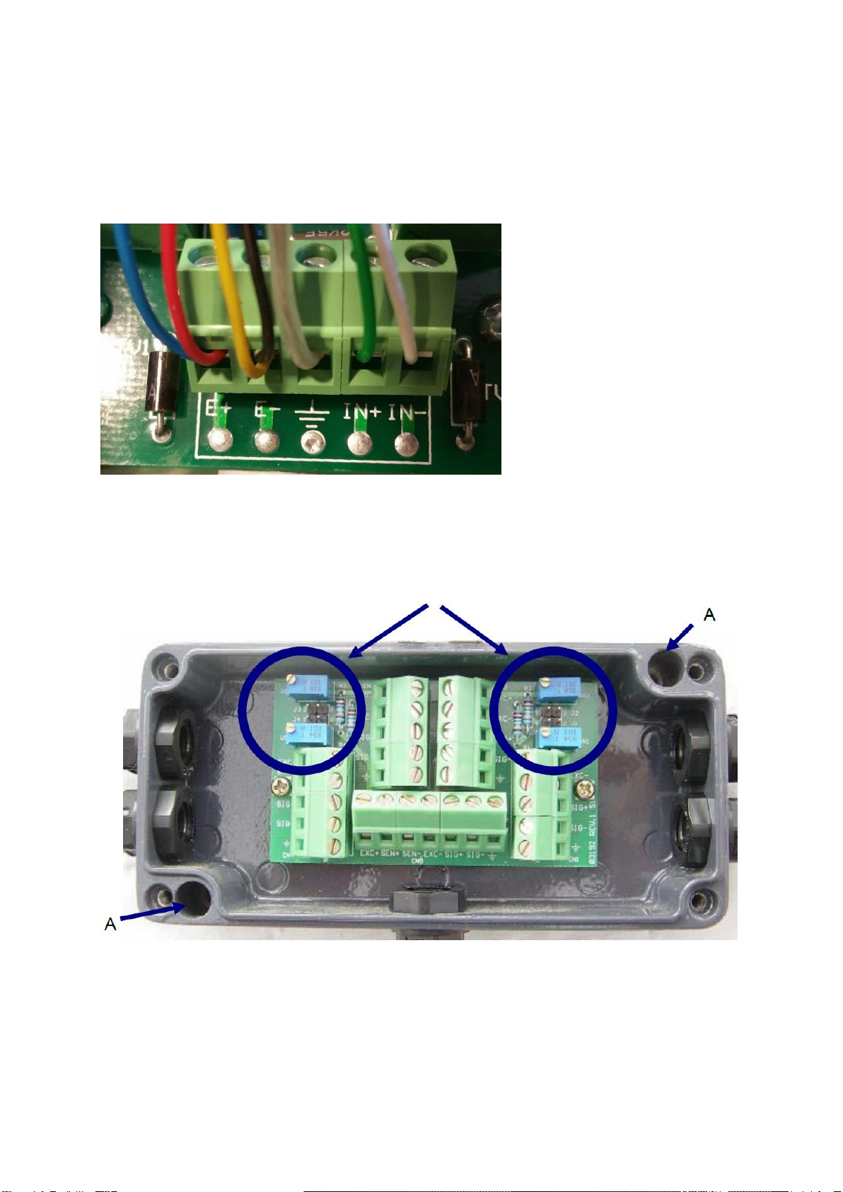
Before starting the calibration, make sure that all four jumpers are removed from J1,
J2, J3 and J4 and that all trimpots are set so that they do not affect the corner load.
This is achieved by turning the potentiometers VR1 (T1), VR2 (T2), VR3 (T3) and VR4
(T4) at least 20 turns clockwise or counterclockwise or until the end stop, which can
be signaled by a click sound.
If the trimpots VR1 (T1) and VR2 (T2) are turned clockwise and the potentiometers
VR3 (T3) and VR4 (T4) are turned counterclockwise, they reduce the load cell
performance. Place the corner load at all four corners one after the other and note the
highest measured value. Turn the corresponding trim pot to reduce the highest
measured value until it matches the lowest corner. (VR1 [T1] for load cell 1, VR2 [T2]
for load cell 2, VR3 [T3] for load cell 3 & VR4 [T4] for load cell 4)
Repeat the setting for the other corners as needed until all corners have the same
weight when the corner load is applied.
8 Small troubleshooting
8.1 The scale seems to indicate an incorrect weight
1. Unload the scale and check if the scale returns to zero.
2. Make sure that the object to be weighed is completely on the scale and is not
supported elsewhere.
8.2 The corners indicate unequal weights
1. Repeat the adjustment and the corner calibration (Chapter Fehler!
Verweisquelle konnte nicht gefunden werden.and 7.1)
2. Check the load cells for damage
8.3 The displayed value drifts quickly
1. Check that there is no water and dirt in the box.
2. Check the load cells and cables for damage.
3. Remove one load cell at a time from the box and, if necessary, carry out a cross-
exchange to locate a defective cell.
Use a load cell simulator to check if the evaluation unit works without errors and
displays stable values.
9 Declaration of conformity
To view the CE declaration, please click on the following link:
https://www.kern-sohn.com/shop/de/DOWNLOADS/
This manual suits for next models
1
Table of contents
Other sauter Industrial Equipment manuals
Popular Industrial Equipment manuals by other brands

Eclipse
Eclipse ecoflex Eco-100 PRO manual

fafnir
fafnir 350094 Technical documentation

HEIDELBERG
HEIDELBERG DryStar 2000 instruction manual

ZWAE
ZWAE NSW30 Installation and service manual

LCM SYSTEMS
LCM SYSTEMS CPA Operator instructions

DRIESCHER-WEGBERG
DRIESCHER-WEGBERG SF6 Operation – and Assembly Instruction

SPX Cooling Technologies
SPX Cooling Technologies Marley Geareducer 2200 user manual

Aerotech
Aerotech BA50 Series Hardware manual

Loctite
Loctite UVALOC 400 operating manual

Siemens
Siemens MOBILETT Plus HP Maintenance Instruction

Javo
Javo Rotofill user manual

Indexator
Indexator LINKSYS MPB1-80/45 KPL user manual