manuals.online logo
Brands
  1. Home
  2. •
  3. Brands
  4. •
  5. Savant
  6. •
  7. Extender
  8. •
  9. Savant HCX-1200 User manual

Savant HCX-1200 User manual

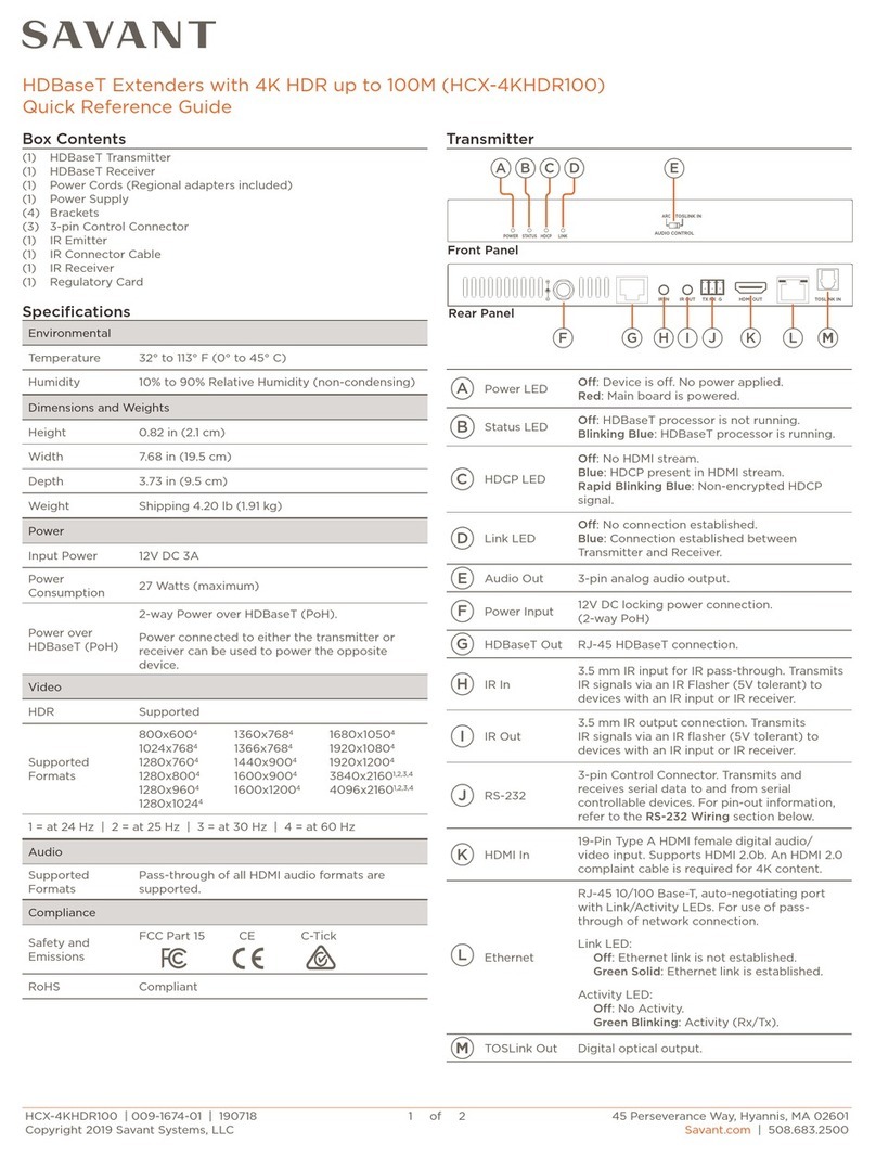
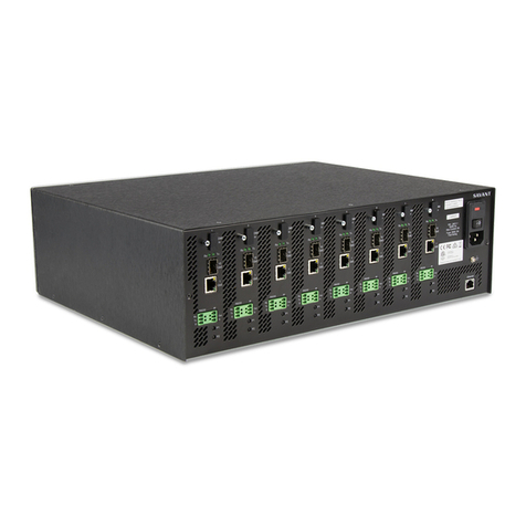
HDMI Over Fiber Extender HCX-1200 Quick Reference Guide 009-0308-04
Copyright ©2011 Savant Systems LLC. SAVANT®and RacePoint Blueprint™are trademarks of Savant Systems LLC.
Savant LLC reserves the right to change product specifications without notice.
770 Main Street, Osterville, MA 02655, Phone 508.683.2500, Fax 508.683.2600, http://www.savantav.com
The Savant HDMI Over Fiber Extender (HCX-1200) Quick Reference Guide provides the
steps necessary to install the HCX-1200.
Features
•Supports video resolutions up to 1080p, 1920 x 1200 and 2K
•3DTV Pass-Through
•Delivers highest quality signal of any HDMI extension method
•Extends HDMI and RS-232 up to 1000 feet (300m)
•Uses widely available single-strand multi-mode SC fiber optic cable
•Immune to electromagnetic interference (EMI)
•HDCP Compliant
•225 MHz (up to 12-bit YUV 444 @ 1080p)
•Dolby TrueHD and DTS Master Audio
Specifications -Transmitter and Receiver
Temperature
32°to 95°F (0°to 35°C)
Humidity
10% to 90% RH (non-condensing)
Height
1.2 in/3.0 cm
Width
4.2 in/10.7 cm
Depth
3.8 in/9.7 cm
Weight
0.45 lb/0.20 kg (weight of each unit)
5V DC Input Power
Power Consumption
120V AC, 50/60 Hz to 5V DC Power Supply
5 Watts (max) per unit
Video Amplifier Bandwidth
225 MHz
Input Video Signal
1.2 Volts p-p
Input DDC Signal
5 Volts p-p (TTL)
RS-232 Data Transmission Rate
115,200 kbps (max)
Max. Video Resolution Supported
1080p60, 1920 x 1200, 2K
Safety and Emissions
CSA NRTL/C and FCC Part 15 Class B
RoHS
Compliant
Unpack the Components
To unpack and mount the Transmitter and Receiver, refer to the diagram below for connection
information and do the following:
1. Open the box and remove the packing.
2. Remove the supplied items from the box (see Box Contents below).
Box Contents
•(1) Extender for HDMI over Fiber with Transmitter Unit
•(1) Extender for HDMI over Fiber with Receiver Unit
•(2) 5V DC Power Supply with locking power connector
•(1) Quick Reference Guide
Mount the Components
To mount the HCX-1200 transmitter and receiver, do the following: Place the components in
locations that provide adequate access to the connectors in order to route the power cables
and other required signal and control cables.
Transmitter -Front
1
P (Power LED)
•Red indicates the Transmitter is receiving 5V DC
power when 5V DC power supply is connected to
Transmitter and surge protected power source.
•Green indicates the Transmitter and Receiver are
communicating.
2
C (Calibration LED)
•Alternating Red and Green indicates the calibration is
in process.
•Green indicates calibration has been completed
3
IR Blaster
(35mm Mini-Stereo jack)
Not supported. Reserved for future use.
4
HDMI In
(Type A, 19-pin, locking)
Connect a High Definition source to this port.
5
RS-232
(DB-9 female)
Connect a Controlling Device to this port.
Transmitter - Rear
1
Fiber
(Fiber optic connector,
SC-Type)
Accepts one (1) strand of SC-terminated multi-mode fiber
optic cable that links the Transmitter and Receiver units
together. Only use multi-mode fiber optic cabling.
Important: The following maximum extension
distances can be achieved when using the following cables:
•100m (330 ft) on 62.5/125µm (OM1) multi-mode SC fiber
•300m (1000 ft) on 50/125µm (OM3) multi-mode SC fiber
2
5V DC
Locking power supply input. Provides 5V DC input power to
the Transmitter.
Receiver -Front
1
RS-232
(DB-9 male)
Connect a Controlling Device to this port.
2
HDMI Out
(Type A 19-Pin Female
Connect an HDTV display to this port.
3
IR (Window)
Not supported. Reserved for future use.
4
C (Calibration LED)
•Alternating Red and Green indicates the calibration
is in process.
•Green indicates calibration has been completed
5
P (Power LED)
•Red indicates the Receiver is receiving 5V DC power
when 5V DC power supply is connected to the
Receiver and surge protected power source.
•Green indicates the Receiver and Transmitter are
communicating.
Receiver -Rear
1
5V DC
Locking power supply input. Provides 5V DC input power to
the Receiver.
2
Ext - IR
Not supported. Reserved for future use.
3
Fiber
(Fiber optic connector,
SC-Type)
Accepts one (1) strand of SC-terminated multi-mode fiber
optic cable that links the Receiver and Transmitter units
together. Only use multi-mode fiber optic cabling.
Important: The following maximum extension
distances can be achieved when using the following cables:
•100m (330 ft) on 62.5/125µm (OM1) multi-mode SC fiber
•300m (1000 ft) on 50/125µm (OM3) multi-mode SC fiber
Transmitter and Receiver DIP Switches
Locate the DIP Switches on the Transmitter and Receiver units on the bottom of the units
under strips of tape. To change the DIP Switch settings use a small pointed object.
Note that DIP Switches are factory set to the OFF position.
Transmitter
DIP Switch
Function
1
EDID Mode: Local (OFF) or External (ON)
2
Deep Color Mode: 12-bit (OFF) or 8-bit (ON)
3
Calibration Mode: On (OFF) or Lock (ON)
4
Not Used
HDMI Over Fiber Extender HCX-1200 Quick Reference Guide 009-0308-04
Copyright ©2011 Savant Systems LLC. SAVANT®and RacePoint Blueprint™are trademarks of Savant Systems LLC.
Savant LLC reserves the right to change product specifications without notice.
770 Main Street, Osterville, MA 02655, Phone 508.683.2500, Fax 508.683.2600, http://www.savantav.com
Receiver
DIP Switch
Function
1
Not Used
2
Not Used
3
Calibration Mode: On (OFF) or Lock (ON)
4
Not Used
DIP Switch 1 -EDID Mode
OFF (Local EDID) (Not Recommended)
•When using this mode, copying all video and audio features of the connected device
assembles the EDID.
•Deep Color is supported in this mode and is manually controlled provided you set DIP
Switch 2 to the ON position. Deep Color is supported by the displays.
ON (Pass-Through EDID) (Default Mode)
•When using this mode, all video and audio features of the connected devices will be
passed to the source device. Deep Color is not supported.
DIP Switch 2 -Deep Color
OFF (Forces 8-bit Color) (Not Recommended)
•When using this mode, Deep Color is disabled in the EDID mode. Deep Color
management is only available when using Local EDID.
ON (Enables Deep Color - 12-bit Color) (Default Mode)
•When using this mode, Deep Color support is enabled. In the Pass-through EDID
mode (DIP Switch 1) this mode will have no effect on Deep Color since all EDID is
passed through.
DIP Switch 3 –Calibration (See Calibration Procedure)
OFF (Calibration Mode)
•When using this mode, Calibration functionality is enabled.
•DIP Switch 3 on both the Transmitter and Receiver must be set to the OFF position.
ON (Calibration Lock Mode)
•When using this mode, the Calibration settings are locked.
•DIP Switch 3 on both the Transmitter and Receiver must be set to the ON position.
Interconnect the Units
To interconnect the units, do the following:
1. Connect a High Definition source to the HDMI In port on the Transmitter unit using a
locking HDMI cable.
2. Connect a HD Display to the HDMI Out port on the Receiver unit using a user supplied
HDMI cable.
3. Connect an SC terminated fiber optic cable between the FIBER port on the Transmitter
unit and the FIBER port on the Receiver unit.
4. Optional: Connect a RS-232 cable from a RS-232 port on the Savant Controller (for
example) to the RS-232 port on the Transmitter unit. Connect another RS-232 cable
from the RS-232 port on the Receiver unit to a RS-232 port on the controlling device.
Important: Before connecting the 5V Power Supplies to the Transmitter and
Receiver units, do the Calibration Procedure.
Unit Interconnections (Example)
Calibration Procedure
These steps must be followed when setting up the Savant HDMI Over Fiber Extender for the
first time.
1. Disconnect power from the transmitter and receiver.
2. Connect the SC fiber optic cable between the Transmitter and Receiver units.
3. Set DIP Switch 3 on both the Transmitter and Receiver units to the OFF position.
4. Apply power from the source and to both the Transmitter and Receiver units.
The C (calibration) LED indicators on both the Transmitter and Receiver units will
alternate from red to green during the calibration process. The calibration process can
take up to 60 seconds to complete.
Note: No video will be displayed on the HD Display during this time.
5. After the calibration process has finished, the LED indicators on both the Transmitter
and Receiver units will be solid green.
6. Set DIP Switch 3 to the ON position on both the Transmitter and Receiver units to lock
the calibration settings.
Important If DIP Switch 3 is not set to the ON position, the calibration settings will not
be saved if there is power outage.
Note: If you change the fiber optic cable, repeat the calibration procedure.
By following the above procedure, the unit will not re-calibrate every single time a cable
(HDMI or Fiber) is hot plugged or the units are power cycled.
Calibration Troubleshooting
•If the Transmitter and Receiver units do not complete the calibration process, the C
LED indicators on both the Transmitter and Receiver units will be red.
oCheck the fiber connections carefully, cycle the power on both units and repeat
the calibration procedure.
•If the C LED indicator is green on one unit and red on the other unit, cycle the power
on the unit with the red indicator.
Note: Savant recommends that you cycle power on both units and repeat the
calibration procedure.
•If the calibration procedure continues to fail, contact Savant Technical Support.
Additional Documentation
Additional documentation for the HCX-1200 is available at: http://www.savantav.com > Dealer
Login > Knowledge Base > Products
•Refer to the RacePoint Blueprint™Programming Guide to configure the HCX-1200
into a Savant System.
•
Other Savant Extender manuals

Savant PAV-VIMVP1F2 Series User manual

Savant

Savant PAV-VIMVP1F2 Series User manual

Savant HCX-4KHDR40 User manual

Savant

Savant HCX-4KHDR40 User manual

Savant HCX-4KHDR40 User manual

Savant

Savant HCX-4KHDR40 User manual

Savant PAV-VIM1CP2 Series User manual

Savant

Savant PAV-VIM1CP2 Series User manual

Savant HCX-4KHDR100 User manual

Savant

Savant HCX-4KHDR100 User manual

Savant HCX-1010 User manual

Savant

Savant HCX-1010 User manual

Savant BLASTER User manual

Savant

Savant BLASTER User manual

Savant HCX-1100 User manual

Savant

Savant HCX-1100 User manual

Savant HCX-4KHDR100 User manual

Savant

Savant HCX-4KHDR100 User manual

Savant HCX-4KHDR100 User manual

Savant

Savant HCX-4KHDR100 User manual

Savant PAV-VIMAP8S Quick reference guide

Savant

Savant PAV-VIMAP8S Quick reference guide

Savant UCX-2000 User manual

Savant

Savant UCX-2000 User manual

Popular Extender manuals by other brands

Luxul Pro-WAV PWK2-24-1WFP7 Quick install guide

Luxul

Luxul Pro-WAV PWK2-24-1WFP7 Quick install guide

Mercusys MW300RE user manual

Mercusys

Mercusys MW300RE user manual

Epcom TITANIUM TT380PRO manual

Epcom

Epcom TITANIUM TT380PRO manual

Altimium TP503P-4K user manual

Altimium

Altimium TP503P-4K user manual

SC&T HE01SE user manual

SC&T

SC&T HE01SE user manual

LINK-MI LM-THF123HKM user manual

LINK-MI

LINK-MI LM-THF123HKM user manual

Uniden UM50 4G Quick install

Uniden

Uniden UM50 4G Quick install

SC&T VKM04 user manual

SC&T

SC&T VKM04 user manual

NETGEAR EAX11v2 user manual

NETGEAR

NETGEAR EAX11v2 user manual

Avenview HDMI-C5SP-8SRSR user guide

Avenview

Avenview HDMI-C5SP-8SRSR user guide

Abtus OPT-HDX11MT/A1 User's operation guide

Abtus

Abtus OPT-HDX11MT/A1 User's operation guide

TP-Link TL-WA830RE user guide

TP-Link

TP-Link TL-WA830RE user guide

EiRA ER2601EXP quick start guide

EiRA

EiRA ER2601EXP quick start guide

Black Box IC569A Quick installation guide

Black Box

Black Box IC569A Quick installation guide

Asus rp-n14 quick start guide

Asus

Asus rp-n14 quick start guide

Black Box ServSwitch ACU5010A user manual

Black Box

Black Box ServSwitch ACU5010A user manual

HighPoint Rocket EJ340 Quick installation guide

HighPoint

HighPoint Rocket EJ340 Quick installation guide

Ihse DXXi K472-SSH Quick setup

Ihse

Ihse DXXi K472-SSH Quick setup

manuals.online logo
manuals.online logoBrands
  • About & Mission
  • Contact us
  • Privacy Policy
  • Terms and Conditions

Copyright 2025 Manuals.Online. All Rights Reserved.