SawStop TSG-FDC User manual

OWNER’S MANUAL
FLOATING DUST COLLECTION GUARD
MODEL TSG-FDC

The saw shown on the front cover is the Industrial Cabinet Saw, Model ICS.
Your saw may look different.
Copyright SawStop, LLC
All Rights Reserved
Updates of this manual may be
available at www.sawstop.com
2nd printing, November 2017
SawStop, the SawStop blade logo, and the conguration of this product are either
registered trademarks or trademarks of SawStop, LLC. Software copyright by
SawStop, LLC. All rights reserved.

TO OUR CUSTOMERS
Thank you for purchasing the SawStop Floating Dust Collection Guard. We are condent you
will be pleased with its quality and performance.
This manual tells you more about your dust collection guard and how to operate and
maintain it. Please read the manual carefully. The manual also includes our warranty and
important safety information.
If you ever have any questions or comments, feel free to contact us at the address below.
SawStop, LLC
11555 SW Myslony Street | Tualatin, Oregon 97062 USA
Phone: (503) 570-3200
Fax: (503) 570-3303
Email: [email protected]
www.sawstop.com

HOW TO GET HELP
Missing Parts? Have Questions?
Our technical support team is standing by
M-F, 6:30am-5pm PST
to help with whatever you need.
503.582.9934
Give us a call at
SERVICE@SAWSTOP.COM
Email us at

TABLE OF CONTENTS
Product Specications.................................................................................
Parts Inventory..............................................................................................
Parts and Hardware Lists...................................................................................................
Tools Needed.....................................................................................................................
Assembly Instructions..................................................................................
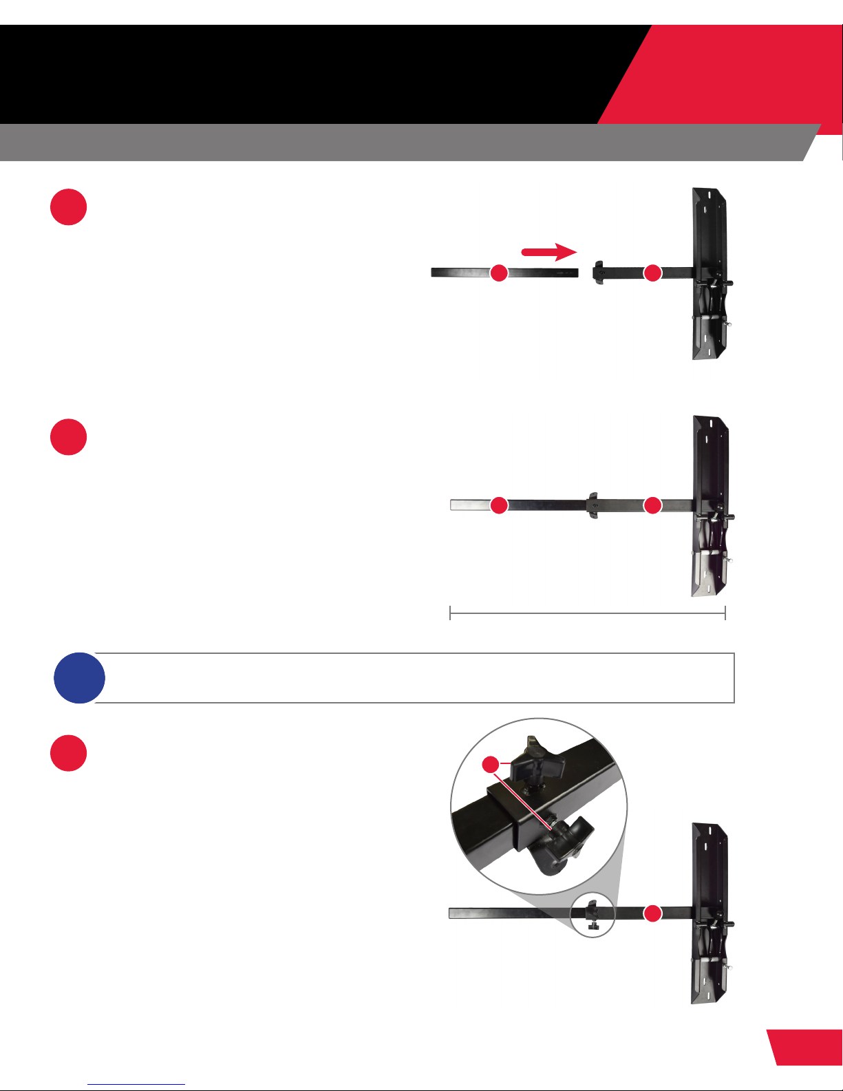
Attaching the Extension Leg to the Dust Collection Guard Mounting Bracket...................
Attaching the Dust Collection Guard Mounting Bracket to the Extension Table..............
Assembling the Leg Support Brackets..............................................................................
Attaching the Leg Support Brackets to the Dust Collection Guard Mounting Bracket....
Attaching the Leg Support Brackets to the Extension Table.............................................
Attaching the Dust Tubes to the Dust Collection Guard Mounting Bracket......................
Attaching the Floating Blade Guard to the Dust Tube....................................................
Attaching the Dust Hose to the Dust Tube and the Floating Blade Guard......................
Connecting to a Dust Collection System .........................................................................
Adjusting Your Floating Dust Collection Guard..........................................
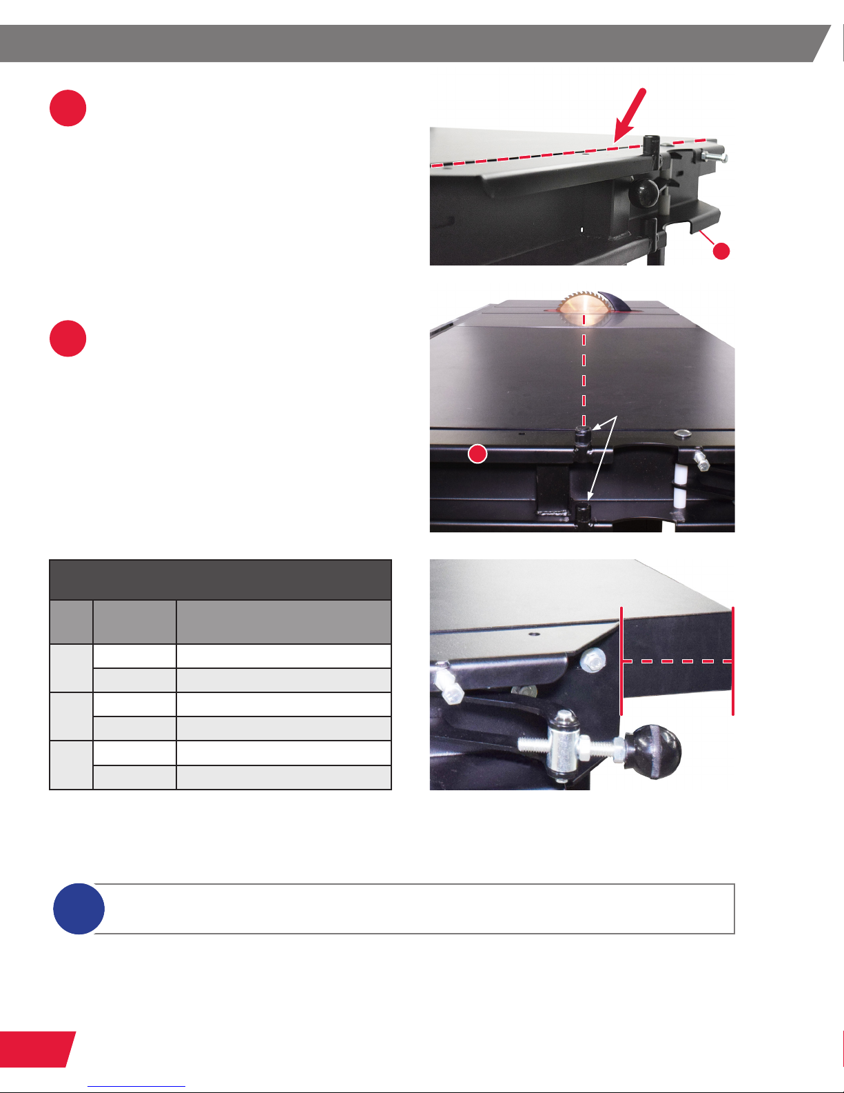
Adjusting the Parallelism of the Dust Tube Assembly........................................................
Adjusting the Length of the Dust Tube Assembly..............................................................
Adjusting the Floating Blade Guard Height.......................................................................
Adjusting the Floating Blade Guard Spring.......................................................................
Maintenance..................................................................................................
Reference......................................................................................................
Warranty............................................................................................................................
Safety.................................................................................................................................
Warnings...........................................................................................................................
Warning Labels..................................................................................................................
Exploded View...................................................................................................................
Parts List............................................................................................................................
1
2
2
3
4
4
5
9
10
11
14
16
18
19
20
20
20
21
22
23
24
24
25
26
26
27
28

1TSG-FDC OWNER’S MANUAL
PRODUCT SPECIFICATIONS
Product Specications
Net Weight 58 lbs
Floating Blade Guard Dimension 3.5” x 18.5”
Distance Between Blade and End of Extension Table 35.75” to 68”
Inner Dust Tube Diameter 3”
Outer Dust Tube Diameter 4”
Outer Dust Tube Height Above Table 13.6”
Outer Dust Tube Height Above Floor 33.5” to 50”
The SawStop Floating Dust Collection Guard is designed as a blade cover and dust
collection hood. It is intended for use on SawStop cast iron table saws. The transparent
oating guard back plate can be cut or removed to provide clearance for safety devices
such as riving knives, splitters, and anti-kickback pawls. The Floating Dust Collection
Guard is compatible with dado stacked blades.

2
TSG-FDC OWNER’S MANUAL
PARTS INVENTORY
Parts and Hardware Lists
PAGES:
2-3
Extension Leg (1)
Dust Collection Guard Mounting Bracket (1)
Leg Support Bracket (2)
Outer Dust Tube (1)
Inner Dust Tube (1)
Floating Blade Guard (1)
Dust Collection Hose (1)
Hardware Pack (1)
A.
B.
C.
D.
E.
F.
G.
H.
Parts
E D
G
C
F
H
B
A
The Floating Dust Collection Guard is shipped partially assembled. Please unpack the
parts carefully and conrm you have received each item on the list below.

3TSG-FDC OWNER’S MANUAL
•
•
•
•
Tools Needed
•
•
•
Drill with 1/4” and 7/64” Drill Bits
7/16”, 1/2”, and 9/16” Wrenches
10mm Wrench
4mm Allen Wrench
Measuring Tape
Flathead and Phillips Screwdrivers or
Driver Bits
Pen or Pencil
1/4”-20 Extension Leg Lock Knob (2)
M6 x 19 x 1 Washer (8)
M6 x 1.0 x 40mm Hex Head Bolt (4)
M6 x 1.0 Nut (4)
1/4”-20 x 3/4” Flat Head Socket Screw (2)
1/4”-20 x 4” Eye Bolt (2)
Leg Support Mounting Bracket (2)
1/4” Lock Washer (6)
1/4”-20 x 1/2” Hex Head Bolt (2)
M5 x 12 x 1 Washer (2)
M5 x 2.1 x 32 Button Head Phillips Screw (2)
M6 x 1.0 x 40 Button Head Socket Screw (1)
M6 x 1.0 Lock Nut (1)
1/4”-20 Nut (8)
Hose Clamp (2)
I.
J.
K.
L.
M.
N.
O.
P.
Q.
R.
S.
T.
U.
V.
W.
Hardware
I J
P Q R S T U
K L M
N
O V
W

4
TSG-FDC OWNER’S MANUAL
ASSEMBLY INSTRUCTIONS
Attaching the Extension Leg to the Dust Collection Guard Mounting Bracket
PAGES:
4-19
1
2
3
Slide the hollow end (the end
without the cap) of the extension
leg (A) about 3 inches into the leg
portion of the dust collection guard
mounting bracket (B).
Adjust the overlap between the
extension leg (A) and the dust
collection guard mounting bracket
(B) until the top of the dust
collection guard mounting bracket
approximately matches the height of
your extension table.
Thread the two 1/4”-20 extension
leg lock knobs (I) into the two
nuts on the dust collection guard
mounting bracket (B). Tighten the
extension leg lock knobs evenly to
secure the extension leg.
The extension leg lock knobs should
engage the extension leg and lock
it against further movement. This
will help prevent potential injury due
to unexpected movement of the
oating dust collection guard.
The exact height is not critical at this point, as it can be adjusted after the dust collection guard
mounting bracket is attached to the extension table.
i
HEIGHT OF YOUR EXTENSION TABLE
B
B
B
A
A
I

5TSG-FDC OWNER’S MANUAL
Attaching the Dust Collection Guard Mounting Bracket to the Extension Table
1
2
Place the at edge of the dust
collection guard mounting bracket
(B) against the right edge of the
extension table on your saw, with
the top of the dust collection guard
mounting bracket ush or just
below ush with the top of the
extension table.
Reference the table and gure
below for accurate placement of the
bracket based on your saw model
conguration. The mounting pins on
the dust collection guard mounting
bracket (B) should align with the
center of the blade.
The elongated mounting slots in the bracket will allow for some adjustment of the positioning if
needed once it has been mounted to the extension table.
i
B
B
The distance between the mounting bracket and the rear edge of the extension table
should match the value listed for your model saw in the table above.
Bracket Mounting
Saw Extension
Table
Distance Between Bracket
and Rear of Extension Table
ICS 36” 4”
52” 4”
PCS TGP2 36” 1 5/8”
TGP2 52” 1 5/8”
CNS TGP2 36” 1”
TGP2 52” 1”
MOUNTING
PINS

6
TSG-FDC OWNER’S MANUAL
3Place a mark on the extension table
in the center of each of the four
elongated mounting slots in the dust
collection guard mounting bracket
(B). Then place the dust collection
guard mounting bracket and
extension leg aside.
4Use a 1/4” drill bit to drill four
through-holes in the extension table
at the locations marked in step 3.
B
5Place the at edge of the dust
collection guard mounting bracket
(B) in the same position as in step 2,
with the mounting holes aligned with
your drilled through-holes.
B

7TSG-FDC OWNER’S MANUAL
8Check to make sure that the dust
collection guard mounting bracket
is still positioned correctly against
the extension. If the position needs
to be adjusted, make use of the
clearance provided by the
elongated slots.
6With the mounting holes aligned,
insert a single M6 x 1.0 x 40 hex
head bolt (K) through a
M6 x 19 x 1 washer (J), then through
one of the four exposed holes in
the dust collection guard mounting
bracket (B) and extension table, and
then through a second M6 x 19 x 1
washer (J) and a M6 x 1.0 nut (L).
Only nger-tighten the nut at this
time.
VIEW UNDER TABLE
7Repeat this process for the
remaining three holes in the dust
collection guard mounting bracket
and extension table.
B
J
J L
B
K

8
TSG-FDC OWNER’S MANUAL
9
10
Using a 10mm wrench on the head
of each bolt and an 10mm wrench
on each nut, tighten the nuts on the
bolts to secure the dust collection
guard mounting bracket to the
extension table.
Check to make sure that the
extension leg is vertical.
If necessary, adjust the extension
leg lock knobs and/or the bolts
attaching the dust collection guard
mounting bracket to the
extension table.

9TSG-FDC OWNER’S MANUAL
Assembling the Leg Support Brackets
1
2
3
4
Insert a 1/4”-20 x 3/4” at head
socket screw (M) through the eye
of an eye bolt (N), and then through
one of the holes in a leg support
mounting bracket (O). Then place a
1/4” lock washer (P) onto the screw,
followed by a 1/4”-20 nut (V). Only
nger-tighten the nut at this time.
Repeat this process for the other
eye bolt and leg support mounting
bracket.
Thread a 1/4”-20 nut (V) about half
way up the shaft of each eye bolt
(N).
Insert the shaft of an eye bolt (N)
through the hole in the bent end of a
leg support bracket (C), followed by
a 1/4” lock washer (P) and a 1/4”-20
nut (V). Only nger-tighten the nut at
this time.
M
N
V
N O P V
V
P
N
C

10
TSG-FDC OWNER’S MANUAL
Attaching the Leg Support Brackets to the
Dust Collection Guard Mounting Bracket
5Repeat this process for the other leg
support bracket.
Place the at, non-bent end of a
leg support bracket (C) against
the exterior side of the front tab
welded to the leg portion of the dust
collection guard mounting bracket
(B). Make sure the bent sections of
the leg support bracket (C) and the
leg support mounting bracket (O)
face out toward the front of the saw.
Insert a 1/4”-20 x 1/2” hex head
bolt (Q) through the hole in the
leg support bracket (C) and
then through the tab of the dust
collection guard mounting bracket,
followed by a 1/4” lock washer (P)
and a 1/4”-20 nut (V). Only nger-
tighten the nut at this time.
1
2
C
B
C
FRONT TAB
O
Q
C
V P

11 TSG-FDC OWNER’S MANUAL
3
1
Repeat steps 1-2 to attach the
other leg support bracket (C) to the
exterior side of the rear tab, making
sure the bent sections of the leg
support bracket and the leg support
mounting bracket face out toward
the rear of the saw. Only nger-
tighten the nut at this time.
Pivot the bent end (with the eye bolt
assembly) of the front leg support
bracket (C) up toward the underside
of the wooden extension table
support frame.
Attaching the Leg Support Brackets to the Extension Table
2Rotate the leg support mounting
bracket (O) and/or eye bolt (N)
until the at side of the leg support
mounting bracket is ush with the
outer portion of the extension table
support frame.
The point of contact between the leg support mounting bracket and the extension table can be
adjusted by loosening the nuts on the eye bolt, moving it in or out relative to the leg support
bracket, and then re-tightening the nuts.
i
REAR TAB
C
C
O
N
EXTENSION TABLE
SUPPORT FRAME

12
TSG-FDC OWNER’S MANUAL
3Make a mark on the underside of
the extension table support frame
in the center of the hole of the leg
support mounting bracket (O).
4
5
Pivot the leg support bracket back
down to rest on the oor. Drill a pilot
hole in the location you marked in
step 3 with a 7/64” drill bit.
Be sure to drill into the cross
support frame if you have a 36”
extension table.
Pivot the leg support bracket and
attached components up again
and align the leg support mounting
bracket hole with your drilled
pilot hole.
If you have a 36” extension table, rotate
the leg support mounting bracket (O) and/
or eye bolt (N) until the at side of the leg
support mounting bracket is ush with
the cross support frame of the
extension table.
i
EXTENSION TABLE
SUPPORT FRAME
EXTENSION TABLE
CROSS SUPPORT FRAME
EXTENSION TABLE
CROSS SUPPORT FRAME
O
O
N

13 TSG-FDC OWNER’S MANUAL
6Insert a M5 x 2.1 x 32 button head
phillips screw (S) through a
M5 x 12 x 1 washer (R) and then
through the exposed hole in the
leg support mounting bracket (O).
Secure the bracket to the underside
of the extension table support frame
using a Phillips screwdriver or drill.
7
8
Repeat steps 1-6 for the rear leg
support mounting bracket.
Check to make sure the extension
leg is still vertical and make any
necessary adjustments.
9Use a 7/16” wrench to tighten the
six 1/4”-20 nuts (V) on the eye bolts
for the front and rear leg support
mounting brackets.
O
S
R
V

14
TSG-FDC OWNER’S MANUAL
10 Use a 7/16” wrench to tighten the
two 1/4”-20 nuts (V) on both leg
support brackets.
Attaching the Dust Tubes to the Dust Collection Guard Mounting Bracket
1With the help of another person, lift
the dust tube assembly (comprised of
the inner and outer dust tubes (D,E))
and set them on the dust collection
guard mounting bracket. Be sure that
the pins on the dust collection guard
mounting bracket (B) (indicated by the
red arrows) pass through the holes
in the bracket on the outer dust tube
(indicated by the yellow circles).
IT IS RECOMMENDED THAT TWO PEOPLE ATTACH THE DUST TUBES,
AS THE DUST TUBE ASSEMBLY IS HEAVY AND COULD CAUSE SERIOUS
PERSONAL INJURY OR DAMAGE IF DROPPED.
2Pivot the dust tubes in towards
the dust collection guard mounting
bracket (B), so the dust tube
assembly rests securely against
the dust collection guard mounting
bracket (B).
V
B
B

15 TSG-FDC OWNER’S MANUAL
3Grasp the end of the 3/8”-16 dust
tube lock knob and pivot it towards
the dust tube assembly until the end
of the threaded portion of the lock
knob lines up with the depression
in the at plate portion of the outer
dust tube (D) and push it until it is
over center past the depression.
The amount of clamping force exerted
by the lock knob can be adjusted by
loosening the nut adjacent the pivot point
of the handle using a 9/16” wrench, and
threading the handle in or out. Once the
desired clamping pressure has been
reached, the nut can be re-tightened.
i
THE DUST TUBE LOCK KNOB WILL NOT SECURELY LOCK THE DUST
TUBE ASSEMBLY AGAINST THE DUST COLLECTION GUARD MOUNTING
BRACKET UNLESS IT IS JUST OVER CENTER PAST THE DEPRESSION.
DUST TUBE
LOCK KNOB
D
Other manuals for TSG-FDC
1
Table of contents
Other SawStop Dust Collector manuals
Popular Dust Collector manuals by other brands

Donaldson Torit
Donaldson Torit Downflo II DFT 2-4 Installation and operation manual

HOLZMANN MASCHINEN
HOLZMANN MASCHINEN ABS 2480 user manual

Nederman
Nederman FlexPAK 800 DX user manual

Record Power
Record Power CX2000 Original instruction manual

General
General 10-030CF M1 Setup & operation manual

JessEm
JessEm 05151 quick start guide