SBM SB-1100 User manual

Leading Image Processing Technology
We've been there when you needed
SB-1100
Currency Discrimination Counter
Service Manual
SBM Co., Ltd.
Ver. 1.04

CURRENCY DISCRIMINATION COUNTER SB-1100 SERVICE MANUAL
2
Important Safety Information
Always be careful when using the machine. To reduce the risk of fire electrical shock, and other injuries,
keep these safety considerations in mind when installing, using, and maintaining your machine:
Stability. Place the machine on a secure, stable surface. The machine can be seriously damaged if it
falls.
Power Supply. Provide correct power to the machine, as listed on the back of the machine. If you are
not sure of the type of power that is supplied to your office, call your electric company.
Grounding. If the plug has three prongs, it must be plugged into a grounded (three hole) outlet.
Grounded plugs and outlets are designed for your safety - do not try to make a three-prong plug fit into
a two-prong outlet by modifying the plug or outlet in any way. If you cannot insert the plug into your wall
outlet easily, then the outlet should be inspected by a qualified electrician.
Overload. Do not plug too many electrical devices into a wall outlet or an extension cord. An
overloaded outlet could be a reason of a fire and electrical shock hazard.
Cleaning. Before cleaning the machine, unplug it from the power outlet. Clean exposed parts with a
soft cloth slightly dampened with water. Do not use aerosol cleaners.
Gas Leaks. Never use any machine close to a gas leak. If you think gas is leaking, call the gas
company immediately. A small electrical spark in the machine could cause a fire or explosion.
Precaution
When using the machine, these precautions should always be followed.
1. Never push objects of any kind into your machine through the case or cabinet openings.
2. Do not use your machine near water, in wet locations, or outdoors.
3. Do not allow anything to rest on the power cord, line cord, or PC interface cable.
Do not locate your machine where the cords can be damaged by persons walking on them.
4. Do not allow pets to chew on the power cord or PC interface cable.
5. Use supplies or cleaning materials only as directed. Keep all supplies and materials out of the
way of children.
6. The power supply turns this machine on and off. Make sure that your machine is installed near
an outlet and is easily accessible.
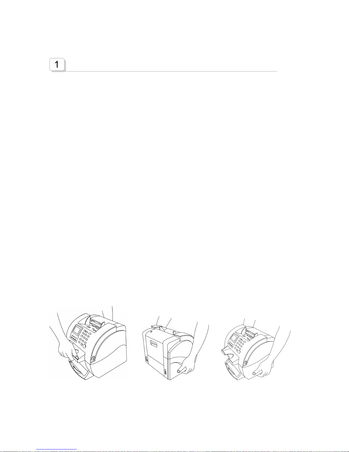
7. Never remove covers or guards that require a tool for removal. There are no operator
serviceable areas inside your machine. Refer servicing to authorized service personnel.
8. Never defeat interlock switches. This machine is designed to restrict operator access to unsafe
areas. Covers, guards and interlock switches are provided to ensure that the machine will not
operate with covers opened.

CURRENCY DISCRIMINATION COUNTER SB-1100 SERVICE MANUAL
3
9. Avoid direct viewing of the image sensor lights. The lamps are bright and, while not harmful,
they may cause an annoying afterimage. Always keep the rear cover closed during operation
and storage.
Safety Notes
Your machine and the supplies are designed and tested to meet strict safety requirements. Included are
safety agency examination and approval and compliance to established environmental standards.
Please read the following instructions carefully before operating your machine, and refer to them as
needed to ensure the continued safe operation of your machine.
FCC Warning
This device complies with part 15 of FCC rules. Operation is subject to the following conditions; this
device must accept any interference received, including interference that may cause undesired
operation.
Battery Warning
Risk of explosion, If battery is replaced by an incorrect type dispose of used batteries according to the
instructions.

CURRENCY DISCRIMINATION COUNTER SB-1100 SERVICE MANUAL
4
Table of Contents
Chapter 1 Installation 6
Unpacking List
Choosing a Location
Handling the Machine
Chapter 2 Description of the Parts 7
Outside
Inside (Left)
Inside (Right)
Inside (Rear-1)
Inside (Rear-2)
Inside (Rear-3)
Transfer Path & Sensors
Chapter 3 Function of each Board 11
Main Board
Image Board
Amp. Board
OPE Board
Conn. Board
Chapter 4 Interface between SB1000 and other units 13
Connect with PC
Connect with Serial Printer
Connect with Parallel Printer
Connect with Customer Display (Model: SV-110)
Chapter 5 Technical Functions Setup and Test 18
Control Mode Function
Test Mode Functions
Chapter 6 Adjustment 23
CIS
LCD Contrast
Hopper Sensor
Timing between ADF and Pickup Roller
Gap Adjustment: Brake
Gap Adjustment: Clutch
Gap of ADF
Timing Belt
Chapter 7 Shading 29
Motor Shading
CIS Shading
UV Shading

CURRENCY DISCRIMINATION COUNTER SB-1100 SERVICE MANUAL
5
MR, MR Array Shading
IR Shading.
Chapter 8 Upgrading Program 39
Main S/W Upgrading
Image S/W Upgrading
How to download image of banknote
The steps for getting LOG data
Chapter 9 Parts List 49
Chapter 10 Trouble shooting 58
LCD error messages
Fixing problems
Trouble shooting flow chart list
LCD is not lit
Do not start counting
Image M not working
Jam0 without actual jamming
Jam1 without actual jamming
Jam2/Jam3 without actual jamming
Can not check Reject Pocket Full
Can not Check Stacker Empty
Chapter 11 Maintenance 68
Daily Maintenance
Chapter 12 Assembly drawings 70
Top Level
Ass’y Cover Panel
Ass’y Upper and Lower Body
Ass’y Rear Plate
Ass’y Lower Body
Ass’y Lower Body Sub1
Ass’y Lower Body Sub2
Ass’y Lower Body Sub3
Ass’y Upper Body 1
Ass’y Upper Body 2
Ass’y Upper Body 3
Ass’y Lower Body Sub 1
Ass’y Lower Body Sub 2
Chapter 13 Connection Diagram 84
Chapter 14 Specification 85

CURRENCY DISCRIMINATION COUNTER SB-1100 SERVICE MANUAL
6
Installation
Unpacking List
1. SB-1100 1 Unit
2. AC Power Code 1 pc.
3. SB-1100 User's Guide 1 pc.
4. Cleaning Brush 1pc.
5. Glass Cleaning Cloth 1 pc.
6. Serial Cable (Connection between SB-1100 & PC) (option) 1 pc.
7. Printer Cable (used in connecting a printer) (option) 1 pc.
Choosing a Location
To help guarantee the trouble-free operation of your machine, place it on a flat, stable surface near your
workstation.
Do not place your machine:
In direct sunlight.
Near heat sources or air conditioners.
In dusty or dirty environments.
Handling the Machine
When handling or moving the machine, do not lift with grasping the Reject Pocket. The picture shows
how to lift the machine correctly.
(X) (X) (O)

CURRENCY DISCRIMINATION COUNTER SB-1100 SERVICE MANUAL
7
Description of the Parts
Outside
Front View
Rear View

CURRENCY DISCRIMINATION COUNTER SB-1100 SERVICE MANUAL
8
Inside (Left)
Inside (Right)
PBA Main
PBA Image
Encoder
Solenoid
Brake (Inside)
Main Motor
Clutch
Exit Motor
Idle

CURRENCY DISCRIMINATION COUNTER SB-1100 SERVICE MANUAL
9
Inside (Rear-1)
Inside (Rear-2)
UV, MR
MG Single
(Left, Right)
IR Trans.
SMPS
IR Receiver
(Infrared)
CIS
(Image Sensor)
UV(Tran.
Rcv.)
(Ultraviolet)

CURRENCY DISCRIMINATION COUNTER SB-1100 SERVICE MANUAL
10
Inside (Rear-3)
Transfer Path & Sensors
Jam2
Hopper
Rejecter
Stacker
IR Array & RP1
RP2/UV
MR Array & Single
JP
SP
Miss Feeding
Jam0
Jam1
Jam3
Sensor(Tx)
Sensor(Rx)
IR Trans.
UV Rcv.
MR Array
(Magnetic)
(Ultraviolet)
MG Single
(Magnetic)

CURRENCY DISCRIMINATION COUNTER SB-1100 SERVICE MANUAL
11
Function of each Board
Main Board
The part controlling on MAIN board is same as the following.
Control & Processing
Operation Panel : LCD Displaying, Key In
Sensors : Hopper, RP1, RP2, JP, SP, Reject, Stacker, Front Cover,
Encoder
Mechanism Control : Main Motor, Exit Motor, Brake, Clutch, Solenoid
Important parts on Main Board
Image Board
The part controlling on Image board is same as the following.
CPU
Blinking LED
Power LED
Current Driver
Main Motor Driver EEPROM
PLD
ADC
Solenoid Driver
SRAM

CURRENCY DISCRIMINATION COUNTER SB-1100 SERVICE MANUAL
12
Control & Processing
CIS : Image Processing
UV, MR Array, MR_L/R, IR : Counterfeit Detection
Printer : Serial Printer, Parallel Printer
Important parts on Image Board
Amp. Board
Input : MR Array(6 Channel), MG Single L/R
Function : Amplification
Output : to Image B’d
OPE Board
It operates all of the working process and display the operating condition.
Conn. Board
It connects ‘CLUTCH’, ‘JP/SP Rx Sensors’, ‘REJECT Rx/Tx Sensors’ with MAIN
B’d.
RS232C Driver
SRAM
CPU
Flash
PLD
Blinking LED
Image Processor
SDRAM
Power LED

CURRENCY DISCRIMINATION COUNTER SB-1100 SERVICE MANUAL
13
Interface between SB1000 and other units
Connect with PC
It should be connected with Com.1 port of PC.
Check the ‘Baud rate’
(Press ‘FUNC.’ ‘6. INTERFACE’ ‘2. BAUD RATE’ ‘4. 57600 BPS’ ‘ESC’)
FUNC. 6
2 4
ESC
1. SPEED
2. CONTRAST OF NOTE
3. START & MODE SET
4. BEEP
5. POCKET CAPACITY
6. INTERFACE
7. BANKNOTES CRITERIA
▼ 8. PARAMETERL
AUTO CF $
S : 0
T : 0
S $ 0
T $ 0
MIXED
7
. INTERFACE
1. PRINTER TYPE
2. BAUD RATE
3. DATA BIT
4. STOP BIT
5. PARATY
6. COLUMN LENGTH
2. BAUD RATE
1.9600 BPS
2.19200 BPS
3.38400 BPS
4. 57600 BPS
BAUD RATE 57600
Selected
AUTO CF $
S : 0
T : 0
S $ 0
T $ 0
MIXED

CURRENCY DISCRIMINATION COUNTER SB-1100 SERVICE MANUAL
14
Connect with Serial Printer
Check that the Printer type was set as ‘Serial Printer’
(Press : ‘FUNC.’ ‘6.INTERFACE’ ‘1.PRINTER TYPE’ ‘1.SERIAL PRINTER’ ‘ESC’)
FUNC. 6
1 1
ESC
Before connecting a printer to SB1100, please check the settings of the printer as below:
1. CR mode
Set to CR/LF
1. SPEED
2. CONTRAST OF NOTE
3. START & MODE SET
4. BEEP
5. POCKET CAPACITY
6. INTERFACE
7. BANKNOTES CRITERIA
▼ 8. PARAMETERL
AUTO CF $
S : 0
T : 0
S $ 0
T $ 0
MIXED
7. INTERFACE
1. PRINTER TYPE
2. BAUD RATE
3. DATA BIT
4. STOP BIT
5. PARATY
6. COLUMN LENGTH
1. PRINTER TYPE
1. SERIAL PRINTER
2. PARALLEL PRINTER
SERIAL PRINTER
Selected
AUTO CF $
S : 0
T : 0
S $ 0
T $ 0
MIXED

CURRENCY DISCRIMINATION COUNTER SB-1100 SERVICE MANUAL
15
2. Communication Mode
Xon/Xoff
SB1000 Printer Interface Setting
SB1100 supports only the below interface specification if the printer is set to Serial in Interface
Menu. Please refer to Set Function and Its Parameters (Ch. 7 Setup Interface and Print results’) in
User’s Guide.
1. BAUD : 9600
2. DATA : 8
3. STOP : 1
4. PARITY : NONE
5. PROTOCOL : XON/XOFF
The column size can be set to one of 30, 40, 60, and 80.
CITIZEN iDP3550/3551 Printer setting
1. Set the CR mode to CR+LF following the instruction of the User’s Manual of the printer. In case
of iDP3550 Model, #5 of DIP Switch 1 must be set to OFF or waste print paper.
2. Set the communication mode to Xon/Xoff by setting #4 of DIP Switch 2 to OFF.
3. Check whether the other parameters are set to the same value as SB1000’s.
4. Below figures show one example of the DIP Switch settings of iDP3550 (If you try to print “test
print”, you can check all settings)
DS1 (DIP Switch 1)
1 2 3 4 5 6 7 8 9 0
On
O O O O
Off
O O O O O O
DS2 (DIP Switch 2)
1 2 3 4 5 6 7 8
On
O O O O O
Off
O O O
5. Other parameters (recommended)
Baud Rate : 9600 bps
Data Bit : 8 bits
Parity : None
Handshake : XON/XOFF

CURRENCY DISCRIMINATION COUNTER SB-1100 SERVICE MANUAL
16
STAR SP200F Series Printer
Please check the settings are as like below:
Command mode : STAR
Control Code CR : Invalid
International Character Set: USA
Data Transmission Rate: 9600bps
Data Bit Length : 8 bits
Parity Check : None
Connect with Parallel Printer
Printer Protocol to print ‘Banknote serial number’ require SBM designed thermal printer and must be
purchased from SBM.
Check that the Printer type was set as ‘‘Parallel Printer’
(Press ‘FUNC.’ ‘6.INTERFACE’ ‘1.PRINTER TYPE’ ‘2.PARALLEL PRINTER’ ‘ESC’)
FUNC. 6
1. SPEED
2. CONTRAST OF NOTE
3. START & MODE SET
4. BEEP
5. POCKET CAPACITY
6. INTERFACE
7. BANKNOTES CRITERIA
▼ 8. PARAMETERL
AUTO CF $
S : 0
T : 0
S $ 0
T $ 0
MIXED

CURRENCY DISCRIMINATION COUNTER SB-1100 SERVICE MANUAL
17
1 2
ESC
Connect with Customer Display (Model : SV-110)
7. INTERFACE
1. PRINTER TYPE
2. BAUD RATE
3. DATA BIT
4. STOP BIT
5. PARATY
6. COLUMN LENGTH
1. PRINTER TYPE
1. SERIAL PRINTER
2. PARALLEL PRINTER
PARALLEL PRINTER
Selected
AUTO CF $
S : 0
T : 0
S $ 0
T $ 0
MIXED

CURRENCY DISCRIMINATION COUNTER SB-1100 SERVICE MANUAL
18
Technical Function to Setup and Test
To enter the Test Mode, press FUNCTION -> BATCH key then input the password “55757” and now
you enter into the Control Mode. You can move to any technical mode by pressing CF key (Test Mode)
or DENOM. key (Control Mode).
Press ‘UP/DOWN’ key or press directly a corresponding numeric key to select a function of the
technical mode. To exit from the current function, press FUNCTION key, and to exit completely from the
Technical Mode, press CLEAR key.

CURRENCY DISCRIMINATION COUNTER SB-1100 SERVICE MANUAL
19

CURRENCY DISCRIMINATION COUNTER SB-1100 SERVICE MANUAL
20
Control Mode Function
1. Error Stop Control
Sometimes there is need to prevent from stopping the machine even though some error is
occurred when you test the machine. If you want to do this, select “ERROR STOP OFF”. But
after the test, it must be restored to “ERROR STOP ON”
2. Sensor Level Control
In this mode, you can adjust the reference levels of the Hopper sensor, Double detection level,
and MR sensitivity level. To change the level, press UP/DOWN key and START key to save the
change then exit from the menu by pressing FUNCTION key.
3. System Report
Counting Report
In this mode, you can see the total number of the notes to be counted and the total error
occurrence. The hexadecimal code is used to express the number.
S/W version
You can check the version of Main and Image S/W.
S/N Display
You can check the serial no. of the unit with this function
S/N Setting
You can input the serial no. on the unit with this function
4. A/S Call No
While initializing process after the power is turned on, A/S call no. is displayed on LCD. In this
mode, you can set the telephone no of your local service provider. The number is available up
to 20 characters including ‘-‘ character. Input the number using numeric keys and then press
START/ENTER key to store it.
In input mode, MODE key is used as LEFT key, GT key as RIGHT, and DISPLAY key as “-“.
5. Shading
In order that a system may analyze a signal with a reference level, the system should know the
full swing of a waveform of a signal. Shading means that making a full swing reference
waveform to read the full level of a signal. If the machine rejects too many notes when it works
in Mixed mode or CF detection mode, then there is a possibility that the system cannot analyze
the input waveform. With this function, you can make a standard waveform for a system.
For more detailed information, please see chapter 8.
Other manuals for SB-1100
1
Table of contents
Other SBM Cash Counter manuals