3
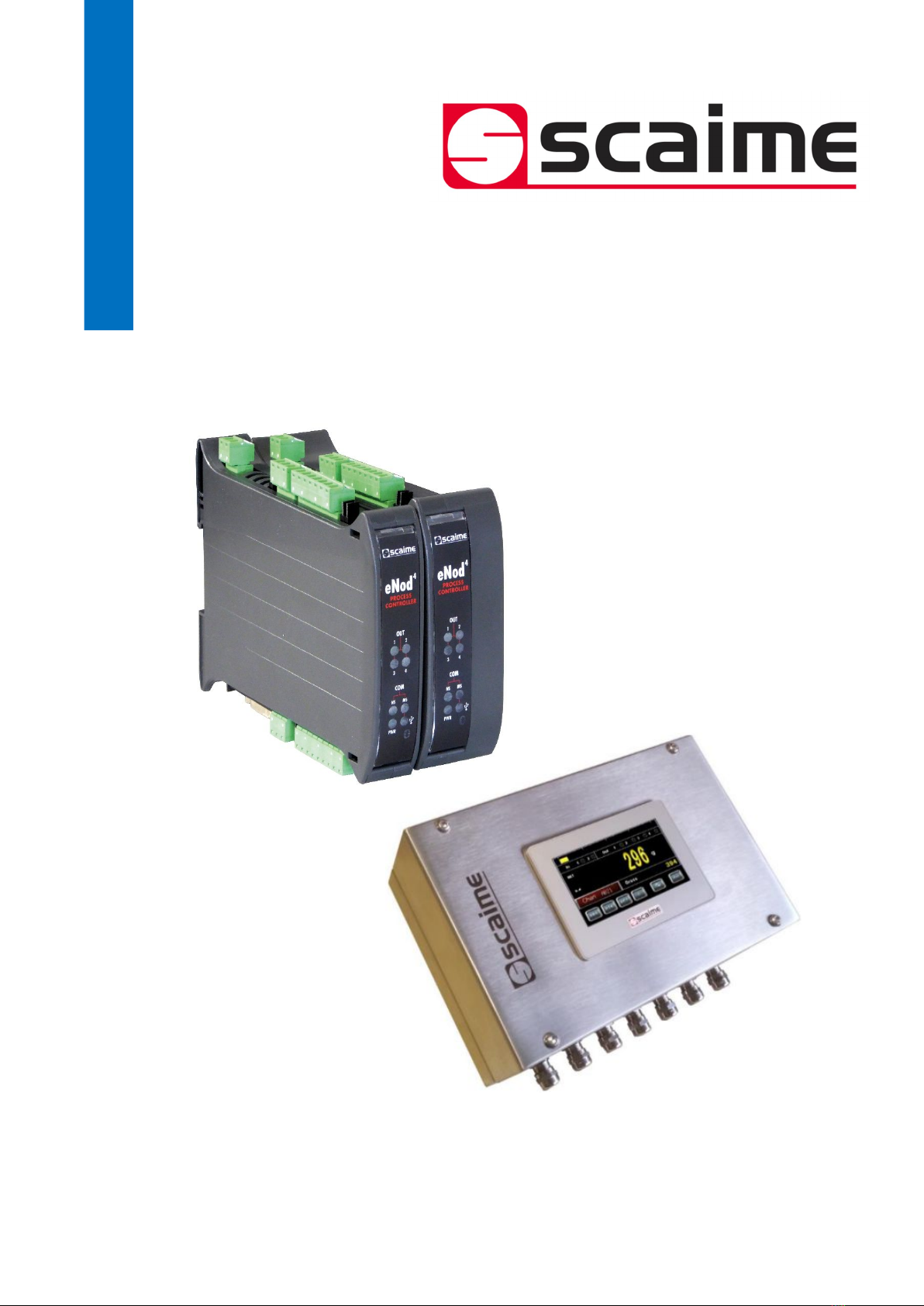
SCAIME Manual : NU-eNod4D-ETH-E-0418_216710-E.docx
7 FILTERS .................................................................................................................... 27
7.1 Filtering related to the A/D conversion rate .............................................. 27
7.2 Bessel low pass filter .................................................................................... 27
7.3 Notch filter ..................................................................................................... 27
7.4 Self-adaptive filter ........................................................................................ 27
8 MEASUREMENT AND STATUS ................................................................................. 28
8.1 Gross measurement ..................................................................................... 28
8.2 Net measurement ........................................................................................ 28
8.3 Tare value ..................................................................................................... 28
8.4 Factory calibrated points ............................................................................ 28
8.5 Logical IN/OUT level .................................................................................... 28
8.6 Preset Tare value .......................................................................................... 28
8.7 Measurement status ..................................................................................... 28
8.8 Weighing diagnosis ...................................................................................... 28
8.8.1 Global weighing diagnosis ................................................................... 28
8.8.2 Sensor input control ............................................................................... 28
9 INPUTS FUNCTIONING ........................................................................................... 29
9.1 Inputs assignment: ....................................................................................... 29
9.2 General functions: ........................................................................................ 29
9.3 Functions attached to an operating mode: .............................................. 29
10 OUTPUTS FUNCTIONING ...................................................................................... 30
10.1 Outputs assignment: .................................................................................. 30
10.2 General functions: ...................................................................................... 30
10.3 Functions attached to an operating mode: ............................................ 31
10.4 Feeding mode in dosing processes ......................................................... 31
10.5 Analog output (IO+ version) ..................................................................... 31
11 DOSING BY FILLING OPERATING MODE ............................................................ 33
11.1 Starting conditions ..................................................................................... 35
11.2 Cycle description ....................................................................................... 35
11.2.1 Flow rate control (optional) ................................................................ 35
11.2.2 Automatic taring at start ..................................................................... 35
11.2.3 Coarse feed effect neutralization time .............................................. 35
11.2.4 Fine feed level ...................................................................................... 35
11.2.5 Fine feed effect neutralization time ................................................... 36
11.2.6 Target weight and in-flight weight ..................................................... 36
11.2.7 Final stabilization time ......................................................................... 36
11.2.8 Tolerances ............................................................................................ 36
11.2.9 End of emptying level and emptying holding time .......................... 36
11.2.10 End of cycle waiting time ................................................................. 36
11.2.11 Effective end of cycle ....................................................................... 36
11.3 Inputs utilization .......................................................................................... 36
11.3.1 Start cycle ............................................................................................. 36
11.3.2 Suspend current cycle ........................................................................ 36
11.3.3 Stop cycle ............................................................................................. 37
12 DOSING BY UNLOADING OPERATING MODE .................................................... 38
12.1 Reloading management ........................................................................... 39
12.1.1 Reloading at the end of the cycle ..................................................... 40
12.1.2 Reloading at the start of the cycle ..................................................... 40
12.2 Cycle description ....................................................................................... 40
12.2.1 Flow rate control (optional) ................................................................ 40
12.2.2 Verification of the available product quantity .................................. 40