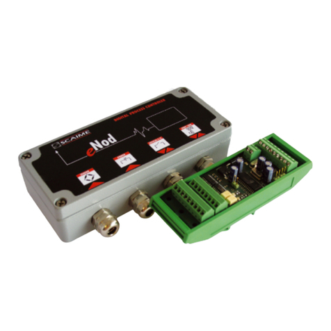
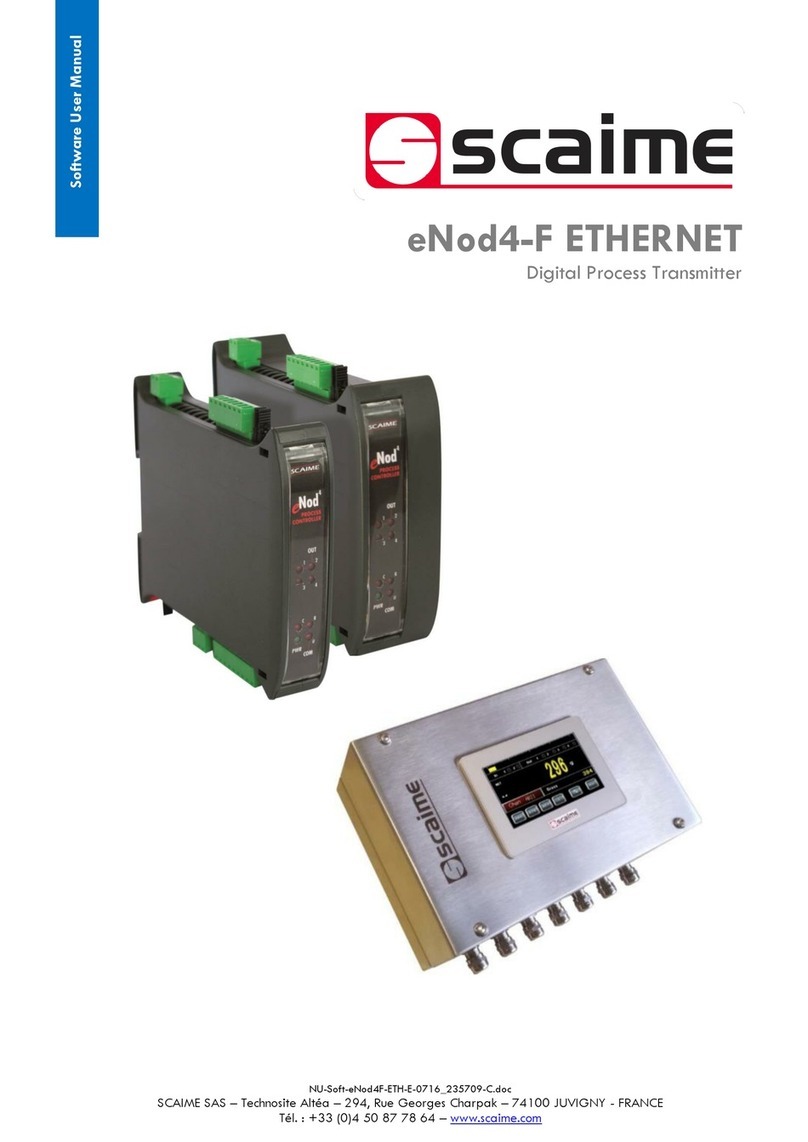
Scaime eNod4-B User manual

2/108
User manual SCAIME: NU-soft-eNod4B-ETH-E-0716_236709-C.doc
1 ENOD4 PRODUCT RANGE ...................................................................................... 6
1.1 General presentation..................................................................................... 6
1.2 Versions ........................................................................................................... 6
1.2.1 Communication protocol versions........................................................ 6
1.2.2 IO+ version............................................................................................... 6
1.3 eNodView Software........................................................................................ 7
2 COMMUNICATION AND FUNCTIONING MODES.................................................. 8
2.1 Communication protocols Modbus RTU and SCMBus ................................ 8
2.2 Functioning mode .......................................................................................... 8
2.3 HMI name ........................................................................................................ 8
2.4 Simultaneous functioning of communications ............................................ 9
2.4.1 Standard version ..................................................................................... 9
2.4.2 Profibus version...................................................................................... 10
2.4.3 Ethernet versions ................................................................................... 11
3 MODBUS RTU......................................................................................................... 12
3.1 Physical interfaces ....................................................................................... 12
3.2 Byte format.................................................................................................... 12
3.3 Modbus RTU supported functions................................................................ 12
3.4 Frames structure ........................................................................................... 12
3.4.1 Function (03H/04H) –read N input registers (N = 30 max)................ 12
3.4.2 Function (06H) –write single register................................................... 13
3.4.3 Function (10H) –preset multiple registers (N = 30 max).................... 13
3.4.4 Error frames ............................................................................................ 13
3.5 Address and Baud rate................................................................................ 13
3.6 Product identification................................................................................... 13
3.7 Measurement transmission.......................................................................... 14
3.8 EEPROM error management........................................................................ 14
4 SCMBUS / FAST SCMBUS ...................................................................................... 15
4.1 Physical interfaces ....................................................................................... 15
4.2 SCMBus and fast SCMBus features ............................................................. 15
4.3 Byte format.................................................................................................... 15
4.4 Frames structure ........................................................................................... 16
4.4.1 Transmission organization .................................................................... 16
4.4.2 Reading request .................................................................................... 16
4.4.3 Functional command request (tare, zero...) ...................................... 16
4.4.4 Error frame.............................................................................................. 16
4.5 Address and Baud rate................................................................................ 17
4.6 Product identification................................................................................... 17
4.7 Measurement transmission.......................................................................... 17
4.8 Continuous transmission .............................................................................. 17
4.9 EEPROM error management........................................................................ 17
5 MODBUS TCP ........................................................................................................ 18
5.1 Physical interface......................................................................................... 18
5.2 General information..................................................................................... 18
5.3 Frames structure ........................................................................................... 20
5.4 Network configuration ................................................................................. 20
5.5 Modbus TCP LED ........................................................................................... 21

3/108
User manual SCAIME: NU-soft-eNod4B-ETH-E-0716_236709-C.doc
5.6 I/O scanning ................................................................................................. 22
6 ETHERNET/IP .......................................................................................................... 24
6.1 Physical interface......................................................................................... 24
6.2 General information..................................................................................... 24
6.2.1 EtherNet/IP “Open standard” protocol ............................................... 24
6.2.2 Common Industrial Protocol (CIPTM) .................................................. 25
6.2.3 CIPTM Encapsulation Format................................................................ 26
6.3 Network configuration ................................................................................. 27
6.4 EtherNet/IP LED ............................................................................................. 28
6.5 I/O scanning / implicit messaging ............................................................. 28
6.5.1 Standard version (without IO+) ............................................................ 30
6.5.2 IO+ version............................................................................................. 30
7 PROFINET IO.......................................................................................................... 31
7.1 Physical interface......................................................................................... 31
7.2 Network settings ........................................................................................... 31
7.3 Definition of protocols roles......................................................................... 32
7.4 Main scenario ............................................................................................... 33
7.5 Alternative scenario: control, maintenance, supervision ........................ 34
7.6 Alternative scenario: eNod4 error application detected ........................ 34
7.7 PROFINET IO LEDs .......................................................................................... 34
7.8 Data arrangement........................................................................................ 35
7.8.1 Cyclic data (IO Data) ........................................................................... 35
7.8.2 Acyclic data (Records) ........................................................................ 35
7.9 PROFINET IO exchange of cyclic data....................................................... 35
8 ETHERCAT .............................................................................................................. 38
8.1 Physical interface......................................................................................... 38
8.2 Network settings ........................................................................................... 38
8.3 Communication protocol ............................................................................ 38
8.4 EtherCAT LEDs................................................................................................ 39
8.5 Data arrangement........................................................................................ 40
8.5.1 Acyclic data (Objects)......................................................................... 40
8.5.2 Cyclic data (IO Data) ........................................................................... 40
8.6 EtherCAT exchange of cyclic data ............................................................ 40
9 MEASUREMENT AND STATUS ................................................................................ 43
9.1 Measurement transmission.......................................................................... 43
9.1.1 Gross measurement.............................................................................. 43
9.1.2 Net measurement ................................................................................. 43
9.1.3 Tare value .............................................................................................. 44
9.1.4 Factory calibrated points ..................................................................... 44
9.1.5 Preset Tare value ................................................................................... 44
9.1.6 Measurement status.............................................................................. 44
9.2 Weighing diagnosis...................................................................................... 45
9.2.1 Global weighing diagnosis .................................................................. 45
9.2.2 Sensor input control .............................................................................. 46
10 PROCESSING FUNCTIONAL COMMANDS ......................................................... 47
10.1 Principles ..................................................................................................... 47
10.2 Functional commands list.......................................................................... 48
10.3 Functional commands description........................................................... 49

4/108
User manual SCAIME: NU-soft-eNod4B-ETH-E-0716_236709-C.doc
10.3.1 Reset ..................................................................................................... 49
10.3.2 EEPROM storage .................................................................................. 49
10.3.3 Restore default settings....................................................................... 49
10.3.4 Zero....................................................................................................... 49
10.3.5 Tare ....................................................................................................... 50
10.3.6 Cancel tare.......................................................................................... 50
10.3.7 Cancel last command........................................................................ 50
10.3.8 Theoretical scaling.............................................................................. 50
10.3.9 Zero adjustment .................................................................................. 50
10.3.10 Start physical calibration.................................................................. 50
10.3.11 Calibration zero acquisition ............................................................. 50
10.3.12 Segment 1 acquisition ...................................................................... 50
10.3.13 Segment 2/3 acquisition .................................................................. 50
10.3.14 Store calibration ................................................................................ 51
10.3.15 Logical outputs 1-4 activation/deactivation.................................. 51
10.3.16 Zero offset........................................................................................... 51
10.3.17 Dynamic zero .................................................................................... 51
10.3.18 Preset tare .......................................................................................... 51
10.3.19 Sensor input reference...................................................................... 51
10.3.20 Sensor input control .......................................................................... 51
10.3.21 Init speed sensor calibration............................................................ 51
10.3.22 End speed sensor calibration .......................................................... 52
10.3.23 Init belt length calibration ................................................................ 52
10.3.24 End belt length calibration............................................................... 52
10.3.25 Flow rate correction.......................................................................... 52
10.3.26 Start (batch/system) ......................................................................... 52
10.3.27 Stop (batch/system) ......................................................................... 52
10.3.28 Clear totalization & errors counter................................................... 52
10.3.29 Calibration of flow rate ..................................................................... 53
10.3.30 PID parameters auto-adjustment .................................................... 53
10.3.31 STOP & RESTART PID ........................................................................... 53
10.3.32 Clear great total ................................................................................ 53
10.3.33 Clear general total............................................................................ 53
11 CALIBRATION SETTINGS AND PROCEDURES ..................................................... 54
11.1 Principles ..................................................................................................... 54
11.2 Calibration methods .................................................................................. 55
11.3 Settings description .................................................................................... 55
11.3.1 Maximum capacity ............................................................................ 55
11.3.2 Number of calibration segments....................................................... 55
11.3.3 Calibration loads 1/2/3 ...................................................................... 55
11.3.4 Sensor sensitivity.................................................................................. 55
11.3.5 Scale interval....................................................................................... 55
11.3.6 Zero calibration ................................................................................... 56
11.3.7 Span coefficients 1/2/3 ...................................................................... 56
11.3.8 Span adjusting coefficient ................................................................. 56
11.3.9 Calibration place g value / place of use g value ........................... 56
11.3.10 Zero offset........................................................................................... 56
12 FILTERS ................................................................................................................. 57

5/108
User manual SCAIME: NU-soft-eNod4B-ETH-E-0716_236709-C.doc
12.1 Principles ..................................................................................................... 57
12.2 Settings list................................................................................................... 57
12.3 Settings description .................................................................................... 57
12.3.1 A/D conversion rate............................................................................ 57
12.3.2 Filters activation & order..................................................................... 58
12.3.3 Low-pass filter cut-off frequency ....................................................... 58
12.3.4 Limitations ............................................................................................ 59
12.3.5 Band-stop filter high cut-off frequency............................................. 59
12.3.6 Band-stop filter low cut-off frequency .............................................. 59
12.3.7 Moving average weight filter depth.................................................. 59
12.3.8 Moving average flow rate/speed filter depth.................................. 59
13 CONFIGURATION OF INPUT/OUTPUT ................................................................. 60
13.1 Principles ..................................................................................................... 61
13.1.1 Logical inputs....................................................................................... 61
13.1.2 Analog output (IO+ version) .............................................................. 63
13.1.3 Logical outputs .................................................................................... 65
13.2 Settings description .................................................................................... 67
13.2.1 Logical inputs assignment.................................................................. 67
13.2.2 Holding time (debounced time)........................................................ 68
13.2.3 Analog output(s) assignment (IO+ version) ..................................... 69
13.2.4 External value to control analog output (IO+ version).................... 69
13.2.5 Logical outputs 1&2 assignment........................................................ 70
13.2.6 Logical outputs 3&4 assignment........................................................ 71
13.2.7 Weight quantity per pulse on logical output.................................... 71
13.2.8 Set points functioning ......................................................................... 72
13.2.9 Set points high and low values .......................................................... 73
13.3 Input/output level....................................................................................... 74
14 LEGAL FOR TRADE OPTIONS............................................................................... 75
14.1 Principles ..................................................................................................... 75
14.2 Settings description .................................................................................... 75
14.2.1 Legal for trade switch ......................................................................... 75
14.2.2 Legal for trade software version ........................................................ 75
14.2.3 Legal for trade counter....................................................................... 76
14.2.4 Legal for trade checksum .................................................................. 76
14.2.5 Zero functions ...................................................................................... 76
14.2.6 Stability criterion.................................................................................. 76
14.2.7 Decimal point position........................................................................ 77
14.2.8 Weight unit ........................................................................................... 77
14.2.9 Flow rate time unit............................................................................... 78
14.2.10 Save Tare and Zero in non-volatile memory .................................. 78
15 BELT OPERATING MODES.................................................................................... 79
15.1 Settings description .................................................................................... 84
16 PROFINET IO........................................................................................................ 90
17 ETHERNET/IP REGISTER MAP ............................................................................... 95
18 ETHERNET/IP ODVA COMMONLY DEFINED REGISTER MAP............................ 100
19 MODBUS RTU AND MODBUS TCP REGISTERS TABLE ........................................ 102
20 CRC-16 CALCULATION ALGORITHM............................................................... 108

6/108
User manual SCAIME: NU-soft-eNod4B-ETH-E-0716_236709-C.doc
1ENOD4 PRODUCT RANGE
1.1 General presentation
eNod4 is a high speed digital process transmitter with programmable functions and powerful signal processing
capabilities. eNod4 offers operating modes for advanced process control both static and dynamic.
Quick and accurate:
•Analog to digital conversion rate up to 1920 meas/s with maximum scaled resolution of ±500 000 points.
•Digital filtering and measurement scaling.
•Measurement transmission up to 1 000 meas/s.
Easy to integrate into automated system:
•USB, RS485 and CAN communication interfaces supporting ModBus RTU, CANopen® and PROFIBUS-DPV1
(depending on version) communication protocols.
•Digital Inputs/Outputs for process control.
•Setting of node number by rotary switches and communication baud rate by dip switches.
•Integrated selectable network termination resistors.
•Wiring by plug-in terminal blocs.
1.2 Versions
1.2.1 Communication protocol versions
•Strain gauges load-cell conditioner with CANopen® and ModBus RTU communication.
•Strain gauges load-cell conditioner with Profibus DP-V1 and ModBus RTU communication.
•Strain gauges load-cell conditioner with Modbus TCP and ModBus RTU communication.
•Strain gauges load-cell conditioner with EtherNet/IP and ModBus RTU communication.
•Strain gauges load-cell conditioner with Profinet IO and ModBus RTU communication.
•Strain gauges load-cell conditioner with EtherCAT and ModBus RTU communication.
EDS, GSD, ESI and GSDML configuration files for above protocols can be downloaded from our web site:
http://www.scaime.com
1.2.2 IO+ version
In conjunction with all communication protocol versions, eNod4 can supports an opto-insulated board fitted with:
•2 additional digital inputs and 1 speed sensor dedicated input.
•0-5V or 0-10V analog output voltage.
•4-20mA, 0-24mA, 0-20mA or 4-20mA with alarm at 3.6mA analog output current.

7/108
User manual SCAIME: NU-soft-eNod4B-ETH-E-0716_236709-C.doc
1.3 eNodView Software
So as to configure eNod4, SCAIME provides eNodView software tool. eNodView is the software dedicated to eNod
devices and digital load cell configuration from a PC. This simple graphical interface allows accessing the whole
functionalities of eNod4 for a complete setting according to the application.
eNodView features and functions:
•eNod4 control from a PC
•Calibration system
•Modification/record of all parameters
•Measure acquisition with graphical display
•Numerical filters simulation
•Frequential analysis FFT
•Process control
•Network parameter
eNodView software is available in English and French version and can be downloaded from our web site:
http://www.scaime.com or ordered to our sales department on a CD-ROM support.

8/108
User manual SCAIME: NU-soft-eNod4B-ETH-E-0716_236709-C.doc
2COMMUNICATION AND FUNCTIONING MODES
2.1 Communication protocols Modbus RTU and SCMBus
Modbus RTU, SCMBus, and fast SCMBus communication protocols are accessible through AUX, USB. Modbus RTU or
Profibus only depending on version on DB9 connection.
The protocol can be changed via the « Functioning mode/ serial protocol » register (see below).
bits b9b8
Protocol
00
SCMBus
01
Modbus RTU
11
Fast SCMBus
Note: To be applied, any modification of this setting must be followed by an EEPROM back up and device reboots
(hardware or software).
2.2 Functioning mode
The « Functioning mode/ serial protocol » register offers the possibility to change the eNod4 application according to
the following list:
Note: To be applied, any modification of this setting must be followed by an EEPROM back up and device reboots
(hardware or software).
2.3 HMI name
The “HMI name” is a string of 4 characters freely usable to identify the node on any HMI connected to eNod.
Name
Modbus
address
EtherNet/IP
Class/
Attribute
(hex/dec)
Profinet
Record
Index
Profinet
cyclic Req
Code
EtherCAT
index/sub-
index
Type
Access
Functioning mode /
Serial protocol
0x003E
0x64/10
0x008C
R:0x02C2
W:0x02C3
0x2000 / 0x00
Uint
RW
HMI name
0x0034
0x64/21
0x00E0
/
0x3701 / 0x00
String
RW
bits
b1b0
Functioning mode
eNod4-T
eNod4-C
eNod4-D
eNod4-F
eNod4-B
00
Transmitter
Transmitter
Transmitter
Transmitter
Transmitter
01
/
Checkweigher
transmitter on request
Dosing by filling
Dosing
Belt scale
10
/
/
Dosing by unfilling
/
Belt weigh feeder

9/108
User manual SCAIME: NU-soft-eNod4B-ETH-E-0716_236709-C.doc
2.4 Simultaneous functioning of communications
2.4.1 Standard version
•DIN Version
PC Connection
AUX Connection
PLC Connection
eNodTouch
•BOX Version
Simultaneous
Communication
RS485 PLC
RS485 AUX
CAN
USB
Yes*
No
Yes*
RS485 PLC
Yes
No
RS485 AUX
Yes*
(*)Simultaneous use of CAN or RS485 PLC communication with USB or RS485 AUX can reduce performance of this
interface.
PC Connection
PLC Connection
PC Connection
AUX Connection
PLC Connection
PROFIBUS-DPV1
eNodTouch

10/108
User manual SCAIME: NU-soft-eNod4B-ETH-E-0716_236709-C.doc
2.4.2 Profibus version
•DIN Version
PC Connection
AUX Connection
PLC Connection
PROFIBUS-DPV1
eNodTouch
•BOX Version
Simultaneous
Communication
Profibus
RS485 AUX
USB
Yes*
No
Profibus
Yes*
(*)Simultaneous use of Profibus with USB or RS485AUX can reduce performance of this interface.
PC Connection
PLC
Connection
PROFIBUS
-
DPV1
PC Connection
AUX Connection
PLC Connection
PROFIBUS-DPV1
eNodTouch

11/108
User manual SCAIME: NU-soft-eNod4B-ETH-E-0716_236709-C.doc
2.4.3 Ethernet versions
•DIN Version
•BOX Version
Simultaneous
Communication
Ethernet
RS485 AUX
USB
Yes*
No
Ethernet
Yes*
(*)Simultaneous use of Ethernet with USB or RS485 AUX can reduce performance of this interface.
PC Connection

12/108
User manual SCAIME: NU-soft-eNod4B-ETH-E-0716_236709-C.doc
3MODBUS RTU
3.1 Physical interfaces
Modbus RTU communication protocol can be used either through eNod4 USB port, AUX port. Modbus RTU or Profibus
only depending on version on DB9 connection.
USB port behaves as a full duplex interface whereas the DB9 and AUX ports support half-duplex RS485
communication. Supported baud rates are 9600, 19200, 38400, 57600, and 115200.
For a complete description of the recommendations about eNod4 RS485 connection, please refer to the user manual
“characteristics and functioning” of the eNod4.
Note: using eNod4 through USB requires installing first the necessary USB drivers available on the website
http://www.scaime.com.
3.2 Byte format
Data transmitted to eNod4 thanks to Modbus RTU communication protocol must respect following format:
•1 start bit
•8 data bits
•no parity
•2 stop bits
Every Modbus RTU frame is ended by a CRC-16 2-bytes code whose polynomial generator is
(cf. CRC-16 calculation algorithm).
3.3 Modbus RTU supported functions
As a Modbus RTU slave, eNod4 supports following Modbus RTU functions:
Function
Code
read N registers*
03H/ 04H
write 1 register*
06H
write N registers*
10H
* 1 register = 2 bytes, maximum admitted value for N is 30.
Note: Broadcast addressing is not allowed by eNod4.
3.4 Frames structure
During a read or write transaction, the two bytes of a register are transmitted MSB first then LSB.
If a data is coded on 4 bytes (that means it requires two registers), the two LSB are stored in the low address
register and the two MSB are stored in the high address register.
3.4.1 Function (03H/04H) –read N input registers (N = 30 max)
•request command sent to the slave :
slave address
03Hor 04H
starting register
offset
N registers
CRC16
1 byte
1 byte
2 bytes
2 bytes
2 bytes
•slave response :
G(x) = x16+ x15 + x2+ 1

13/108
User manual SCAIME: NU-soft-eNod4B-ETH-E-0716_236709-C.doc
slave address
03Hor 04H
NB *
data 1
…
CRC16
1 byte
1 byte
1 byte
2 bytes
2 bytes
2 bytes
* NB: number of read bytes (= N*2)
3.4.2 Function (06H) –write single register
•request command sent to the slave :
slave address
06H
register offset
data
CRC16
1 byte
1 byte
2 bytes
2 bytes
2 bytes
•slave response :
slave address
06H
register offset
data
CRC16
1 byte
1 byte
2 bytes
2 bytes
2 bytes
3.4.3 Function (10H) –preset multiple registers (N = 30 max)
•request command sent to the slave :
slave address
10H
starting register
offset
N registers
NB
Data 1
…
CRC16
1 byte
1 byte
2 bytes
2 bytes
1 byte
2 bytes
2 bytes
2 bytes
•slave response :
slave address
10H
starting register
offset
N registers
CRC16
1 byte
1 byte
2 bytes
2 bytes
2 bytes
3.4.4 Error frames
•frame format in case of a transaction error :
slave address
Function code
+ 80H
error code
CRC16
1 byte
1 byte
1 byte
2 bytes
•Error codes meaning :
Error code
Meaning
description
01H
illegal function
Modbus-RTU function not supported by eNod4
02H
illegal data address
register address requested out of eNod4 register table
03H
illegal data value
forbidden data values for the requested register
04H
eNod4 not ready
eNod4 is not ready to answer (for example measurement
request during a taring operation)
3.5 Address and Baud rate
Address Modbus RTU
Meaning
Access
Type
0x0001
Address and Baud rate
RO
Uint
Reads the address and baud rate selected on the front panel via the rotary switches and dipswitches.
3.6 Product identification
Software and product versions of the eNod4 are accessible via Modbus RTU.

14/108
User manual SCAIME: NU-soft-eNod4B-ETH-E-0716_236709-C.doc
Address Modbus RTU
Meaning
Access
Type
0x0000
SW and product version
RO
Uint
The 12 LSB bits define the software version (073H= 115) and the 4 MSB bits define the product version (6Hfor the
eNod4).
3.7 Measurement transmission
As a master/slave protocol, measurement transmission in Modbus protocol is only done on master request.
3.8 EEPROM error management
Functioning and calibration parameters are stored in EEPROM. After every reset the entireness of parameters stored
in EEPROM is checked. If a default appears, measurements are set to 0xFFFF and default is pointed out in
measurement status.

15/108
User manual SCAIME: NU-soft-eNod4B-ETH-E-0716_236709-C.doc
4SCMBUS / FAST SCMBUS
4.1 Physical interfaces
SCMBus and fast SCMBus communication protocols can be used either through eNod4 USB port and AUX port.
USB port behaves as a full duplex interface whereas the DB9 and AUX ports support half-duplex RS485
communication. Supported baud rates are 9600, 19200, 38400, 57600, and 115200.
For a complete description of the recommendations about eNod4 RS485 connexion, please refer to the user manual
“characteristics and functioning” of the eNod4.
Note : using eNod4 through USB requires installing first the necessary USB drivers available on the website
http://www.scaime.com.
4.2 SCMBus and fast SCMBus features
SCMBus and its variant fast SCMBus can be imbricate into ModBus RTU protocol if the setting ‘communication
protocol’ is set to SCMBus or fast SCMBus. That means that eNod4 continues answering Modbus RTU frames but it
also allows the device to send frames coded according to SCMBus/fast SCMBus format.
Each protocol has its advantages:
•in SCMBus measurements are transmitted as ASCII with the decimal point and the unit integrated to the
frame
•fast SCMBus is dedicated to fast measurement transmission as the frames are the most compact as
possible
•both protocols allow to communicate without any master request (continuous transmission or sampling
triggered by a logical input)
4.3 Byte format
Data transmitted to eNod4 thanks to SCMBus or fast SCMBus communication protocol must respect following format:
•1 start bit
•8 data bits
•no parity
•2 stop bits
in SCMBus protocol, data is encoded as ASCII numeral characters (30H..... 39H) and ASCII hexadecimal characters (3AH
..... 3FH).
in fast SCMBus protocol, data is encoded as signed hexadecimal (see frame structure paragraph) below.
SCMBus CRC-8 byte is generated by the following polynomial:
G(x) = x8 + x7+ x4 + x3+ 1
The CRC-8 polynomial result can be determined by programming the algorithm corresponding to the following
diagram:

16/108
User manual SCAIME: NU-soft-eNod4B-ETH-E-0716_236709-C.doc
Note: The frame error detection can be ignored. Value 0xFF of the CRC-8 always is admitted by eNod4 and a received
frame which is ended by such CRC-8 is considered as a frame without any error.
•Fast SCMBus checksum byte is obtained by summing all the frame previous bytes then setting b7 bit to 1.
4.4 Frames structure
4.4.1 Transmission organization
•frame : eNod4 address first
•byte : lsb first
•multi-bytes data : MSB first
4.4.2 Reading request
•request
Address
Command
CR
CRC
1 Hex byte
1 Hex byte (command)
1 ASCII byte (0DH)
1 Hex byte
•SCMBus response
Address
Status
Value
CR
CRC
1 Hex byte
2 Hex bytes
N ASCII Hex bytes
1 ASCII byte (0DH)
1 Hex byte
If the ‘decimal point position’ and the ‘unit’ settings are assigned to a non-null value, the response frame when
transmitting measurement contains the decimal point character (2EH) and the unit that is separated from the
measurement value by a space ASCII character (20H).
•Fast SCMBus response
STX
Status word
Value
Cks
ETX
02H
2 Hex bytes
3 signed Hex bytes (2’s
complement)
Σ of previous bytes
and b7 bit set to 1
03H
Note: Because values are encoded in signed hexadecimal bytes format (2’s complement) some data bytes can be
equal to STX (02H) or ETX (03H) or DLE (10H) so before those specific bytes values a DLE (10H)byte is inserted. The
eNod4 address is not transmitted in the frame.
4.4.3 Functional command request (tare, zero...)
•request :
Address
Command
CR
CRC
1 Hex byte
1 Hex byte (command)
1 ASCII byte (0DH)
1 Hex byte
•response (SCMBus and fast SCMBus) :
Address
Command
CR
CRC
1 Hex byte
1 Hex byte (command)
1 ASCII byte (0DH)
1 Hex byte
If the command execution is successful, eNod4 sends back the request frame that has been received as an
acknowledgement.
4.4.4 Error frame
In case of an error upon reception of a request, eNod4 sends back an error frame that contains an error code:
•response (SCMBus and fast SCMBus) :
Address
Error code
CR
CRC
1 Hex byte
1 Hex byte (command)
1 ASCII byte (0DH)
1 Hex byte
•The error codes are listed below:

17/108
User manual SCAIME: NU-soft-eNod4B-ETH-E-0716_236709-C.doc
Error code
Meaning
Description
FEH
unknown command
requested command is not supported by eNod4
FFH
error during command execution
ex. : tare when gross meas.<0
4.5 Address and Baud rate
Address and baud rate identical to Modbus RTU (See § Modbus RTU)
4.6 Product identification
Product identification identical to Modbus RTU (See § Modbus RTU)
4.7 Measurement transmission
Measurement transmission can be triggered by a master request but it might also be triggered and used through the
following options:
•transmission triggered by a rising or falling edge on a logical input
•transmission at a configurable period (defined in ms) while a logical input is maintained at a given logical
level
•continuous transmission at a configurable period (defined in ms) after a master request. The transmission
is then stopped by another master instruction, be careful not to use this mode in half-duplex at a too high
rate.
4.8 Continuous transmission
SCMBus and fast SCMBus communication protocols allow eNod4 to transmit measurements at a user-defined rate
without the need for successive master queries. To perform this measurement acquisition mode, it is necessary to set
first the ‘sampling period’ (in ms):
Address SCMBus
Description
Accès
Type
0x003F
SCMBus Measurement
transmission period
RW
Uint
A value of 0 implies that measurement transmission is synchronized on the A/N conversion rate. The continuous
transmission is triggered and stopped by reception of the following commands:
SCMBus/fast SCMBus functional command
Command code
start net measurement transmission
E0H
start factory calibrated points transmission
E1H
start brut measurement transmission
E2H
stop continuous transmission
E3H
Note 1: the measurement transmission rate also depends on the baud rate. So, to achieve the fastest transmission, it
is necessary to use the highest baud rate.
Note 2: as RS485 is a half-duplex communication medium, it can be a little hard to transmit the ‘stop continuous
transmission’ query if the bandwidth is saturated. Therefore, prefer USB communication channel to reach the highest
measurement transmission rate.
4.9 EEPROM error management
EEPROM management identical to Modbus RTU (See § Modbus RTU)

18/108
User manual SCAIME: NU-soft-eNod4B-ETH-E-0716_236709-C.doc
5MODBUS TCP
5.1 Physical interface
eNod4 is fitted with an Ethernet interface on RJ45 connectors and is galvanically isolated.
The Auto-Crossover function is supported. Due to this fact the signals RX and TX may be switched on ETH1 and ETH2
interfaces.
Because Modbus TCP (or Modbus TCP/IP) shares the same physical and data link layers of traditional IEEE 802.3
Ethernet, physical interface remains fully compatible with the already installed Ethernet infrastructure of cables,
connectors, network interface cards, hubs, and switches.
eNod4 allows topologies in tree, line or star network. It also allows ring-shaped topology since RSTP (Rapid Spanning
Tree Protocol) has been implemented (eNod4 is a simple node and cannot act as network supervisor).
Every eNod4 drives two Ethernet ports and has an internal switch and hub functions, respectively the different circuits
which are related to the special features of some Real-Time-Ethernet systems to build up a line structure.
5.2 General information
eNod4 is fitted with an Ethernet communication interface that supports protocols TCP (Transmission Control Protocol)
and IP (Internet Protocol). These protocols are used together and are the main transport protocol for the internet.
When Modbus information is sent using these protocols, the data is encapsulated by TCP where additional
information is attached and given to IP. IP then places the data in a packet (or datagram) and transmits it on Ethernet
network.
Construction of a Modbus TCP data packet and simplified OSI model communication layers representation:
TCP must establish a connection before transferring data, since it is a connection-based protocol.
When a configuration change occurs (change of Ethernet parameters, set
default params via eNodView or eNodTouch) eNod4 Modbus-TCP
absolutely must not be reset or power cycled within 10 seconds after send
of the change. This could permanently damage the eNod. MS LED blinks
green or red cyclically when in this "damaged" state.
!

19/108
User manual SCAIME: NU-soft-eNod4B-ETH-E-0716_236709-C.doc
The Master (or Client in Modbus TCP) establishes a connection with the Slave (or Server) eNod4. The Server eNod4
waits for an incoming connection for the Client. Once a connection is established, the Server eNod4 then responds to
the queries from the Client until the Client closes the connection.
Modbus TCP/IP uses well-known specific port 502 to listen and receive Modbus messages over Ethernet.
Note: eNod4 does not support Modbus RTU over TCP protocol (simply put, this is a Modbus RTU message transmitted
with a TCP/IP wrapper and sent over a network instead of serial lines).
eNod4 supports Modbus TCP (or Modbus TCP/IP) protocol: a document Modbus Messaging on TCP/IP
implementation guide provided by Schneider Automation outlines a modified protocol specifically for use over
TCP/IP. The official Modbus specification can be found at Modbus organization (www.modbus.org).
ADU (Application Data Unit) and PDU (Protocol Data Unit): aside from the main differences between serial and
network connections stated above, there are few differences in the message content between Modbus TCP and
Modbus RTU.
Starting with Modbus RTU frame (ADU), the checksum disappears. From now on data integrity is granted by Ethernet
Data Link layer. Slave ID address is suppressed and supplanted by an identifier (Unit ID) that is a part of a
complementary data header called MBAP (Modbus Application Protocol) header. The MBAP header is 7 bytes long.
MBAP header: fields are defined below:
fields
Length
(bytes)
Description
Client (Master)
Server (Slave)
Transaction
Identifier
2
Transaction pairing
(request / response Modbus)
Initiated by the Client
Echoed back by the
Server
Protocol
Identifier
2
0 = MODBUS Protocol
Initiated by the Client
Echoed back by the
Server
Length
2
byte count of the remaining fields
(Unit ID + Function Code + Data)
Initiated by the Client
(request)
Initiated by the Server
(response)
Unit Identifier
1
Idendification of a remote server
(non TCP/IP or other buses), 0x00
or 0xFF otherwise
Initiated by the Client
Echoed back by the
Server
Supported functions: identical to Modbus RTU ones.
•Read multiple registers* : 03H/ 04H
•Write single register* 06H
•Write multiple registers* 10H

20/108
User manual SCAIME: NU-soft-eNod4B-ETH-E-0716_236709-C.doc
*1 register = 2 bytes
Maximal number of registers = 123
5.3 Frames structure
•By default and as in Modbus RTU, during a read or write transaction, the two bytes of a register are
swapped. The MSB is transmitted first and then the LSB. However it may be possible using eNodView
software to invert the swapping of data in a register.
•if a data is coded on 4 bytes (that means it requires two registers) , the two LSB are stored in the low
address register and the two MSB are stored in the high address register Modbus RTU request command
example sent to the slave in hexadecimal:
Slave address
03Hor 04H
First register address
N registers
CRC16
1 byte
1 byte
2 bytes
2 bytes
2 bytes
11
03
00 7D
00 03
97 43
•Equivalent request in Modbus TCP:
Transaction
Identifier
Protocol
Identifier
Message
length
Unit Identifier
03Hor 04H
First register
address
N registers
2 bytes
2 bytes
2 bytes
1 byte
1 byte
2 bytes
2 bytes
00 01
00 00
00 06
FF
03
00 7D
00 03
Modbus exception codes: like in Modbus RTU a server eNod4 may generate an exception response to a client
request.
•Exception codes table:
Error code
Exception
Description
01
Illegal Function
The function code received by eNod4 in the query is not allowed or
invalid.
02
Illegal Data Address
The data address received in the query is not an allowable address for
eNod4 or is invalid.
03
Illegal Data Value
A value contained in the query data field is not an allowable value or
out of the limits
06
eNod4 Device Busy
eNod4 is not ready to answer (for example measurement request
during a taring operation).
5.4 Network configuration
Every eNod4 is identified on the network by an IP address, a subnet mask and a default gateway address. Network
configuration can only be set using eNodView software at minimum version V.
IP address: the IP address is comprised of two parts: the network address or Net ID (first part), and the host address
or Host ID (last part). This last part refers to a specific machine on the given sub-network identified by the first part.
The numbers of bytes of the total four that belong to the network address depend on the Class definition (Class A, B,
or C) and this refers to the size of the network.
Class C subnets share the first 3 octets of an IP address, giving 254 possible IP addresses for eNod4 device. Recall that
the first 00Hand last FFHIP addresses are always used as a network number and broadcast address respectively.
eNod4 default local IP* address is 192.168.0.100
*if IP static configuration set
Subnet mask: a Subnet Mask is used to subdivide the host portion of the IP address into two or more subnets. The
subnet mask will flag the bits of the IP address that belong to the network address, and the remaining bits correspond
to the host portion of the address.
Other manuals for eNod4-B
3
Table of contents
Other Scaime Transmitter manuals