Scanjet BIO 25 User manual

#Bio25 11
Instruction Manual
BIO 25
Scanjet Marine AB
SALES OFFICE
Södra Långebergsgatan 36
P.O. Box 9316
SE-400 97 Göteborg, Sweden
Telephone +46 313 387 530
Telefax +46 313 387 540
E-mail office@scanjet.se
Web www.scanjet.se
FACTORY
Törnedalsgatan 1
P.O. Box 2
SE-275 21 Sjöbo
Telephone +46 416 513 100
Telefax +46 416 511 656
E-mail factory@scanjet.se
VAT SE556291242701

#Bio25 11 – 140813Page 2 of 40
This Manual Applies for the Following Products:
Type Date
SCANJET BIO 25 2014-08-13
Spare Parts Department
Contact Information
Read “9. How to Order Spare Parts” on page 25
Scanjet Marine AB
Törnedalsgatan 1
P.O. Box 2
SE-275 21 Sjöbo, Sweden
Telephone +46416 513 100
Telefax +46416 511 656
E-mail spares@scanjet.se
This manual is intended to assist in the handling and operation of the
Scanjet BIO 25 Tank Cleaning System. Continuous product improvement
is the policy of Scanjet Marine AB and we reserve the right to alter the
specifications at any time without prior notice.

#Bio25 11 – 140813 Page 3 of 40
Contents
1. Introduction.................................................................................................. 4
2. Safety Instructions ........................................................................................ 5
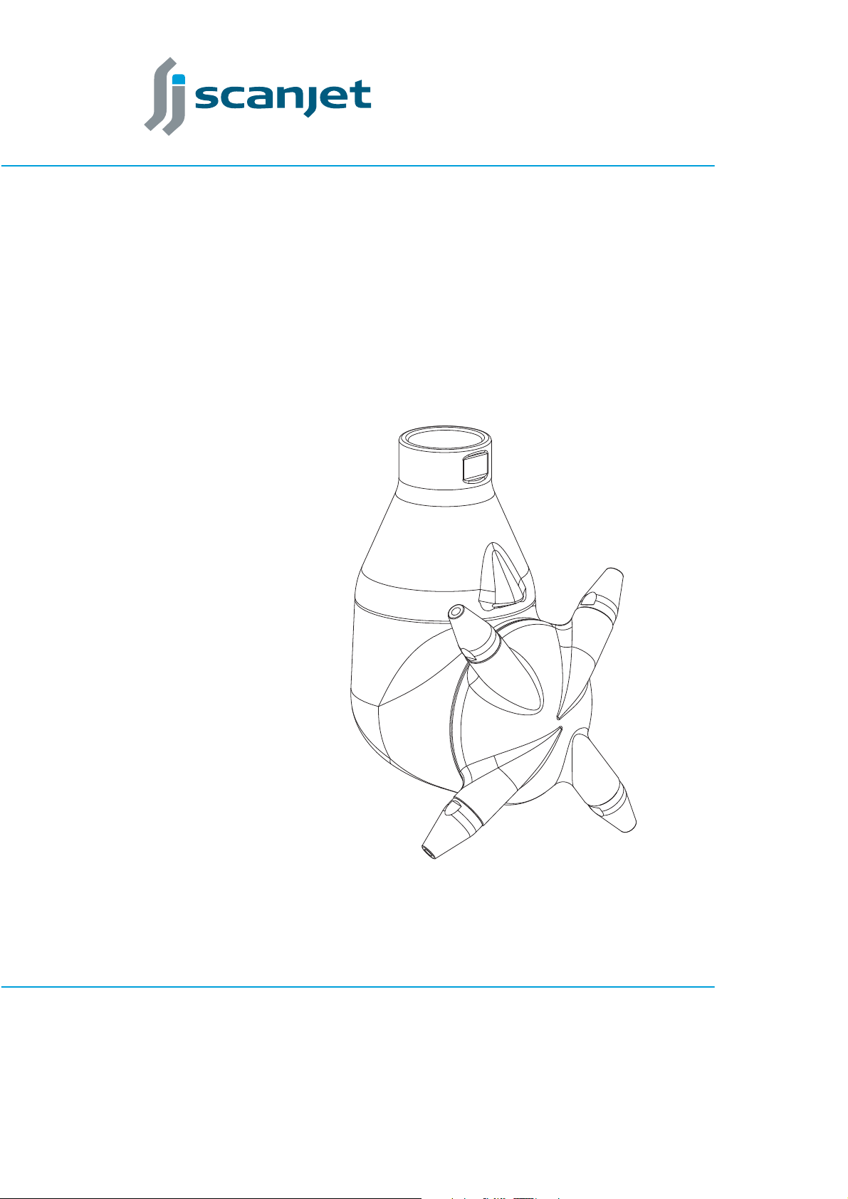
3. General Description...................................................................................... 6
4. Technical Data .............................................................................................. 7
4.1. Specifications..................................................................................................7
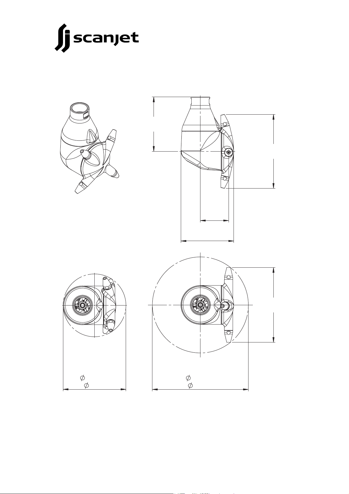
4.2. Dimensions BIO 25 .........................................................................................8
5. Performance Data......................................................................................... 9
6. Installation Instructions............................................................................... 12
6.1. Connecting to Supply Line ............................................................................13
7. Maintenance............................................................................................... 14
7.1. Preventive maintenance ................................................................................14
7.2. Service kits....................................................................................................15
7.3. Service intervals ............................................................................................16
7.4. Disassembly ..................................................................................................17
7.5. Reassembly ...................................................................................................21
8. Trouble Shooting Guide.............................................................................. 24
9. How to Order Spare Parts........................................................................... 25
10. Exploded Drawing View ........................................................................... 26
11. Spare Parts List - BIO 25......................................................................................27
12. Spare Parts List - Old Versions ............................................................................29
13. Accessories ............................................................................................... 30
13.1. Welding Adapter.........................................................................................30
14. Service Kit Contents ................................................................................. 32
15. Basic Settings............................................................................................ 33
15.1. BIO 25 - 4 nozzles .......................................................................................33
16. Tool Kit ..................................................................................................... 34
16.1. Standard Tool..............................................................................................34
16.2. Optional Tool..............................................................................................34
17. Service Card.............................................................................................. 35
18. Claim Report ............................................................................................ 37

#Bio25 11 – 140813Page 4 of 40
1. Introduction
The Scanjet BIO 25 is a highly versatile machine for use in hygienic applications as
well as other industrial applications. Its unique design makes it easy to install, use
and maintain as well as reduces the pressure drop through the machine.
The BIO 25 is per standard delivered with two or four nozzles in different nozzle
sizes, between Ø5mm and Ø18mm.
A special nozzle configuration with two extra nozzles cleaning the outside of the
machine provides unmatched self cleaning capability.
This manual has been prepared as a guide for persons who will be operating and
maintaining the tank cleaning machine. The key for long machine life will always
be carefully planned maintenance. If this is properly executed the Scanjet BIO 25
till keep servicing you for years.

#Bio25 11 – 140813 Page 5 of 40
2. Safety Instructions
• If the machine is used in potentially explosive atmospheres then tapes or
joint sealing compounds, which are electrical insulators, must not be used
on threads or joints, unless an electrical connection is otherwise established
to ensure an effective grounding. In addition, connection pipe work must be
electrically conductive and grounded to the tank structure. The resistance
between the nozzle and the tank structure should not exceed 20 000
Ohm. This is important in order to avoid any build up of static electricity
in the machine. For further information see CENELEC R044-001 Safety of
Machinery, guidance and recommendations for the avoidance of hazards
due to static electricity.
• When the equipment is operating in potentially explosive atmospheres,
measures have to be taken to verify that the tank is inert at all times during
cleaning operation. This is to avoid sparks and possible explosions since fluids
moving at high velocities through air causes electrostatic build up in the
media. As an extra precaution the cleaning media could be made conductive.
• The machine should be installed in accordance with national regulations for
safety and other relevant regulations and standards.
• Precautions should be made to prevent starting of the tank cleaning
operation, while personnel are inside the tank or otherwise can be hit by
jets by the jets.
• In EU-countries the complete system have to comply with EU-machine
directive and should be CE-marked. In North America consult Underwriters
Laboratory for any specific regulatory needs relative to the entire CIP (Clean
In Place) System.
• Ear protection should always be used when operating machine.
• Be careful not to drop the tank cleaning machine/equipment when lifting
and/or carrying. Dropping the machine could cause serious injuries. Never
stand underneath the machine during mounting or operation.
• The equipment may only be used for tank cleaning operations as described
in this manual.
• The equipment has not been assessed as a safety related device as referred
to in directive 94/9EC Annex II, clause 1.5
Always follow these instructions before taking the BIO 25 into service!

#Bio25 11 – 140813Page 6 of 40
3. General Description
The Scanjet Bio 25 is a media driven and lubricated tank cleaning machine. No
lubrication substances such as oil, grease etc. are used. All materials in contact
with the machine meet the general standards for hygienic process. Ceramic
and tungsten bearings are standard for an extra long service life. The unique
design of the Scanjet BIO 25 makes it completely self-cleaning and self-cleaning.
There are no interior pockets where water and dirt can accumulate, making this
machine one of the best choices for hygenic applications.
Functional Principle
When cleaning media enters the machine it first passes through a turbine and a
worm gearbox, then a nozzle housing leading it out through the nozzles and into
the tank. The turbines rotation drives the worm gearbox, making the machine
rotate around its own axle and at the same time, the nozzle housing is forced to
rotate clockwise.
A combined motion of the machines body and nozzle housing creates a criss-
cross cleaning pattern inside the tank. After 6 1/8 rotation of the nozzle housing,
a first course pattern has been created. This process is repeated 8 times, each
time indexed from each other until a full cleaning pattern has been created.
When this is finalized, after 47 rotations of the machine body, or 49 rotations of
the nozzle housing, the first cycle will be repeated.
Cleaning of tanks is a process depending on a number of factors; soilage, distance
between nozzles and tank walls, cleaning media, temperature etc. All of these
factors need to be considered before a proper cleaning can be accomplished.
The rotation speed of the machine idepends on flow rate through the machine.
Higher flow rate makes the turbine spin faster and because of this the machine is
equipped with different turbines according to nozzle size and intended operating
parameters.

#Bio25 11 – 140813 Page 7 of 40
4. Technical Data
4.1. Specifications
Weight : 7,0 kg (15,4 US Pounds)
Operating pressure range : 3-14 bar (40-200 psi)
Nominal pressure range : 5-12 bar (70-175 psi)
Max pressure : 14 bar (200psi)
Max working temperature : 95ºC (200ºF)
Max ambient temperature : 140ºC (284ºF)
Materials : AISI 316L, PTFE/GLASS (alt. PE1000),
PEEK, Tungsten, Al2O3

#Bio25 11 – 140813Page 8 of 40
4.2. Dimensions BIO 25
Max. Rotation
285 mm
( 11,2 in)
(7,3in)
Min. Opening
185 mm
(8,6 in)
(6,3 in)
(3,3 in)
83 mm
160 mm
217 mm
155 mm
(6,1 in)
220 mm
(8,7 in)

#Bio25 11 – 140813 Page 9 of 40
5. Performance Data
Under performance data Scanjet presents Effective Jet Length.
Effective Jet Length is defined as the distance between the nozzle and the tank
surface where the jet achieves 250 mm water column (50lbs/sqr.ft) impact force
at tank surface. The Effective Jet Length is measured at horizontal and static
conditions.
The Jet Length is affected by a lot of different factors such as rotation speed of
the machine (velocity of the jet at the tank surface), temperature of the cleaning
media, cleaning agent used and so on.
The vertical jet length can be estimated to be approximately 1/3 less than the
horizontal jet length.
The following graphs show the flow, effective jet length (radius) and complete
cleaning time for each combination of inlet pressure and nozzle diameter. Other
nozzle diameters and maximum jet lengths are available upon request.
Please note that when equipped with non-return check valve, the flow will
decrease an estimated 10%.
Flow vs Pressure
The inlet pressure has been measured at the machine inlet. In order to achieve
the same performance as indicated in these curves the pressure drop in the
supply line must be taken into consideration.
45678910
5
15
25
35
45
4XØ7 mm
4XØ8 mm
4XØ9 mm
psi
bar
m³/h
4XØ6 mm
60 80 100 120 140
50
100
150
200 4XØ10 mm
USgpm

#Bio25 11 – 140813Page 10 of 40
Effective Jet Length
The jet length is measured as effective jet length. Maximum jet length is
available upon request.
Please contact Scanjet for assistance with proper selection.
45678910
5
6
7
8
9
10
11
12
13
14
15
4XØ7 mm
4XØ8 mm
4XØ9 mm
psi
bar
m
4XØ6 mm
60 80 100 120 140
20
25
30
35
40
45
50
4XØ10 mm
ft

#Bio25 11 – 140813 Page 11 of 40
Complete Pattern Time at Different Inlet Pressure
45678910
5
10
15
20
25
4XØ7 mm
4XØ8 mm
4XØ9 mm
psi
bar
Min.
4XØ6 mm
60 80 100 120 140
4XØ10 mm

#Bio25 11 – 140813Page 12 of 40
6. Installation Instructions
General Installation Instructions: The Scanjet BIO 25 cleaning machine is
designed to be installed in a vertical upright or inverted position, however, the
machien may operate horizontally or in any other desired position.
Filtration: It is recommended to install a 100 micron filter in the supply line in
order to avoid large particles lodging inside the machine. All supply lines should
be flushed to remove dirt and particles before connecting the machine to the
system.
Cleaning Media: Only media compatible with the materials listed on the
reference list of parts for your model should be used. See “4. Technical Data”
on page 7.
After Use Cleaning: Depending on the type of cleaning that has been
performed and the type of cleaning media used, a procedure for after use
flushing of the cleaning system should be developed for your application. In
general, a fresh water flush is recommended after each cleaning process.
Pressure: Hydraulic shocks may damage the system. In order to avoid shocks
increase pressure gradually from 0 to maximum operating pressure over 5-7
seconds. Do not exceed 14 Bar (200 PSI) inlet pressure! Higher pressure in
combination with higher flow rates will increase consumption of wear parts and
could result in major leakage.
Warning! If the machine is used in potentially explosive
atmospheres then tapes or joint sealing compounds, which are
electrical insulators, must not be used on threads or joints, unless an
electrical connection is otherwise established to ensure an effective
grounding. In addition, connection pipe work must be electrically
conductive and grounded to the tank structure. This is important in
order to avoid any build up of static electricity in the machine.
NOTE! The machine is only self-draining if installed in a vertical
position, upright or inverted.

#Bio25 11 – 140813 Page 13 of 40
6.1. Connecting to Supply Line
Never attach the Scanjet BIO 25 by grabbing the nozzle housing! Always use
proper tools, and turn on the threaded connection as shown in the picture below.
When threading the inlet connection of the tank cleaning machine to the
cleaning media connection, Scanjet recommends that Food Grade Teflon tape
or any other appropriate food grade anti-seizing compound is used to avoid
metal galling. (Galling means that threads clamp together and cannot easily be
loosened.)
Following anti-seize compounds is recommended for use with food
industry, “FDA approved”
Loctite Product Numbers: Scanjet Article No.
8014: Food Grade Anti-Seize; 32 oz. can 250061-0,9

#Bio25 11 – 140813Page 14 of 40
7. Maintenance
7.1. Preventive maintenance
In order to keep your Scanjet tank cleaning machine servicing you as an efficient
tool in your tank cleaning operations, it is essential to care for maintenance.
Following a simple preventive maintenance program will keep your tank cleaning
machine in good condition and the machine will maintain its high performance.
The following recommended, preventive maintenance program is based on tank
cleaning machines working in average conditions. However, a cleaning machine,
which has a rough and dirty job to do, will need more frequent attention than
one working in ideal conditions. It is recommended that the maintenance
program is adjusted to suit such a situation.
Only use proper tools when servicing the machine; see chapter “16. Tool Kit” for
Scanjet standard tool kit. Never use excessive force or hammer components
together or apart. Always follow all assembly/disassembly steps in the order
described in this manual. Never assemble components without previous cleaning;
this is especially important at all mating surfaces. Work only in a clear well lighted
working area.
Good maintenance is careful and regular attention!
NOTE! Timely replacement of bearings will prevent costly damages to
the gears. However, all bearing bushes, made from high performance
PEEK (PolyEtherEtherKetone) material, are mounted with a press-fit
and should not be removed unless they need to be replaced.
Using any other than Scanjet original parts will invalidate
the warranty.

#Bio25 11 – 140813 Page 15 of 40
7.2. Service kits
Tank cleaning machines are mostly installed and operated in extremely rough
conditions. In order to ensure continued safe operation of the Scanjet tank
cleaning machines it is advised to follow given service instructions.
Scanjet has identified components which should been checked at regular
intervals and replaced if necessary, because of wear or damage. This is important
in order to avoid unplanned stops or breakdowns and to assure safe, smooth
and trouble free operation of the tank cleaning machines. The components that
may be subject to wear and need replacement have been included in service kits,
naturally optimized for each specific model and type of Scanjet tank cleaning
machine.
Service intervals are described on the following page. Note that the intervals
may be more frequesnt for machines installed in any other position than vertical,
upright or inverted.
Service kits are rapidly available and easy to order, as well as being more
economical compared to ordering of parts individually.
The service kits are specified on page 32 and forward.
Scanjet part no. Description
KIT BIO25-500 Wear kit for 500 hours of service
KIT BIO25-1000 Wear kit for 1000 hours of service
T BIO 25 Scanjet basic tool kit including all necessary
tools to service the machine

#Bio25 11 – 140813Page 16 of 40
7.3. Service intervals
Every 500 Working Hours
1. Order the service kit for 500 hours service “KIT BIO25-500”
2. Thoroughly flush the machine prior to disassembly and insure that no
particles remain in the machine.
3. Disassemble machine as described on the following pages.
4. Upon complete disassembly of the machine, all parts should be thoroughly
washed and/or degreased in the appropriate manner, then inspected
accordingly.
5. Inspect seals and bushings and gears for wear; locate position numbers from
“Exploded Drawing View” on page 26. Replace if unduly worn.
6. Reassemble the machine. A service card is included with this manual; see
page 35. This should be completed each time service is performed on the tank
cleaning machine so that a proper maintenance record/history is kept.
Every 1000 Working Hours
1. Order the special service kit for 1000 hours service “KIT BIO25-1000”
2. Do the same inspection as for 500 hours
3. Replace the parts in the service kit. Check all parts for wear, replace if
necessary.

#Bio25 11 – 140813 Page 17 of 40
7.4. Disassembly
1. Use Scanjet tool 25257 to remove
the round spring holding the
locking shafts in place, inside the
connection.
2. Remove the four locking shafts. This
can be done by rotating the entire
machine or by using a tool to force
them out.
3. When the locking shafts are out,
the inlet cone can easily be removed
by lifting it straight upwards.
4. Be sure to hold the
machine steady, use soft
material when holding it
to avoid damaging the
surface. Use Scanjet
tool 25255 to undo
the support bearing,
then insert the locking
shafts again. This is
done in order to line up
the stator and prevent
damages while undoing
the support bearing.
Note that the thread is a
right handed thread!

#Bio25 11 – 140813Page 18 of 40
5. Remove the ball race, stator and
turbine inside.
6. Undo the three bolts holding the
gearbox in place and remove the
gearbox. Be careful not to damage
the gears!
7. Carefully remove the locking spring
inside with Scanjet tool 25257.
Remove the four locking shafts, it
they did not come off themselves.

#Bio25 11 – 140813 Page 19 of 40
8. When the locking shafts are out the nozzle housing assembly can be
removed by pulling it out and all other parts as well.
9. Use Scanjet tool 25350 to undo the nozzles.

#Bio25 11 – 140813Page 20 of 40
10. In the gearbox, undo the stop screws and remove the horizontal gear shaft
and gear first. Be careful not to damage the gear teeth!
11. Remove the vertical gear and gear shaft in the same way.
12. If needed, replace the bearings for the gear shafts and turbine shaft by
carefully pressing them out. To remove the middle bearing, turn the gear
box upside down and use a small tool through the little hole in the bottom.
Table of contents
Other Scanjet Marine Equipment manuals
Popular Marine Equipment manuals by other brands

Furuno
Furuno DFF1 Operator's manual

Klaxon
Klaxon Nexus Pulse 105 installation instructions

Ocean Sonics
Ocean Sonics Recorder Buoy user guide

PREDICTWIND
PREDICTWIND DATAHUB Internet Configuration Guide

Acorn
Acorn IS-D105 instruction manual

Teletek electronics
Teletek electronics SensoIRIS WS IS installation instructions