manuals.online logo
Brands
  1. Home
  2. •
  3. Brands
  4. •
  5. Apollo
  6. •
  7. Marine Equipment
  8. •
  9. Apollo PP2209 User manual

Apollo PP2209 User manual

!SSESSEDTO)3/
1UALITY3YSTEMS#ERTIFICATENUMBER
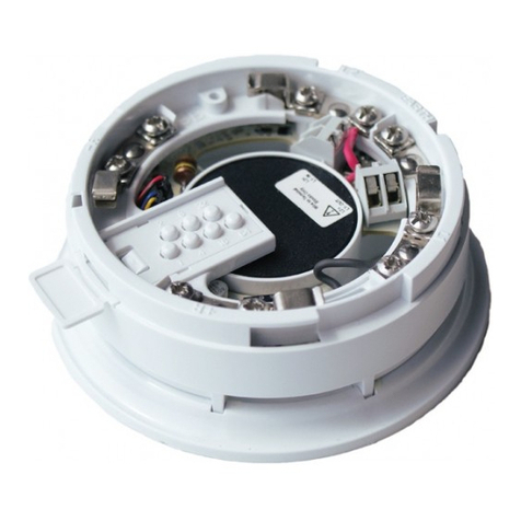
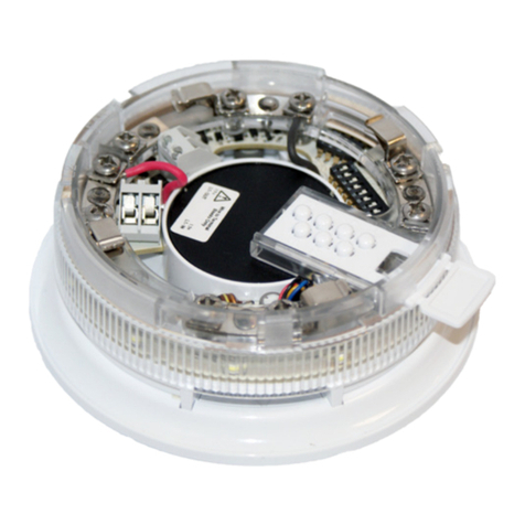
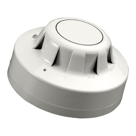
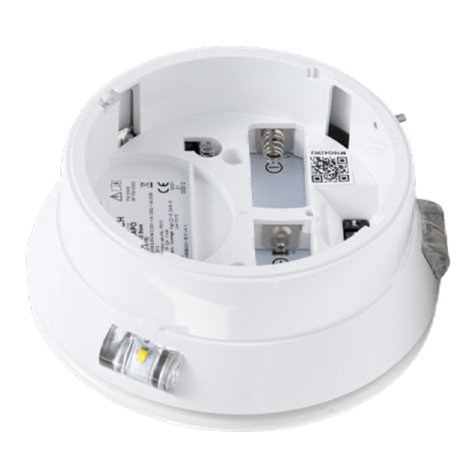
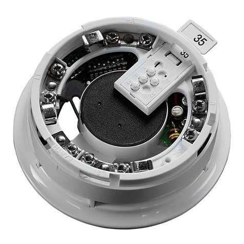
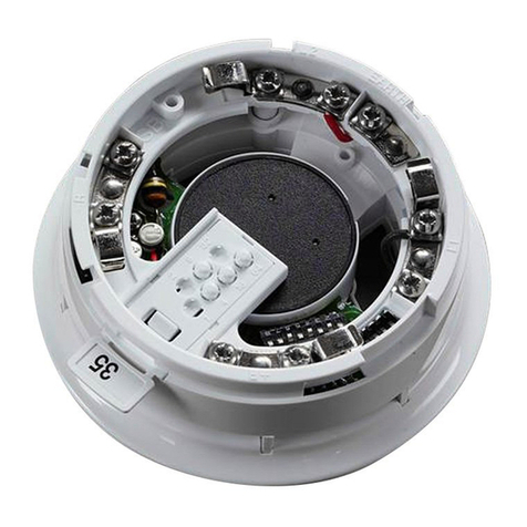
Integrated Base Sounder shown with an optical detector
PP2209/2005/ Issue 1
INTEGRATED BASE SOUNDER
FUNCTION
Apollo Fire Detectors offers a loop-powered
sounder combined with a standard XP95/Discovery
mounting base which is used to signal a fire alarm in
enclosed areas.
FEATURES
The sounder offers:
• two tone ranges 55–75dB and 75–91dB
• synchronisation of ‘alert’ and ‘evacuate’
tones
• individual and group addressing
• available with or without built-in isolator
• unique acoustic self-test
• in addition to the standard tone a slow
whoop tone to Dutch standard NEN2575 is
available
The low tone range is useful in areas such as hos-
pitals where a fire alert is initially intended to warn
staff only. The sounder is set to the high range for
general use.
Synchronisation of tones ensures the integrity of
the signal—tones from different sounders do not
merge into one signal that could be mistaken for a
different tone.
Group addressing is a simple method of alerting an
entire area or group of rooms without delay.
For systems requiring isolators at every point the
built-in isolator saves installation time and cost.
The acoustic self-test means that the sounder
listens to itself when it is switched on. If no sound
is detected a fault signal is transmitted when the
sounder is polled.
ELECTRICAL CONSIDERATIONS
The integrated base sounder is line powered and
needs no external power supply. It operates at
17–28V DC and is polarity-sensitive.
© Apollo Fire Detectors Ltd 2003-2005
PROTECTOR ALARMS (UK) Ltd. TEL No. 020 8761 3771
FAX No. 020 8670 9441
Distributed By
20/22 GIPSY HILL
CRYSTAL PALACE
LONDON.SE19 1NL
email: sales@protectoralarms.com
Website: www.ProtectorAlarms.com
PA
under group address control, it is necessary
to interrogate all devices in the group at their
individual addresses.
SELF TEST
An important safety feature has been incorpo-
rated into the integrated base sounder: when
it is switched on it tests itself by checking the
actual sound output. If no sound is detected
within 5 seconds of the Integrated Base
Sounder being switched on it will transmit an
analogue value of 1 (= sounder fault) when it
is next polled.
This can also be used during commissioning
or periodical maintenance testing. Simply
activate the sounder for at least 5 seconds
and check the control panel for a fault signal.
If none is received, the sounder is working
properly.
PROTOCOL COMPATIBILITY
The sounder will operate only with control
equipment using the Apollo XP95 or Discovery
protocol. The features of the Integrated base
sounder are available only when the sounder
is connected to a control panel with the
appropriate software.
PROTOCOL BIT USAGE
The
output (or forward command) bits
from
the control panel have the following function:
Output bit 2
is used to apply the required
address mode — group addressing or indi-
vidual addressing.
Group addressing is selected by setting
output bit 2 of the individual address to
logic 0 on two or more consecutive cycles
and output bit 2 of the group address to
logic 1 on two or more consecutive poll-
ings. All other output bit 2 combinations
result in the application of the individual
address mode.
Whichever address mode — individual or
group — is applied in any polling, the use
of the other output bits is identical:
When
output bit 1
is set to logic 1 on two or
more consecutive pollings, the ‘alert’ tone
is sounded.
When
output bit 0
is set to logic 1 on two
or more consecutive pollings, the ‘evacu-
ate’ tone is sounded. The sounder will also
operate continuously if both output bit 1
and output bit 0 are set to logic 1 on two or
more consecutive pollings.
TONE FREQUENCY AND VOLUME
CONTROL
The tone frequency of the sounders is pub-
lished in a separate document available for
Apollo Fire Detectors PP2203.
ADDRESSING
The integrated base sounder responds to its
own individual address set with a DIL switch.
It also responds both to a group address, set
by means of a 4-segment DIL switch and to a
pulsed-mode synchronisation address which
is embedded in the unit.
Addresses 1 to 111 are used exclusively for
individual addresses; addresses 112 to 126 are
used for group addressing, while the synchro-
nisation address, to which all units respond,
is ‘0’. Any integrated base sounder on a
loop may be freely assigned to a group. The
address for any group must be chosen from
the range 112–126.
Addresses 112–126 may be used as individual
addresses but only if the 4-segment DIL switch
is not used ie,group addressing is disabled.
If the 4-segment DIL switch were set to any
number other than the default 127, a pre-set
analogue value of 4 would be transmitted to
indicate a fault.
The integrated base sounder is normally
polled by its individual address. It responds
as described below (See
PROTOCOL BIT
USAGE
). If more than one integrated base
sounder is activated it is possible for the
sounders to be out of synchronisation with
the result that the signal in not clear.
To prevent this, it is recommended that the
synchronisation address ‘0’ be sent by the
control panel at regular intervals to align the
internal clock of all sounders. The result is
that the sounders are synchronised with each
other in both ‘alert’ and ‘evacuate’ modes.
NB: Units on two or more loops can be syn-
chronised only if the panel transmits address
’0’ to all loops synchronously.
GROUP ADDRESSING
It may be desirable, in alarm conditions, to
switch more than one integrated base sounder
s i m u l t a n e o u s ly. To enable this, sounders may
be controlled as a group and given a group
address which is common to all sounders in
the group. When a device recognises its group
address, it will process the forward command
bits but it will not return any data to the
control panel on that address. If it is required
to confirm the status of the outputs of devices
The
seven bits
which are then transmitted by
the control panel correspond to the individual
or the group
address (as set on the relevant
DIL switch)
of the device or devices to be
polled. These bits may also be set to zero to
enable the unit to respond to the embedded
address’0’.
After the integrated base sounder has been
addressed by the control equipment, it returns
data if (and only if) its individual address has
been applied. No data is returned when the
group address is polled. The response after
individual addressing will, however, reflect
whatever commands have been set, whether
by individual or by group address mode. The
response is as follows:
The
interrupt bit
is always set to ‘0’.
The
analogue value bits
are set to report a
pre-set analogue value of 16 in quiescent con-
dition and 4 if the group address is incorrectly
set. A value of 1 is reported if the sounder fails
to emit a sound after being switched on.
The
input bits
confirm the execution of the
commands given by the output bits as follows:
Bit 2
is set to logic ‘1’ for group addressing
and to logic ‘0’ if individual addressing has
been applied.
Bit 1
is set to logic ‘0’ when the sounder is
not operated and to logic ‘1’ to indicate that
the sounder has been switched to operate
in ‘alert’ mode.
Bit 0
is set to logic ‘0’ when the sounder
is not operated and to logic ‘1’ when it is
operated in ‘evacuate’ mode. If both bits 1
and 0 are set to ‘1’, this also indicates that
the sounder is in ‘evacuate’ mode.
The
type bits
are used to identify the type
of unit responding. The type code of the
Integrated base sounder is 001 00 (bits 2, 1,
0, 4, 3). Bits 2, 1 and 0 of the type code are
sent immediately after the input bits. The
remaining two bits are sent in the XP95 proto-
col extension.
The integrated base sounder transmits
seven
bits
to confirm its address and then places
one
bit
to indicate that the device is using the XP95
protocol
The
alarm flag
is not placed by the sounder.
The next
two bits
sent are the
extended type
code
bits (bits 4, 3) which, in this case, are ‘00’.
The following
five bits
, extension of the ana-
logue value, are not used by the integrated
base sounder.
The
parity bit
is set to ‘0’ or ‘1’ in the same way
as it is by XP95 detectors.
The
final seven bits
, alarm/interrupt address,
are not used, since the sounder has no alarm
reporting function.
SYNCHRONISATION
Sounders are able to recognise address 0
and synchronise, as in the case of the 100dB
sounder, the Intelligent Base Sounder and
the Sounder Control Unit. This method of
synchronisation depends on the design and
configuration of the control panel. The manu-
facturer of the panel should be consulted to
determine whether this feature is available or
not.
TYPE CODE
The sounder type code is 001 00. (bits 210 43).
MECHANICAL CONSTRUCTION
The integrated base sounder is moulded in
polycarbonate and has stainless steel contacts
that accept solid or stranded cables of up to
2.5mm².
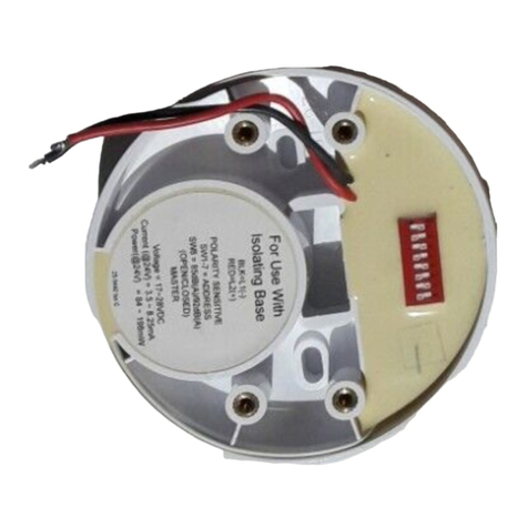
Fig. 1 Address example
1 2 3 4 5 6 7 81 2 3 4 5 6 7 8
O
N
= 0 1 0 1 0 1 0
= Address 42
Individual Address
1 2 3 41 2 3 4
O
N
0 1 1 1 = Address 113
Group Address
0=55-75dB
1=75-91dB
EARTH
–R
+R
L1 OUT L1 IN
L2 L2
Volume control
(Not beacon base)
Remote LED
Group address
setting
Address & tone
setting
–
+
–
+
Position of Isolator LED
Notes
1. The Integrated Base Sounder complies
with EN54–3 when it is used in the
higher tone range.
2. The lower tone range does not comply
with EN54–3 and should not be used as
part of an alarm application.
The purpose of the lower tone range is
to provide a warning in specific cases
such as hospital staff stations.
3. The Integrated Base Sounder is a Type A
sounder, ie, for indoor use only.
Operating voltage 17–28V DC
(polarity sensitive)
Protocol pulses 5–9V
Current consumption at 24V
switch-on surge, <1s 1.2mA
quiescent <1.2mA
sounder operated 50–75dB
or 75–91dB 5mA
Maximum sound output at 90° 91db(A)
Maximum sound output to EN54 83dB(A)
Sound pressure level data is published in
PIN sheet PP2203 available from Apollo
Operating temperature –20°C to +60°C
Humidity (no condensation) 0–95%
IP rating (standard version) 21D
TECHNICAL DATA
DIMENSIONS AND WEIGHT
Part no Description Dimensions Weight
45681-278
45681-291
Sounder
Slow whoop
sounder
115 x 38mm 140g
45681-277
45681-290
Sounder with
isolator
Slow whoop
sounder with
isolator
115 x 38mm 140g
45681-292 White Cap 100 x 9mm 20g
45681-293 Red Cap 100 x 9mm 20g
Output
Bit
Function Bit
usage
Input
Bit
Function Bit usage
2
group
mode
1 = off
0 = on
2groupmode
confirmed
1 = group
0 = individual
1‘alert’
mode
1 = on
0 = off
1‘alert’mode
confirmed
1 = on
0 = off
0‘evacuate’
mode
1 = on
0 = off
0 ‘evacuate’ mode
confirmed
1 = on
0 = off
Table 2 Function of input and output bits
Table 1 Dimensions and weights

Other Apollo Marine Equipment manuals

Apollo Discovery 45681-702 User manual

Apollo

Apollo Discovery 45681-702 User manual

Apollo 45681-300 User manual

Apollo

Apollo 45681-300 User manual

Apollo 45681-278 User manual

Apollo

Apollo 45681-278 User manual

Apollo REACH WIRELESS RW1300-210APO User manual

Apollo

Apollo REACH WIRELESS RW1300-210APO User manual

Apollo REACH WIRELESS RW1300-110APO User manual

Apollo

Apollo REACH WIRELESS RW1300-110APO User manual

Apollo 65 Series User manual

Apollo

Apollo 65 Series User manual

Apollo Discovery 45681-700 User manual

Apollo

Apollo Discovery 45681-700 User manual

Apollo 45681-276 User manual

Apollo

Apollo 45681-276 User manual

Apollo Discovery User manual

Apollo

Apollo Discovery User manual

Apollo 45681-265 User manual

Apollo

Apollo 45681-265 User manual

Apollo MCP1A-R470SF-A071-01IS User manual

Apollo

Apollo MCP1A-R470SF-A071-01IS User manual

Apollo 45681-266 User manual

Apollo

Apollo 45681-266 User manual

Apollo TAS2 SAR BCD Operator's manual

Apollo

Apollo TAS2 SAR BCD Operator's manual

Apollo Discovery Open Area Voice Sounder User manual

Apollo

Apollo Discovery Open Area Voice Sounder User manual

Apollo Smoke Detector XP95 User manual

Apollo

Apollo Smoke Detector XP95 User manual

Apollo REACH WIRELESS RW1500-110APO User manual

Apollo

Apollo REACH WIRELESS RW1500-110APO User manual

Popular Marine Equipment manuals by other brands

E2S IS-pA1 instruction manual

E2S

E2S IS-pA1 instruction manual

Furuno NAVNET 3D MFDBB Software instructions

Furuno

Furuno NAVNET 3D MFDBB Software instructions

Regal-Beloit Velvet Drive LIBERTY Series owner's manual

Regal-Beloit

Regal-Beloit Velvet Drive LIBERTY Series owner's manual

Ziton ZP755BV-4 Installation sheet

Ziton

Ziton ZP755BV-4 Installation sheet

ALBIN PUMP Marine Defroster 9 kW Instructions for use

ALBIN PUMP

ALBIN PUMP Marine Defroster 9 kW Instructions for use

Furuno FI-303 Operator's manual

Furuno

Furuno FI-303 Operator's manual

lumishore LUMI-LINK COMMAND CENTER Setup and user guide

lumishore

lumishore LUMI-LINK COMMAND CENTER Setup and user guide

DIGITAL YACHT Aqua PC Q quick start guide

DIGITAL YACHT

DIGITAL YACHT Aqua PC Q quick start guide

Raytheon Pathfinder ECDIS Operator's manual

Raytheon

Raytheon Pathfinder ECDIS Operator's manual

Digital deep sea 4GXtream Product handbook

Digital deep sea

Digital deep sea 4GXtream Product handbook

JRC JUE-95SA - Operation guide

JRC

JRC JUE-95SA - Operation guide

Raymarine H6 owner's manual

Raymarine

Raymarine H6 owner's manual

Sailor RT5022 VHF DSC Operation manual

Sailor

Sailor RT5022 VHF DSC Operation manual

Ocean Signal EPIRB2 user manual

Ocean Signal

Ocean Signal EPIRB2 user manual

Shockwave ICE Operation & service manual

Shockwave

Shockwave ICE Operation & service manual

ProFurl NC 32 installation manual

ProFurl

ProFurl NC 32 installation manual

Jensen MCD4030 owner's manual

Jensen

Jensen MCD4030 owner's manual

COBHAM SAILOR 6282 user manual

COBHAM

COBHAM SAILOR 6282 user manual

manuals.online logo
manuals.online logoBrands
  • About & Mission
  • Contact us
  • Privacy Policy
  • Terms and Conditions

Copyright 2025 Manuals.Online. All Rights Reserved.