Scanreco G5 Pocket System User manual

Instruction Manual
G5 Rocket Flex/Pocket System
Document: 66068
Revision: A
Language: English

Contents
1 General information.................................................................................. 4
2 Safety information.................................................................................... 5
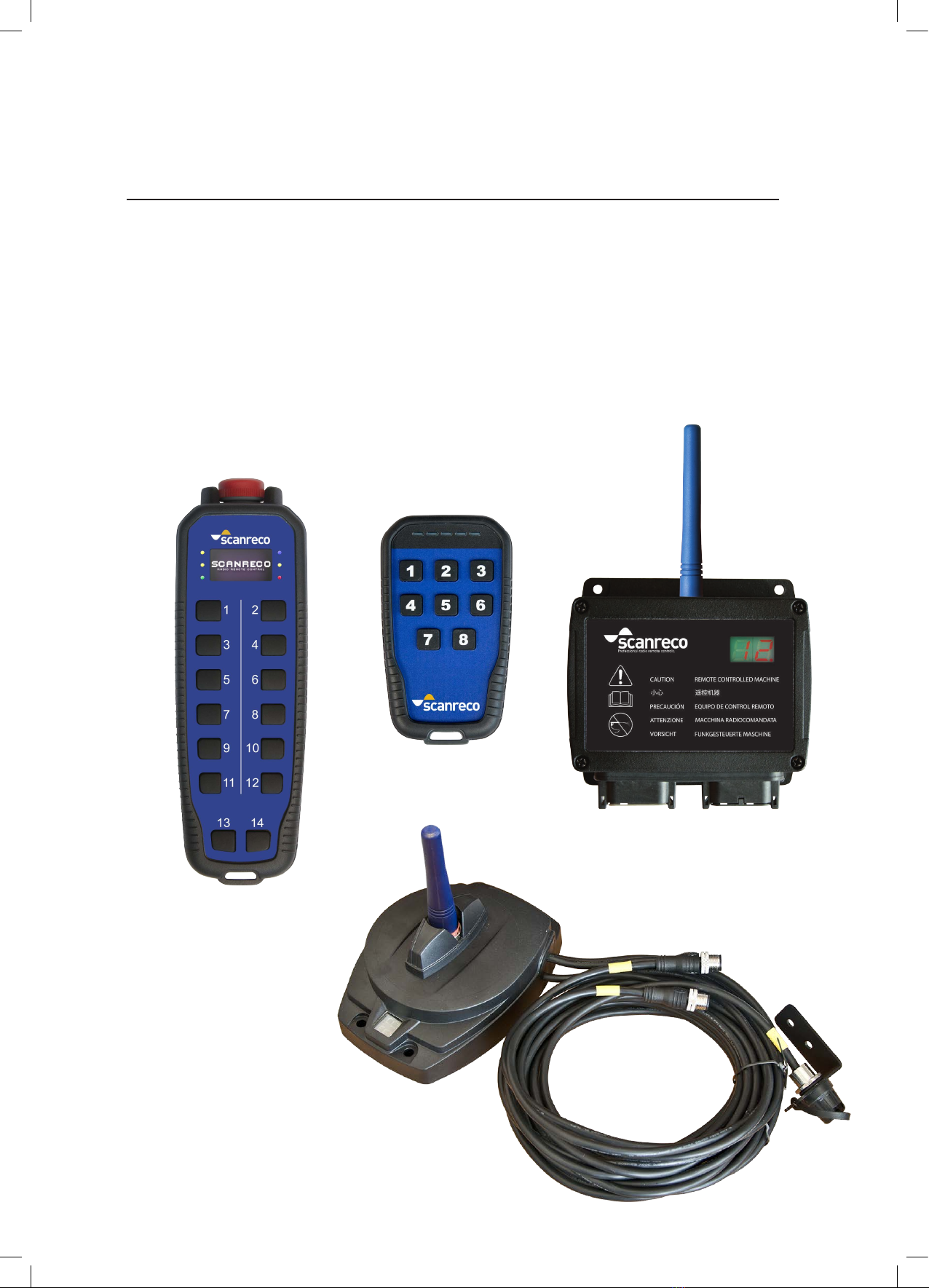
3 System information...................................................................................7
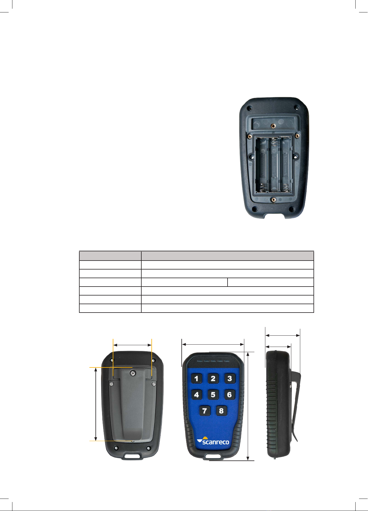
4 G5 Pocket Transmitter.............................................................................. 8
4.1 Product description.................................................................................. 8
4.2 Versions.............................................................
....................................... 9
4.3 Functionality
.............................................................................................9
4.4 Installing/changing battery......................................................................10
4.5 Technical data.......................................................................................... 10
5 G5 Rocket Flex Transmitter......................................................................11
5.1 Product description.................................................................................. 11
5.2 Versions...........................................................................
......................... 12
5.3 Functionality..............................................................................
............... 12
5.4 Installing/changing battery......................................................................13
5.5 Technical data.......................................................................................... 14
5.6 Battery charger......................................................................................... 15
6 G5 Receiver............................................................................................... 16
6.1 Product description.................................................................
................. 16
6.2 Versions.....................................................................................
................17
6.3 Functionality..............................................................................
................17
6.4 Technical data G5 M19........................................................................... 18
6.5 Technical data G5 R5 & R10................................................................... 19
6.6 Technical data G5 CAN............................................................................ 20
6.7 Receiver dimensions................................................................................21
7 Radio information.....................................................................................
22
8 Installation recommendation................................................................... 23
8.1 General information................................................................................. 23
8.2 Assembly of the Receiver.........................................................................23
8.3 Torque values........................................................................................... 25
9 Startup and LED indication...................................................................... 26
10 Programming.............................................................................................27
10.1 General description................................................................................. 27
10.2 Safe pairing mode....................................................................................27
10.3 Set to factory defaults.............................................................................. 27
11 Product care.............................................................................................. 28
12 Troubleshooting.......................................................................................
29
12.1 General..................................................................................................... 29
12.2 Troubleshooting.....................................................................
................... 29
12.3 Transmitter test mode...................................................................
...........30
13 Spare parts................................................................................................ 31
14 Accessories...............................................................................................32
15 Programmed assignment template......................................................... 33
2/33

Attribute Information
Document Type Instruction Manual
Title SCANRECO G5 Rocket Flex/Pocket System
Document No. 66068
Language English
Release date 2016-01-25
Original English
Release date (original) 2016-01-25
Author SCANRECO
Company SCANRECO AB, SWEDEN
Revision Date Note
A 2016-01-25 First release
LED Light Emitting Diode
EMC Electromagnetic Compatibility
ISM Industrial, Scientic and Medical (radio band)
MOSFET Metal Oxide Semiconductor Field Effect Transistor
Document information
Revision history
Abbrevations
All rights reserved
Design, equipment, technical data and specications are subject to change or improvement
without prior notice. The text in this instruction manual, or any part of it may not be modied in
any form or by any means, including electronic, mechanical, photocopying, recording, storage
in an information retrieval system, or otherwise, without prior written permission of SCANRECO
AB, SWEDEN.
3/33

1 General information
This instruction manual describes the SCANRECO G5 Pocket & G5 Rocket Flex system, this
instruction manual should be seen as a complement to the instruction manual for the application
which the SCANRECO G5 Rocket Flex is intended to operate with.
The SCANRECO G5 system is a complete remote control system for mobile and stationary
applications where durability and functionality is in high demand, the SCANRECO G5 system
offers the system installer a exible and congurable remote control system.
To ensure the safety of the remote control system and the application you should carefully study
this instruction manual. This will ensure that you are familiar with the system and ready to use it
in it’s intended application.
Notice to reader:
TO THE SYSTEM INSTALLER:
Pay special attention to the chapters Safety Information, Installation recommendations and
Programming.
TO THE OPERATOR:
Pay special attention to the chapters Safety Information, Product description and
Product Care.
TO THE SERVICE TECHNICIAN:
Pay special attention to the chapters Safety Information, Product Care, Trouble Shooting and
Spare Parts.
The following labels are used throughout this document to create awareness about important
recommendations or warnings. It is important that these recommendations or warnings are
considered by the installer, operator and service personnel.
IMPORTANT!
This information must be followed, potential hazards for the operator and environment if
instructions are not followed.
ATTENTION!
General recommendation. If not followed may cause the system not to perform at full capacity.
NOTE!
General notice.
4/33

2 Safety information
READ THE SAFETY INSTRUCTIONS CAREFULLY BEFORE INSTALLING,
CONFIGURATING AND OPERATING THIS PRODUCT!
MAKE SURE THAT YOU, THE OPERATOR OR SERVICE TECHNICIAN, HAVE FULLY
UNDERSTOOD THE SAFETY INSTRUCTIONS BEFORE PROCEEDING
IMPORTANT!
The system installer is responsible for producing an instruction manual for the application
where the SCANRECO G5 system has been installed and intended to control.
The system installer is responsible for producing a product approval, if such is required, for the
application where the SCANRECO G5 system has been installed.
Prior to operation, the system installer is required to train the operator on all functions available
using the SCANRECO G5 system.
Prior to operation, the system installer is required to inform the operator of all potential
hazardous situations that may appear when operating the application with the SCANRECO G5
system.
The system installer must take into account the specic installations instructions declared in
this instruction manual.
Due to the unlimited variety of applications (cranes, machines, objects, vehicles and other
equipment) on which the remote control system is used, and the numerous standards which
are frequently the subject of varying interpretation, it is impossible for the personnel at
SCANRECO to provide expert advice regarding the suitability of a given remote control for a
specic application. It is the responsibility of the purchaser and system installer to determine
the suitability of any SCANRECO remote control product for an intended application and to
ensure that it is installed and guarded in accordance with all country, federal, state, local, and
private safety and health regulation, codes, standards and the SCANRECO instructions in this
document.
If the SCANRECO G5 system will be used in a safety critical application, the purchaser / system
installer must undertake appropriate testing and evaluation of the nal application to prevent
injury to the end user.
SCANRECO does not take responsibility for any damage or injury.
Unauthorized tampering with any of the products will automatically void the SCANRECO
guarantee and product responsibility.
2.1 General
5/33

2.2 Pre-operational
Prior to operation, the operator must ensure that: he/she:
• is fully trained by the system installer in proper use of the application and knows all
functions available in the SCANRECO G5 system.
• is responsible to ensure that non-qualied personnel never gains control of the
SCANRECO G5 system.
• has fully understood this instruction manual.
• has fully understood the instruction manual given by the system installer.
• is well aware of the positioning of the emergency stop arrangements.
• uses the correct transmitter with the correct receiver unit.
• has at all times full view of the work area where the application is used.
• always keeps the SCANRECO G5 system deactivated if not used.
• never leaves the SCANRECO G5 system unsupervised.
• stores the SCANRECO G5 system in such a way that unauthorized personnel cannot gain
control of it.
• on a daily basis ensure that all safety related functions and emergency stop functions works
accordingly(or immediately if suspicion of malfunction).
• always report faults that may have appeared during operation to the system installer.
• is aware of, and obey, any local rules applied regarding operation of the application that
the SCANRECO G5 system is operating.
In order to ensure safety of the operator, bystanders and the machine, the user should study
and learn all provided instructions regarding how to use the SCANRECO G5 system as well as all
safety instructions and the location of all emergency stop controls. This will enable the user to
quickly get familiar with the new remote control system and how to safely utilize it.
The operator must understand and follow the below instructions at all times!
6/33

3.1 System overview
The SCANRECO G5 system system has been especially developed for hydraulically driven mobile
machinery. The system is a digital remote control system based on advanced microprocessor
technology which can cope with the roughest of environments. The system is highly resistant
against electromagnetic and radio frequency radiation. The G5 system is comprised of a Pocket
or Rocket Flex Transmitter with pushbuttons. The Receiver provides the connection points for
connecting to the electro-hydraulic valves or controller. Digitally coded control information is
sent in both directions via radio between the Transmitter and the Receiver.
3 System information
G5 Pocket
G5 Rocket Flex
G5 Receiver M19
G5 Receiver CAN
7/33

4.1 Product description
The G5 Pocket Transmitter is a light weight, impact and water resistant handheld unit
equipped with up to eight pushbuttons. It has ve congurable Light Emitting Diodes (LED)
for machine and status feedback. The buttons and the LED’s can be congured for a variety
of different operations. The unit is powered with 3 standard AAA batteries and the backside
has a belt clip for convenient attachment on the operator’s belt.
4 G5 Pocket Transmitter
LED 1
Button 1
Button 4
Button 3
Button 6
Button 2
Button 5
Button 7 Button 8
LED 2 LED 3 LED 4 LED 5
Belt clip Battery compartment
(Belt clip removed)
Label
8/33

ONIN OUT
OFF
1 2 3 1
4
2
5
3
6
1
4
7
2
5
8
3
6
1
4
ON
2
5
OFF
3
6
1
4
2
5
3
6
STOP
Fn
Model Button conguration
G5 P3 3 one-step pushbuttons
G5 P4 4 one-step pushbuttons
G5 P6 6 one-step pushbuttons
G5 P8 8 one-step pushbuttons
The G5 Pocket Transmitter comes in the following versions:
The G5 Pocket systems are normally delivered with the default settings. Default start button
is button number 7 and default stop button is button number 8. Button number 1-6 has a
momentary activation of output 1-6. (Pocket Transmitters with 6 buttons or less needs to be
congured before they can be started.) If any other functions are required they need to be
congured prior to operation. The pushbuttons are easily programmed to activate any output
or function. Button denitions include momentary, interlocked or latched output. Please have
a look at chapter 15 if any description of the functionality is declared.
There are two ways of conguring the functionality. With On-Site programming or with WinSCI
software. Neither of them are described in this manual as it is intended for the installer and
end user. Please contact Scanreco in case of programming is required.
Another Pocket or Rocket transmitter can be congured to work as a repeater to extend the
working range. Please contact Scanreco in case of repeater function is required.
G5 P3 G5 P4 G5 P6 G5 P8 G5 P8 G5 P8
The models may have the different printed symbols on the buttons, colors, scripts,
pictures etc.
4.2 Versions
4.3 Functionality
Label
9/33

4.4 Installing/changing battery
The G5 Pocket Transmitter is equipped with 3 standard AAA cell batteries; to change
batteries follow the instructions below
1. Remove the belt clip by unscrewing the top middle screw.
2. Unscrew the three screws holding the lid.
3. Remove the batteries.
4. Remove all dirt/dust to ensure no water can enter the unit.
5. Insert new batteries, mind the polarity!
6. Reassemble the lid and the belt clip.
Tighten the screws according to chapter 8.3.
38,8mm
75,2mm
38mm (1,5 in)
27mm
115mm (4,5 in)
67mm (2,6 in)
Attribute Information
Housing material Plastic PC-ABS
IP-class IP67
Ambient temperature -25˚C to +70˚C -15ºF to 160ºF
Supply 3 x AAA battery
Operating time Several months (depending of usage and application)
Weight 160 g (0,35lb.) including battery
4.5 Technical data
10/33

Belt clip Battery compartment
(Belt clip removed)
Battery compartment
(Lid removed)
5.1 Product description
5 G5 Rocket Flex Transmitter
The G5 Rocket Flex Transmitter is a light weight, impact and water resistant handheld unit
equipped with up to fourteen ON/OFF function pushbuttons. The pushbuttons can have
a two-step function. It has ve congurable Light Emitting Diodes(LED) for machine and
status feedback as well as a charge indication LED. A 128x64 pixel monochrome OLED
display is optional. The buttons and the LED’s can be congured for a variety of different
operations. The unit is powered with three re-chargeable AA batteries which is included
separately in the delivery. The associated battery charger is recommended to be used
with the unit. The backside has a belt clip for convenient attachment on the operator’s
belt.
Charge indication
Stop button
Button 1 Button 2
Button 3 Button 4
Button 5 Button 6
Button 7 Button 8
Button 9 Button 10
Button 11 Button 12
Button 13
Label
Button 14
Led 3
Led 2 Led 4
Led 1 Led 5
11/33

The G5 Rocket Flex Transmitter comes in the following versions:
G5 RF 14 G5 RF 14 Display
Model Button conguration
G5 RF 14A 12x2-step, 2x1-step pushbuttons
G5 RF 14B 14x1-step pushbuttons
G5 RF 14E 14x2step pushbuttons
G5 RF 14A Display 12x2-step, 2x1-step pushbuttons
G5 RF 14B Display 14x1-step pushbuttons
G5 RF 14E Display 14x2-step pushbuttons
5.2 Versions
5.3 Functionality
The G5 Rocket systems are normally delivered with the default settings. Default start button
is button number 7(red stop button must be released) and default stop button is button
number 8 or the red stop button. Button number 1-6 has a momentary activation of output
1-6 (button 9-14 are not mapped to any output). If any other functions are required they
need to be congured prior to operation. The pushbuttons are easily programmed to activate
any output or function. Button denitions include momentary, interlocked or latched output.
Please have a look at chapter 15 if any description of the functionality is declared.
There are two ways of conguring the functionality. With On-Site programming or with WinSCI
software. Neither of them are described in this manual as it is intended for the installer and
end user. Please contact Scanreco in case of programming is required.
Another Pocket or Rocket transmitter can be congured to work as a repeater to extend the
working range. Please contact Scanreco in case of repeater function is required.
12/33

5.4 Installing/changing battery
The G5 Rocket Flex Transmitter requires 3 re-chargeable AA cell batteries. Batteries
are included in the delivery but needs to be installed, follow the instructions below:
1. Remove the belt clip by unscrewing the top middle screws.
2. Unscrew the four screws holding the lid.
3. Remove the batteries.
4. Remove all dirt/dust to ensure no water can enter the unit.
5. Insert new batteries, mind the polarity!
6. Reattach the lid and the belt clip. Tighten the screws.
0,8 Nm
IMPORTANT!
If using standard non rechargeable batteries, do not use the charger.
0,8 Nm
123
13/33

69mm (2,7 in)
Attribute Information
Housing material Plastic PC
IP-class IP 65
Ambient temperature -25 ºC to 55 ºC -15ºF to 130ºF
Supply 3 x AA battery
Operating time Without display: up to 120 hours of operation
With display: up to 40 hours of operation
(depending on usage of LED and display)
Weight 400g (0,88lb.) including battery
ISO-13849 for stop function Category 3, PL d
48mm (1,9 in)
42mm (1,7 in)
213mm (8,4 in)
35mm (1,4 in)
84mm (3,3 in)
5.5 Technical data
14/33

Attribute Information
Power Supply 9-36 VDC
IP-class IP 21
Overload Protection Yes (still recommended to use a 3A fuse)
Current consumption <15 mA (idle)
200-900 mA during charging (depending on supply voltage)
Charging time 2 hours and 20 minutes
Cable length 1,8 m
Assembly 1/4” UNC (Suited for RAM-Mount Size B)
Ambient Temperature -20°C to +70°C ~ -4°F to +160°F
Charging temperature +5°C to +45°C ~ -41°F to +113°F
Dimensions 70 x 35,5 x 113 mm 2,75 x 1,4 x 4,45 in
Weight 70 g ~ 0.2 lbs.
5.6 Battery charger
The battery charger also works as a holder for the Rocket Flex. The charger can be assembled
on the machine with a 1/4” UNC screw, same as RAM-Mount Size B holders. While the Rocket
Flex is charging the blue LED is ashing. When charging is nished, the blue LED is lit. The
charger is delivered with a 1.8 meter cable with open wires.
IMPORTANT!
During charing, the ambient temperature needs to be between +5° and +45°C.
~ -41°F to +113°F
35,5mm (1,4 in)
70mm (2,75 in)
113mm (4,45 in)
15/33

6 G5 Receiver
6.1 Product description
The G5 Receiver is manufactured in plastic and is provided with contacts for connection of
power supply and electro-hydraulic valves. Depending on the version the G5 Receiver can
either be equipped with MOSFET outputs/inputs and Deutsch connectors, relay outputs
with spring terminal block or CAN-Bus output.
Since the Receiver can be exposed to very tough environments, the box is encapsulated to
give protection from damp, heat, cold, dust, vibration and corrosive environments.
The Receiver has short circuit proof inputs and outputs and has protection against
polarity reverse, over-voltage, large incoming voltage transients and electromagnetic and
radio interference.
Label
16/33

G5-M19A G5-R5/R10 G5-CAN
Model Functions
G5-M19A Two 12-pin Deutsch connectors. 19 Digital MOSFET outputs whereof
14 can be congured as digital inputs.
G5-R5 Two cable glands. 5 Relay outputs.
G5-R10 Two cable glands. 10 Relay outputs.
G5-CAN CAN-Bus output
6.2 Versions
The G5 Receiver exists in different versions. The main difference between the version types
is the output type which can be either MOSFET output, Relay output or CAN-Bus output.
Versions with MOSFET output have two 12-pin Deutsch connectors while versions with relay
output have cable glands with spring terminal block. The CAN version have cables with M12
connectors.
The G5 system is required to be congured prior to operation, refer to programming section
10 in this document for further information.
6.3 Functionality
17/33

6.4 Technical data Receiver G5 M19
1
12
2
11
3
10
4
9
5
8
6
7
7
6
8
5
9
4
10
3
11
2
12
1
A1 = Output/input 16
A2 = Output/input 15
A3 = GND
A4 = Output/input 14
A5 = Estop
A6 = Power Supply +
A7 = Output 1
A8 = Output 2
A9 = Output 3
A10 = Output 5
A11 = Output 4
A12 = Output/input 6
B1 = Output/input 7
B2 = Output/input 8
B3 = Output/input 9
B4 = Output/input 10
B5 = Output/input 11
B6 = Output/input 12
B7 = RS232 TX
B8 = RS232 RX
B9 = Output/input 13
B10 = Output/input 17
B11 = Output/input 18
B12 = Output/input 19
Attribute Information
Power Supply 9-36 VDC
IP-Class IP67
Connector Interface 2 x 12 pin Deutsch connectors
Programming interface RS232
Overload Protection Yes, maximum 36 VDC
Current consumption <30 mA (idle), 60 mA + External loads in operation
Digital Inputs 14 (can also be used as digital outputs) Do not exceed supply voltage.
Digital Outputs 19 MOSFET driven outputs, Short circuit proof, overload protected.
E-Stop Output Active when system is operational, short circuit proof, overload pro-
tected.
Max output load 3A/output, 5A/bank, 10A/system
Bank 1 2 3 4 5 6 7 8 9 10
Output 1,Estop 2,3 4,5 6,16 7,9 8,10 11,12 13,17 18,19 14,15
Housing screw torque 0.8 Nm
Ambient Temperature -25°C to +70°C ~ -15°F to +160°F
Weight 0,5 Kg ~ 1.10 lbs
18/33

6.5 Technical data Receiver G5 5R & R10
ATTENTION!
After assembly make sure you tighten the housing screws with 0,8 Nm
to avoid any water ingression.
A1 = GND
A2 = Power Supply +
A3 = REL1, common
A4 = REL1, normally closed
A5 = REL1, normally open
A6 = REL2, common
A7 = REL2, normally closed
A8 = REL2, normally open
A9 = REL3, common
A10 = REL3, normally closed
A11 = REL3, normally open
A12 = REL4, common
A13 = REL4, normally closed
A14 = REL4, normally open
A15 = REL5, common
A16 = REL5, normally closed
A17 = REL5, normally open
B1 = REL6, common
B2 = REL6, normally closed
B3 = REL6, normally open
B4 = REL7, common
B5 = REL7, normally closed
B6 = Rel7, normally open
B7 = REL8, common
B8 = REL8, normally closed
B9 = REL8, normally open
B10 = REL9, common
B11 = REL9, normally closed
B12 = REL9, normally open
B13 = REL10, common
B14 = REL10, normally closed
B15 = REL10, normally open
171
115
Attribute Information
Power Supply 9-36 VDC
IP-Class IP65
Connector Interface Spring terminal block (tool free assembly)
Programming interface RS232
Overload Protection Yes, maximum 36 VDC
Current consumption <30 mA (idle)
60 mA + External loads in operation
Digital Outputs 5 or 10 digital outputs. Each output (relay) needs to be supplied with power
through the terminal connector. External fuse is recomended.
Not short circuit proof, not overload protected, max. 5 Ampere load/output.
Each output is electrically isolated.
Cable Glands 2, dimension 8-13mm (0,31-0,51 in.)
Housing screw torque 0.8 Nm
Ambient Temperature -25°C to +70°C ~ -15°F to +160°F
Weight 0,35 Kg ~ 0.77 lbs
Attribute Information
Power Supply 9-36 VDC
IP-Class IP67
Connector Interface 2 x 12 pin Deutsch connectors
Programming interface RS232
Overload Protection Yes, maximum 36 VDC
Current consumption <30 mA (idle), 60 mA + External loads in operation
Digital Inputs 14 (can also be used as digital outputs) Do not exceed supply voltage.
Digital Outputs 19 MOSFET driven outputs, Short circuit proof, overload protected.
E-Stop Output Active when system is operational, short circuit proof, overload pro-
tected.
Max output load 3A/output, 5A/bank, 10A/system
Bank 1 2 3 4 5 6 7 8 9 10
Output 1,Estop 2,3 4,5 6,16 7,9 8,10 11,12 13,17 18,19 14,15
Housing screw torque 0.8 Nm
Ambient Temperature -25°C to +70°C ~ -15°F to +160°F
Weight 0,5 Kg ~ 1.10 lbs
N.C.
Power supply
Common
Common
REL 1
REL 2
N.O.
N.C.
N.O.
NOTE!
Common pin needs to be wired. Normally, power supply needs to
be connected according to the schematic to the right.
19/33

6.6 Technical data G5 Receiver CAN
Attribute Information
Power Supply 9-36 VDC
IP-Class IP67
Connector Interface 3x M12 connectors with 3 meter cable each, see specication below
Programming interface RS232
Overload Protection Yes, maximum 36 VDC
Current consumption Idle: 65 mA (at 24V)
Operational: 100 mA + External loads in operation (at 24V)
Digital Outputs Short circuit proof, overload protected, max. 2,7 Ampere load
DV2 is active when radio link is active.
Safety loops Feed Loop-In with power supply. Once radio link is established, Loop-Out goes
high. Short circuit proof. Max 2,7 Ampere load.
CAN bus CAN Open
Ambient Temperature -25°C to +70°C ~ -15°F to +160°F
Weight 1,2 Kg ~ 2.6 lbs
Connection
Pin no. Colour /Function
1 Brown / Not used
2White / Power supply + 12/24VDC
3 Blue / GND / CAN_GND
4 Black / CAN_HIGH
5 Grey / CAN_LOW
Connection
Pin no. Colour /Function
1 Brown / Not used
2 White / GND
3 Blue / RS 232 TX
4 Black / RS 232 RX
5 Grey / Not used
Connection
Pin no. Colour /Function
1Brown / DV2+
2 White / LOOP1_OUT
3 Blue / LOOP1_IN
4 Black / LOOP2_OUT
5 Grey / LOOP2_IN
Cable C
Cable B
Cable A
2
2
1
1
3
3
5
5
4
4
5-pole
M12 connector
5-pole
M12 connector
male
male
1 2
5
4 3
5-pole
M12 connector
female
20/33
Other manuals for G5 Pocket System
2
This manual suits for next models
5
Table of contents
Other Scanreco Remote Control manuals