INSTALLATION MANUAL
1) GENERAL INFORMATION
TheDEIMOSAC A600actuatorishighlyversatileintermsofinstallation
options due to the extremely low position of the pinion, the actuator’s
compact nature and the height and depth adjustment features it oers.
Manual emergency operation is extremely easy to perform using just
a release lever.
Stopping at end of travel is controlled by electromechanical micros-
witches.
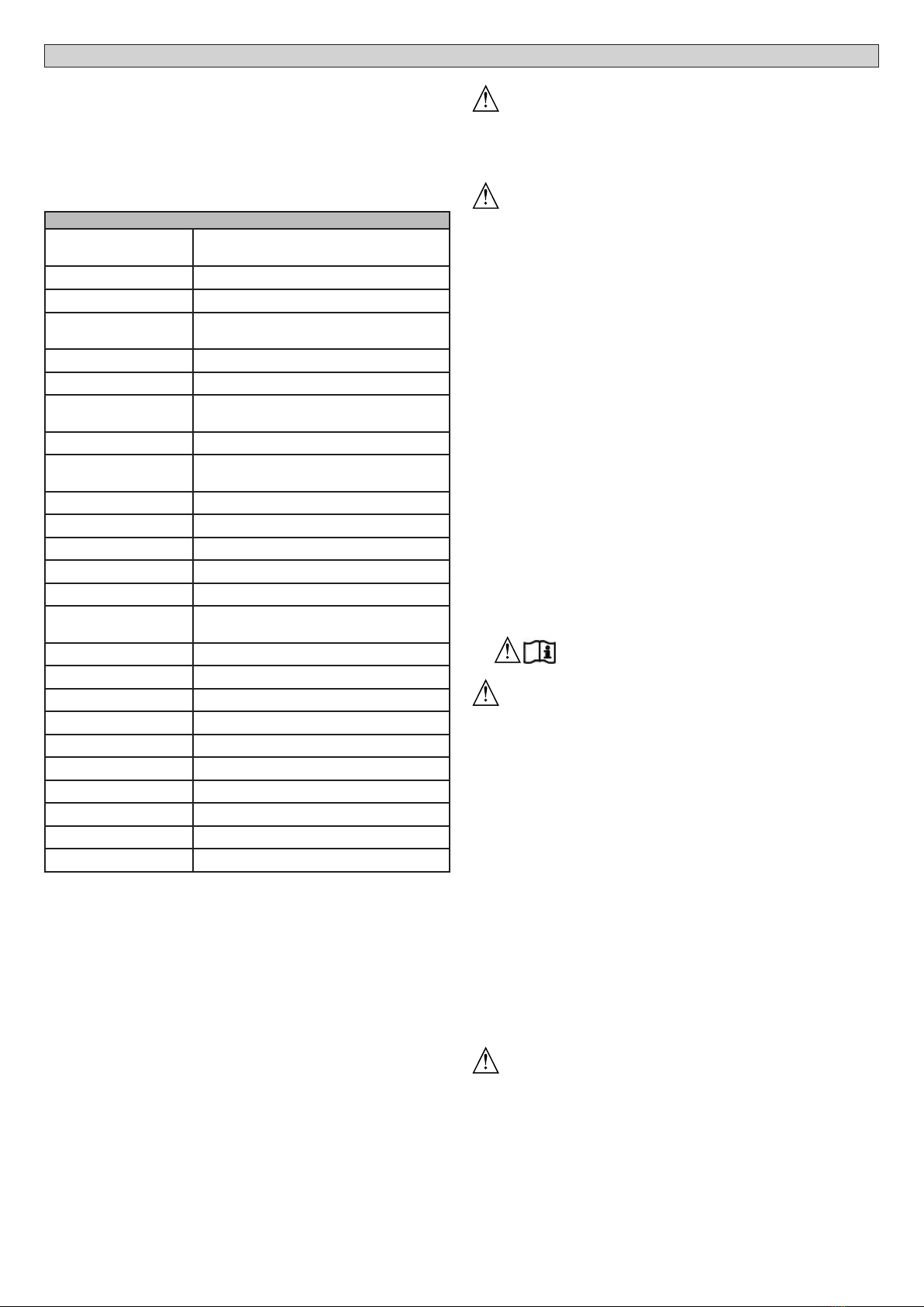
2) TECHNICAL SPECIFICATIONS
Power supply 110 - 120V 60Hz
220-230V 50/60 Hz(*)
Motor revolutions 1400 min-1
Power input 400 W
Capacitor 14 µF (220-230V)
50 µF (120V)
Thermal protection 150° C
Insulation class F
Pinion module (stan-
dard) 4mm (14 teeth)
Leaf speed (standard) 9 m/min
Max. leaf weight - stan-
dard**
600kg (≈6000N)
Pinion module (fast) 4mm (18 teeth)
Leaf speed (fast) 11m/min
Max. leaf weight - fast** 370kg (≈3700N)
Max. torque 18Nm
Reduction ratio 1/30
Impact reaction See paragraph “APPLICATION OF ACTIVE
PROTECTION DEVICES”
Lubrication Lifetime greased
Manual operation Lever-operated mechanical release
Type of use Residential
Control unit SHYRA AC SL
Environmentalconditions
from -20°C to + 55°C
Protection rating IP24
Noise level <70dBA
Operator weight 8,1 kg (≈81N)
Dimensions See Fig. G
Maximum cycle
5 cycls/h with 50s operation
(*) Special supply voltages to order.
** There are no minimum or maximum dimension restrictions for the
guided part that can be used.
3) TUBE ARRANGEMENT Fig.A
Installtheelectricalsystemreferringtothestandardsinforceforelectrical
systems CEI 64-8, IEC 364, harmonization document HD 384 and other
national standards.
4) PREPARATION FOR MOTOR MOUNTING FIG.B
Make a hole in the ground to accommodate the concrete pad, with an-
chors embedded in the base plate for fastening the gearbox assembly,
keeping to the distances featured in FIG.B.
5) REMOVING THE COVER Fig.C
• Unscrewtherelevanttwofrontscrews(FIG.C-rif.1).
• Pushasillustrated(FIG.C-rif.2-rif.3)toreleasethecoverfromthetwo
rear blocks (FIG.C - rif.3A e FIG.C - rif.3B).
• Liftthecover(FIG.C-rif.4).
6) MOUNTING THE MOTOR FIG.D
7) MOUNTING DRIVE ACCESSORIES FIG.E-E1
Recommended rack types (FIG.H)
8) RACK CENTRING WITH RESPECT TO PINION FIG.I-J1-K
DANGER -Welding must be performed by a competent person
issued with the necessary personal protective equipment as
prescribed by the safety rules in force FIG.L.
9) FASTENING LIMIT SWITCH BRACKETS FIG.F
10) STOPS FIG.L
DANGER -The gate must be tted with mechanical stops to halt
its travel both when opening and closing, thus preventing the
gate from coming o the top guide. Said stops must be fastened
rmlytotheground,afewcentimetresbeyondtheelectricstoppoint.
Note: the safety edge (Fig. L ref.1) must be installed so that it is not
triggered by the mechanical stops.
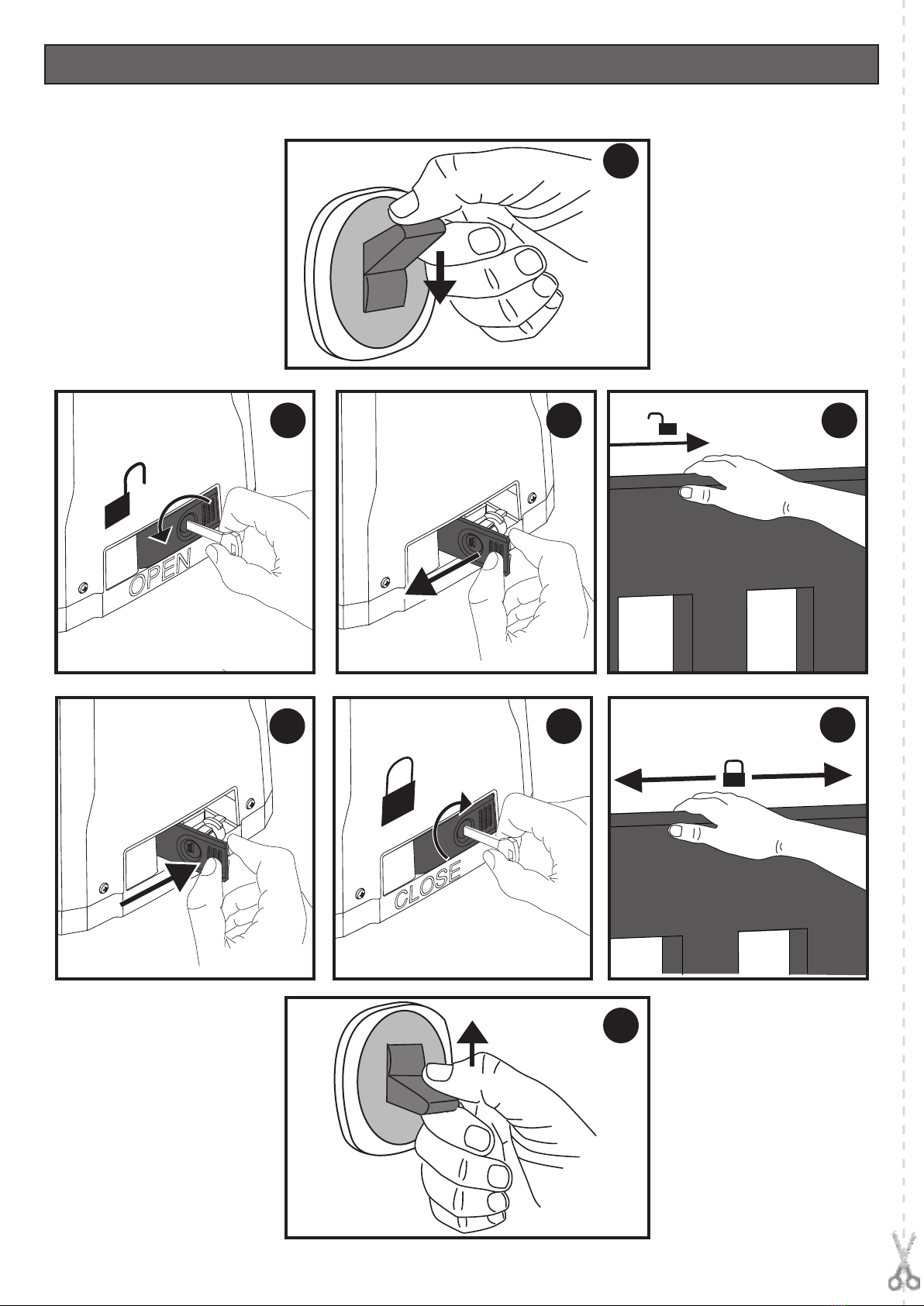
11) MANUAL RELEASE (See USER GUIDE -FIG.3-).
Warning Do not JERK the gate open and closed, instead push it
GENTLY to the end of its travel.
12) TERMINAL BOARD WIRING Fig. M
Remove the board cover releasing it as per the instructions (Fig. M1-M2-
M3).
Once suitable electric cables have been run through the raceways and
the automated device’s various components have been fastened at the
predetermined points, the next step is to connect them as directed and
illustratedinthediagramscontainedintherelevantinstructionmanuals.
Connect the live, neutral and earth wire (compulsory).The mains cable
mustbeclampedinthe relevantcablegland(FIG.M-ref.X)and while the
earth wire with the yellow/green-coloured sheath must be connected
in the relevant terminal (FIG.M-ref.Y).
WARNINGS - When performing wiring and installation, refer to the
standards in force and, whatever the case, apply good practice princi-
ples. Wires carrying dierent voltages must be kept physically separate
from each other, or they must be suitably insulated with at least 1mm
of additional insulation.
Wires must be secured with additional fastening near the terminals,
using devices such as cable clamps. All connecting cables must be kept
far enough away from dissipaters.
13 SEETHECONTROLUNIT’SUSERGUIDEFORINFOR
MATION ON SETTING THE MOTOR’S PARAMETERS
DANGER – The torque adjuster must be calibrated before the
automation becomes operational.
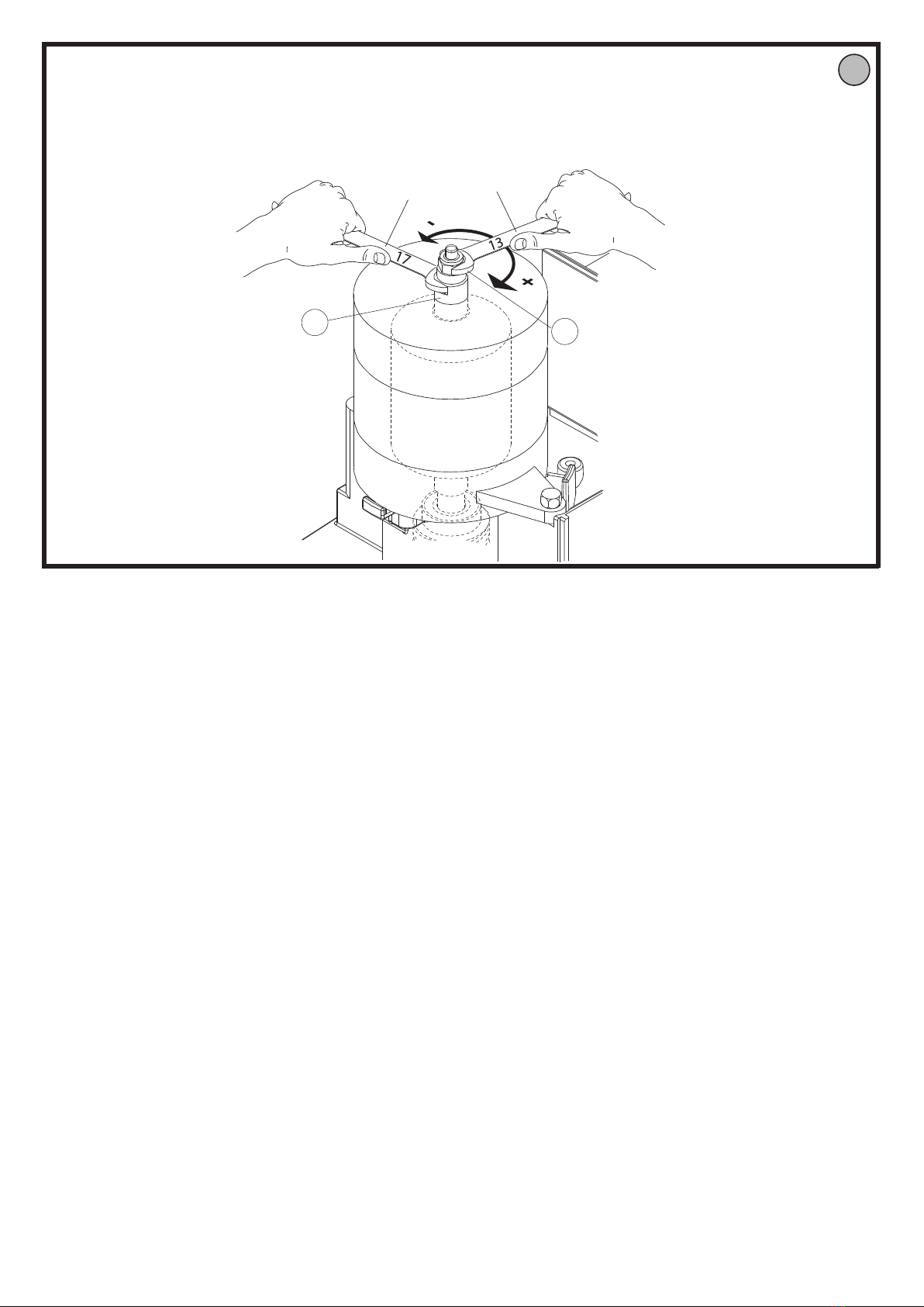
14) TORQUE ADJUSTMENT
The adjustment must be carried out in compliance with the safety re-
gulations in force. To this end, proceed as follows:
• Disconnectthepowersupply.
• Removethexingscrewsofthegearmotorcasing.
•
With the seventeen spanner NOT supplied, block the drive shaft (Fig.
N. – ref.“A”).
WithanotherthirteenspannerNOTsupplied,screwintheself-locking
nut (Fig. N – ref. “B”) to increase the torque, or loosen it to decrease
the torque.
• Replacethegearmotorcasingandxitwiththescrews.
15) APPLICATION OF ACTIVE PROTECTION DEVICES
If the motor is not manned, install type“C”or“E”safety devices according
to EN12453 and in compliance with EN12978. If the dangerous edges
of the door are protected with active strips, check the declared data are
compatible with the driving unit. In particular check that:
a. the extra travel exceeds 30 mm;
b. the maximum speed exceeds 9m/min (11m/min for the fast version);
c. the temperature range is at least -20°C +55°C;
d. the response time is compatible with the motor;
e. the strip is suitable to the type of edge to be protected;”
ATTENTION: Vérier que la valeur de la force d’impact mesurée
aux endroits prévus par la normeEN 12445, est inférieure aux
indications de la norme EN 12453.
WARNING! Incorrect settings can result in damage to property and
injury to people and animals.
20 - DEIMOS AC A 600
D812460 00100_02