Schaudt LT 100 User manual

ESchaudt GmbH, Elektrotechnik und Apparatebau, Planckstraße 8, 88677 Markdorf, Germany, Tel. +49 7544 9577-0, Fax +49 7544 9577-29, www.schaudt--gmbh.de
8310068 BA / EN Date: 19.07.2018
Operating Instructions
Operator and control panel LT 100
Table of contents
1 Introduction 2............................................
2 Application and function 2.................................
3 Operation 3..............................................
3.1 Layout 3................................................
3.2 Starting up 4.............................................
3.3 Switching on 4...........................................
3.4 Checking battery voltage 4.................................
3.5 Checking tank levels 6....................................
3.6 Troubleshooting and remedies 6............................
3.7 Switching off 7...........................................
3.8 Closing down the system 8................................
4 Maintenance 8...........................................
Appendix 9..............................................

Operating Instructions Operator and control panel LT 100
2Date: 19.07.2018 8310068 BA / EN
1 Introduction
This instruction manual contains important information for the safe operation
of equipment supplied by Schaudt.
The operating instructions should always be kept in the vehicle.
YATTENTION!
Failure to comply with the sign may result in damage to equipment or other
connected loads.
2 Application and function
The LT 100 control panel is the central console for electroblock EBL ... /
CSV ... supplying all 12V consumers in the electrical system on board the
motorhome. It is usually installed in an easily accessible place high up near
the door of the vehicle.
+--
+--
LT 100
control panel
Power supply
CSV ...
EBL ...
starter battery
(car or base vehicle)
Lighting
Pump
Heater
etc.
230V AC
12V consumersLeisure area battery
Water tank
Waste water tank
Fig. 1 On-board power supply system
The main layout of the on-board vehicle electrical system is shown in Fig. 1.
The functions of the LT 100 control panel is to switch on and off the 12V
supply to the caravan, and to display the battery voltage, the tank levels and
the connection to the mains supply (230 V).
An EBL ... / CSV ... power supply must be connected for operation. This pro-
vides the 12V supply to the caravan devices and charges the battery.
The following connection options are available:
FEBL ... / CSV ... power supply
FWater tank probe
FWaste water tank probe or sensors
Purpose
Function
System devices

Operating Instructions Operator and control panel LT 100
3
Date: 19.07.2018
8310068 BA / EN
3 Operation
3.1 Layout
The LT 100 control panel is intended for installation in a cabinet or wall.
2
1
2.1 2.2 2.3 2.4
1.1
1.2
1.3
1.4
Fig. 2 Layout of LT 100 control panel
1Touch sensor 2Displays
-- -- 2.1
LED mains indicator (yellow):
The LED lights up when mains voltage is pre-
sent at the input of the vehicle mains supply
(also refer to the instruction manual for the
relevant EBL ... / CSV ... power supply in sec-
tion ”Starting up”).
1.1
Main 12V ON/OFF switch:
For switching on and off the 12V supply of the
vehicle
2.2 Indicator LED (green):
Indicates the system is switched on.
1.2 Check of leisure area battery voltage 2.3
4 LEDs (red -- yellow -- green -- green):
Display of the battery voltage in four incre-
ments with voltage information and total di-
scharge warning.
1.3 Check of water tank level
2
4
4 LEDs (blue):
D
i
s
p
l
a
y
o
f
w
a
t
e
r
a
n
d
w
a
s
t
e
w
a
t
e
r
t
a
n
k
l
e
v
e
l
s
1.4 Check of waste water tank level
2
.
4
D
i
sp
l
ay o
f
wa
t
er an
d
was
t
ewa
t
er
t
an
k
l
eve
l
s
(four increments).
The LT 100 control panel has touch-sensitive sensors. These sensors react
when touched with a bare finger. The LT 100 control panel cannot detect
touches when gloves are worn (such as for camping in winter). Gloves must
therefore be removed before use.
General information
on using
the touch sensors

Operating Instructions Operator and control panel LT 100
4Date: 19.07.2018 8310068 BA / EN
3.2 Starting up
"Switch on the LT 100 control panel (see Section 3.3).
"Connect the input to the mains supply of the vehicle to the 230V mains
supply.
Mains indicator LED lights up. The leisure area battery is being charged. For
details on the charge functions, refer to the operating instructions for the re-
levant power supply (EBL ... / CSV ...).
3.3 Switching on
The 12V supply of the vehicle is switched on from the relevant button. The
refrigerator controller is an exception. It also works when the 12V power
supply is switched off -- refer to the operating instructions for the relevant
power supply (EBL ... / CSV ...).
"Touch the sensor for the main 12V ON/OFF switch
FThe green indicator LED lights up
FThe 12V leisure area supply is switched on
YWhen the LED “11.0 V” flashes, the supply voltage cannot be switched on,
because the battery voltage ist too low (battery alarm, see chap. 3.6.1).
3.4 Checking the battery voltage
"Touch the sensor for the Check leisure area battery voltage:
FRed LED lights up: Battery voltage above 11.0V
FYellow and red LEDs light up: Battery voltage above 12.2V
FRed, yellow und the lower green LEDs ligt up: Battery voltage above
12.7V
FAll LEDs light up: Battery voltage above 13.5V
The following table shows the correct interpretation of the voltage of the lei-
sure area battery displayed on the scale.
These values apply to actual operation, not off-load voltage.
Battery voltage Battery operation Mobile operation Mains operation
Below 11.0V Totally discharged Totally discharged
and the alternator
is not charging the
battery
he alternator is not
charging the
battery ans no
charging by the
EBL ... / CSV ...
power supply
Lower than 12.2V
Risk of total
dischar
g
e
When consumers
are switched off:
Battery flat
The alternator is
not charging the
battery
No charging by the
EBL ... / CSV ...
power supply
d
i
s
c
h
a
r
g
e
When many
consumers are
switched on:
possible battery
overload
12V power supply
overloaded
12V power supply
overloaded
230V mains operation

Operating Instructions Operator and control panel LT 100
5
Date: 19.07.2018
8310068 BA / EN
Battery voltage Mains operationMobile operationBattery operation
12,2V to 12.7V Normal range No charging by the
alternator 1) No charging by the
EBL... /CSV ...
power supply 1)
12V power supply
overloaded 1) 12V power supply
overloaded 1)
13.5V Only occurs during
charging (only
when there is a
solar regulator) or
momentarily after
charging
Battery is charged Battery is charged
1) If the voltage does not exceed this range for several hours.
YATTENTION!
Total discharge results in damage to the leisure area battery:
FA low battery charge, indicated by low voltage, must be prevented.
FSwitch off some consumers in the event of overloaded power supply.
FPrior to taking the vehicle out of service, ensure that no inactive con-
sumers are still connected.
Measuring the off-load voltage is a simple and effective method of checking
the condition of the battery. Off-load voltage is the voltage of the charged
battery in a passive state, with no current being supplied or drawn.
Take the measurement several hours after the last charging. In the mean-
time, no significant load should be placed on the battery, meaning no current
should be drawn from it. There is a risk of total discharge if the off-load vol-
tage of the battery is 12.2V or lower.
The following table shows the correct interpretation of the off-load voltage
displayed. The values specified are guidelines for gel batteries.
Values for off-load voltage Charge state of the battery
11.5V or lower totally discharged
12.2V Approx. 25%, discharged or almost
exhausted
12.7V Approx. 50%
Greater than 12.7V Full
Off-load voltage

Operating Instructions Operator and control panel LT 100
6Date: 19.07.2018 8310068 BA / EN
3.5 Checking tank levels
"Touch Check tank level sensor:
-- W a t e r o r
-- Waste water
FThe level of the relevant tank is displayed:
-- Water: 100%, 75%, 50%, 25%;
The tank is empty if the 25% LED flashes.
-- Waste water: 100%, 75%, 50%, 25%
The tank is full if the 100% LED flashes.
3.6 Troubleshooting and remedies
3.6.1 Alarms
YATTENTION!
Total discharge results in damage to the leisure area battery:
FA low battery charge, indicated by low voltage, must be prevented.
FCheck the voltage regularly (see Section 3.4)
YIt is best to carry out checks in the morning before 12V consumers are
switched on.
Alarm Possible cause Remedy
Totally discharge of the lei-
sure area battery.
Voltage of the leisure bat-
tery has fallen below
11.0
V
.
Switch off all 12V consu-
mers.
1
1
.
0
V
.
Charge the battery
immediately:
-- Start engine
(motorhomes only)
12V supply cannot
switched on. or
-- connect to 230V power
supply

Operating Instructions Operator and control panel LT 100
7
Date: 19.07.2018
8310068 BA / EN
3.6.2 Faults
The majority of power supply system faults are caused by blown fuses (refer
to the instruction manual for the relevant EBL ... / CSV ... power supply for
information on voltage distribution and fusing).
Please contact our customer service team if you cannot rectify a fault using
the following table.
If this is not possible (such as when you are abroad), you can have the elec-
trical vehicle system repaired at a specialist workshop. In this case, you
must ensure that the warranty is not invalidated by incorrect repairs being
carried out. Schaudt GmbH will not accept any liability for damage resulting
from such repairs.
Fault Possible cause Remedy
12V supply does not
function (or some areas
t
d
)
12V main switch is
switched off.
12V main switch must be
switched on.
(
are not powered). Fuse blown. Refer to the operating
manual for the EBL... /
CSV power supply. .
12V indicator LED (green)
does not light up.
12V main switch is
switched off.
12V main switch must be
switched on.
g
p
Leisure area battery not
charged.
Charge the leisure area
battery.
Fuse blown. Refer to the operating
manual for the EBL... /
CSV power supply. .
Leisure area battery is flat. Leisure area battery is
discharged.
Immediately charge the
leisure area battery.
The leisure area battery is
damaged beyond repair if
left totally discharged for a
lengthy period.
The battery can be
discharged by inactive
consumers.
Fully charge the leisure
area battery before taking
the motorhome out of
service for a longer period.
The mains indicator LED
(green) does not light up
even though the 230V
i
l
i
The mains connection is
dead.
Check the mains
connection (e.g. camping
site).
g
mains supply is
connected. Circuit breaker or earth
leakage circuit breaker in
the vehicle (in front of
power supply) has
triggered or is disabled.
Reset the vehicle circuit
breaker or earth leakage
circuit breaker.
3.7 Switching off
"Touch the sensor for the main 12V ON/OFF switch
FThe green indicator LED goes out.
FThe 12V leisure area supply is switched off.
The refrigerator controller is an exception. It also works when the 12V power
supply is switched off, and as soon as a battery is connected or mains vol-
tage applied.
Flat vehicle fuses

Operating Instructions Operator and control panel LT 100
8Date: 19.07.2018 8310068 BA / EN
3.8 Closing down the system
The system should be switched off if the vehicle is not being used for a leng-
thy period, such as during the winter.
"Disconnect the leisure area battery from the 12V on-board supply; to do
this:
"Disable the battery cut-off switch of the relevant power supply
or
"Disconnect the battery terminals (depending on power supply)
YAlso refer to the operating manual for the relevant power supply (EBL ... ,
CSV ...)
4 Maintenance
The LT 100 control panel requires no maintenance.
Clean the device with a soft, slightly damp cloth and mild detergent. Never
use spirit, thinners or similar substances. Do not allow fluid to penetrate into
the LT 100 control panel.
No part of this manual may be reproduced, translated or copied without ex-
press written permission.
Cleaning
E

Operating Instructions Operator and control panel LT 100
9
Date: 19.07.2018
8310068 BA / EN
Appendix
A Block diagram/wiring diagram
Circuit
board
1
2
3
4
5
6
1
2
3
4
5
1
2
3
4
5
6
Full
3/4
1/2
1/4
Base
n.c.
Full
3/4
1/2
1/4
Base
MicroFit ST2, e.g. Molex 3.0 no. 43645-0600
Rear
Top
MicroFit ST3, e.g. Molex 3.0 no. 43645-0500
MicroFit ST1
e.g. Molex 3.0 no.
43025-0600
12V OFF
12V ON
12V indicator
Waste water tank
Water tank
Mains
-- Sensor LAB
+ Sensor LAB
Fig. 3 Wiring diagram for LT 100 control panel
B EC Declaration of Conformity
Schaudt GmbH hereby confirms that the design of the LT 100 control panel
complies with relevant regulations.
The original EC declaration of conformity is available for reference at any
time.
Schaudt GmbH, Elektrotechnik & Apparatebau
Planckstraße 8
88677 Markdorf
Germany
Manufacturer
Address

Operating Instructions Operator and control panel LT 100
10 Date: 19.07.2018 8310068 BA / EN
C Customer service
Schaudt GmbH, Elektrotechnik & Apparatebau
Planckstraße 8
88677 Markdorf, Germany
Phone: +49 7544 9577-16
Email: kundendienst@schaudt-gmbh.de
Web: www.schaudt-gmbh.de
Returning a faulty device:
"Complete and enclose the fault report, see Appendix D.
"Send it to the addressee (free delivery).
D Fault report
In the event of damage, please fill in the fault report and send it with the
faulty device to the manufacturer.
Device type: _______________________
Item no.: _______________________
Caravan: Manufacturer: _______________________
Model: _______________________
Own installation? Yes -No -
Upgrade? Yes -No -
There is the following defect:
(please select)
-Battery not being charged during power operation
-Battery voltage not displayed
-Electrical consumers do not work -- which?
-General malfunction of switch panel
-Persistent fault
-Intermittent fault/loose contact
Other comments:
Customer service
Send in device
Table of contents
Other Schaudt Control Panel manuals
Popular Control Panel manuals by other brands
GE
GE NetworX NX-6V2 installation instructions
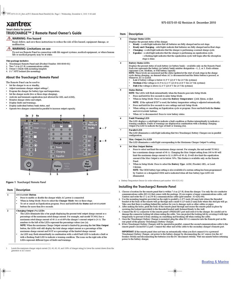
Xantrex
Xantrex TrueCharge 2 owner's guide

Migatronic
Migatronic PI 350 PLASMA manual
Honeywell
Honeywell Notifier ID50 installation, commissioning & configuration manual

GRASS VALLEY
GRASS VALLEY Kaleido-RCP2 Installation and operation manual

Bestherm
Bestherm Selene HE10EBA instruction manual
