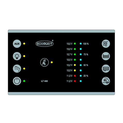
Schaudt LT 45 Series User manual

Date: 12.07.2018
ESchaudtGmbH, Elektrotechnik und Apparatebau, Planckstraße 8, 88677 Markdorf, Germany, Tel. +49 7544 9577-0,Fax +49 7544 9577-29,www.schaudt--gmbh.de
9310330 MA /EN
Installation Instructions
Operator and control panel Model LT 45X
AIways follow the corresponding operating instruction manual.
Table of contents
1Safetyinformation ...................................... 2
1.1 Meaningofsafetysymbols............................... 2
1.2 Generalsafetyinformation............................... 2
2 Introduction............................................ 3
3 Mechanicalinstallation................................... 3
4 Electricalconnection .................................... 4
4.2 Sensors ............................................... 5
4.3 ElectroblockEBL ... /caravan powersupplyCSV ... . ........ 5
5 Initialuse.............................................. 5
5.1 Checkspriortoinitialuse ................................ 5
5.2 Switching on and o the 12V supplyfor the leisure area ...... 5
5.3 Shuttingdown.......................................... 6
6 Storage,packagingandtransportation..................... 6

Installation Instructions Operator and control panel LT 45X
2Date: 12.07.2018 9310330 MA /EN
1Safetyinformation
1.1 Meaning of safety symbols
YDANGER!
Failure to comply with this sign may result in danger to life or physical con-
dition.
YWARNING!
Failure to comply with this sign may result in injury.
YATTENTION!
Failure to comply with the sign may result in damage to equipment or other
connected consumers.
1.2 General safety instructions
YDANGER!
230V parts carrying mains voltage.
Risk of fatal injury due to electric shock or re:
FThe motorhomeor caravanʼs electrical system must comply with DIN,
VDE and ISO regulations.
FConnect devices rated at 230V to the 230V supply in line with national
installation regulations.
FDo not try to modify the device.
FOnly carry out electrical work once the 230V supply has been discon-
nected.
FNever try to start the device using adefective mains cable or a faulty
connection.
FNever undertake maintenance on the device when it is live.
FEnsure proper electrical connections are made.
FEnsure correct electrical fuses are used.
YWARNING!
Hot components
Burns:
FBlown fuses may only be changed after the power to the system has
been disconnected
FBlown fuses may only be replaced once the cause of the fault is
known and has been rectied
FThe back of the device can get hot during operation. Do not touch it.
On the PCB of the device are components that can be destroyed by electro-
static discharge (ESD). Do not touch the componentson the PCB.

Installation Instructions Operator and control panel LT 45X
3
Date: 12.07.2018
9310330 MA /EN
2Introduction
These installation instructions are aimed at trained personnel.
They contain important information on the connection and safe operation of
the device. The safety informationprovided must be observed.
3Mechanicalinstallation
96**
(8*)
120**
48**
87*
43.5*
30**
(180)
(112)
171*4.5*
Corner
cutout
possible
Material thickness near
holes 9...12mm
10 (4x)*
222.422.4
9...12
Plug connectors Attachment clip
Fig. 1DimensiondiagramforLT 45X control and switch panel (dimensions in mm)
*Dimensions for furniture cut-out, installation depth 10 mm, plug-inconnector 30 mm
** Dimensions for centring of the 4 holes of the attachment clips
The device is intended for installation into the front of a piece of furniture.

Installation Instructions Operator and control panel LT 45X
4Date: 12.07.2018 9310330 MA /EN
"Install in a dry, suciently ventilated location.
FThe ambient temperature may not exceed +50 Cduring operation.
"Maintain aminimumclearance to the surrounding xtures and ttings:
FThe installation depth is 10 mm, near the 3 plug connectors 30 mm
Attach the LT 45X control panel:
"Make afurniture cutout as in Fig. 1.
"Insert the plug connector (see Section 4).
"Put on the panel, ensuring that the four attachment clips engage into the
four holes.
"Push the panel into the opening by the same amount until the front
plate is seated fully.
If an LT 45X control panel needs to be removed, rst carry out the steps
described in ”Preparation for the connection” (Section 4.1). Only then unplug
the electrical connections.
4Electricalconnection
Connect the rear of the LT 45X control and switch panel in the following se-
quence (please also refer to the block diagram and the rear view in the in-
struction manual):
1. All connectors to sensors/probes
2. Connection to an electroblock
Disconnect in the reverse order.
Block diagram/wiringdiagram
YThe block diagram and connection diagram are appended to the opera-
ting instructions for the LT 45X control panel.
4.1 Preparations for the connection
"Turn o the engine of the motorhome or unhitch the caravan and remove
the tow bar connector on the vehicle.
"Remove the CEE connectoron the vehicle or IEC connectoron the EBL
... or CSV ... power supply.
"Disconnect the solar module fromthe solar charge regulator (if available).
"Disconnect the terminals of the leisure area battery.
"Disconnect the terminals of the starter battery.
Environment
Minimum clearance
Fitting
Removal
Connection sequence
Disconnection

Installation Instructions Operator and control panel LT 45X
5
Date: 12.07.2018
9310330 MA /EN
4.2 Sensors
"Connect the tank sensors for two dierent tanks:
F5-pinconnector: Waste water tank
F6-pinconnector: Water tank
4.3 EBL... electroblock /CSV... caravan power supply
"Plug the ready-made cable (13-pin)into the LT 45X control panel.
"Plug the other end of the ready-made cable into the power supply unit
(EBL ... or CSV ...):
YTo identify the plug connector and for information on the pin plug-inas-
signment, refer to the operating instructions for the associated power
supply(EBL ... /CSV ...)
5Initialuse
5.1 Checks prior to initial use
"Ensure the leisure area battery is connected (and the starter battery as
required).
"Ensure that an electroblock or caravan power supply is connected (also
refer to the instruction manual and installation instructions for that elec-
troblock or power supply).
"Disable shutdown on the relevant power supply unit; to do this,
"enable the battery cut-oswitch of the relevant power supply
or
"attach the battery terminals
YAlso refer to the operating manual for the relevant power supply (EBL ... ,
CSV ...)
"Ensure that the accessory for measuring the ll level of the water tank is
connected and operational.
5.2 Switching on and o the 12V supply for the leisure area
"Connect the input to the mains supply of the vehicle to the 230V mains
supply.
Mains indicator LED lights up. The leisure area battery is being charged. For
details on the charge functions, refer to the operating instructions for the re-
levant power supply (EBL ... /CSV ...).
The 12V supply of the vehicle is switched on from the relevant button. The
refrigerator controller is an exception. It also works when the 12V power
supply is switched o --refer to the operating instructions for the relevant
power supply(EBL ... /CSV ...).
Prior to use
230Vmainsoperation

Installation Instructions Operator and control panel LT 45X
6Date: 12.07.2018 9310330 MA /EN
"Touch the sensor for the main 12V ON/OFF switch
FThe green indicator LED lights up.
FThe 12V leisure area supply is switched on.
5.3 Eecting ashutdown
YATTENTION!
Once the production of the vehicle is complete, the system MUST be
shut down.
"12V supply must be switched o.
"Disconnect the leisure area battery from the 12V on-boardsupply; to do
this:
"Disable the battery cut-oswitch of the relevant power supply
or
"Disconnect the battery terminals (depending on power supply)
YAlso refer to the operating manual for the relevant power supply (EBL ... /
CSV ...)
6Storage,packaging and transportation
Only transport and store the LT 45X control panel if the packing is suitable
and ambient conditions are dry.
No part of this manual may be reproduced, translated or copied without ex-
press written permission.
E

Datum: 12.07.2018
ESchaudtGmbH, Elektrotechnik und Apparatebau, Planckstraße 8, 88677 Markdorf, Germany, Tel. +49 7544 9577-0,Fax +49 7544 9577-29,www.schaudt--gmbh.de
9310330 MA /DE
Montageanleitung
Bedien-und Kontrollpanel Serie LT 45X
Immer zugehörige Bedienungsanleitung beachten.
Inhaltsverzeichnis
1Sicherheitshinweise..................................... 2
1.1 BedeutungderSicherheitshinweise ....................... 2
1.2 AllgemeineSicherheitshinweise........................... 2
2 Einleitung.............................................. 3
3 MechanischerEinbau ................................... 3
4 ElektrischerAnschluss .................................. 4
4.2 Sensoren.............................................. 5
4.3 ElektroblockEBL ... bzw.Caravan-StromversorgungCSV ... .. 5
5 Erstinbetriebnahme ..................................... 5
5.1 PrüfungenvorErstinbetriebnahme ........................ 5
5.2 Ein-und Ausschaltender 12 VVersorgungWohnraum....... 5
5.3 Stilllegungherbeiführen.................................. 6
6Lagerung-Verpackung-Transport........................ 6

Montageanleitung Bedien-und Kontrollpanel LT 45X
2Datum: 12.07.2018 9310330 MA /DE
1Sicherheitshinweise
1.1 Bedeutung der Sicherheitshinweise
YGEFAHR!
Die Nichtbeachtung dieses Zeichens kann zur Gefährdung von Leib und
Leben führen.
YWARNUNG!
Die Nichtbeachtung dieses Zeichens kann zu Verletzungen von Personen
führen.
YACHTUNG!
Die Nichtbeachtungdieses Zeichens kann zu Schäden am Gerät oder an
angeschlossenen Verbrauchern führen.
1.2 Allgemeine Sicherheitshinweise
YGEFAHR!
230 VNetzspannung führende Teile.
Lebensgefahr durch elektrischen Schlag oder Brand:
FElektrische Anlage des Reisemobils oder Caravans muss geltenden
DIN-, VDE-und ISO-Richtlinien entsprechen.
FGeräte mit 230 VNetzanschluss entsprechend den nationalen Instal-
lationsvorschriften an das 230 VNetz anschließen.
FKeine Veränderungen am Gerät vornehmen.
FAnschlussarbeiten nur ausführen, wenn keine Verbindung zu einer
230 VVersorgung besteht.
FGerät nicht mit defektem Netzkabel oder fehlerhaftem Anschluss in
Betrieb nehmen.
FKeine Wartungsarbeiten am Gerät durchführen,wenn Spannung an-
liegt.
FElektrische Anschlüsse sachgemäß durchführen.
FRichtige elektrische Absicherung sicherstellen.
YWARNUNG!
Heiße Bauteile!
Verbrennungen:
FDefekte Sicherungen nur auswechseln, wenn das System stromlos
ist.
FDefekte Sicherungen nur auswechseln, wenn die Fehlerursache be-
kannt und beseitigt ist.
FRückseite von Geräten kann im Betrieb heiß werden. Nicht berühren.
Auf der Leiterplatte des Gerätes benden sich Bauteile, die durch elektrosta-
tische Entladung (ESD) zerstört werden können. Die Bauteile auf der Leiter-
platte dürfen nicht berührt werden.

Montageanleitung Bedien-und Kontrollpanel LT 45X
3
Datum: 12.07.2018
9310330 MA /DE
2Einleitung
Diese Montageanleitung wendet sich an ausgebildetes Fachpersonal.
Sie enthält wichtige Hinweise zum Anschließen und zum sicheren Betrieb
des Gerätes. Die angegebenen Sicherheitshinweise sind unbedingtanzu-
wenden.
3MechanischerEinbau
96**
(8*)
120**
48**
87*
43.5*
30**
(180)
(112)
171*4.5*
Eckenaus
fräsung
möglich
Materialstärke im Bereich der
Bohrungen 9...12mm
10 (4x)*
222.422.4
9...12
Steckverbinder
Befestigungs--Clip
Bild 1 Maßbild Bedien-und Kontrollpanel LT 45X (Abmessungen in mm)
*Maße für Möbelausschnitt, Einbautiefe 10mm,Steckverbinder 30 mm
** Abmessungen Zentrierung der 4 Bohrungen der Befestigungsclips
Das Gerät ist für den Einbau in eine Möbelfrontvorgesehen.

Montageanleitung Bedien-und Kontrollpanel LT 45X
4Datum: 12.07.2018 9310330 MA /DE
"Trockenen und ausreichend belüfteten Einbauort wählen.
FWährend des Betriebs darf die Umgebungstemperatur +50Cnicht
überschreiten.
"Mindestabstände zu den umgebenden Einrichtungsgegenständen sicher-
stellen:
FDie Einbautiefe beträgt 10 mm, im Bereich der 3 Steckverbinder
30 mm
Bedien-und Kontrollpanel LT 45X befestigen:
"Möbelausschnitt gemäß Bild 1 herstellen.
"Steckverbinder einstecken (s. Kap. 4).
"Panel aufsetzen --dabeidarauf achten, dass die vier Befestigungsclips in
die vier Bohrungen greifen.
"Panel gleichmäßig in die Önung schieben, bis die Frontplatte vollstän-
dig auiegt.
Wenn ein Bedien-und Kontrollpanel LT 45X ausgebaut werden muss, zu-
nächst die in Kap. 4.1 ”Vorbereitungfür das Anschließen” genannten Ar-
beitsschritte durchführen.Erst danach die elektrischen Anschlüsse trennen.
4ElektrischerAnschluss
Den Anschluss auf der Rückseite des Bedien-und Kontrollpanels LT 45X in
folgender Reihenfolge durchführen(siehe hierzu auch das Blockschaltbild
und die Rückansicht in der Bedienungsanleitung):
1. Alle Anschlüsse zu Sensoren bzw. Sonden
2. Anschluss an den Elektroblock
Das Abklemmen in sinngemäß umgekehrter Reihenfolge durchführen.
Blockschaltbild/Anschlussplan
YBlockschaltbild/Anschlussplan sind im Anhang der Bedienungsanleitung
des Bedien-und Kontrollpanels LT 45X zu nden.
4.1 Vorbereitungen für das Anschließen
"Motor des Reisemobils abstellen bzw. Caravan abkuppeln und AHK-
Stecker am Fahrzeug abziehen.
"CEE-Netzstecker am Fahrzeug oder Kaltgerätestecker an der Stromver-
sorgungEBL ... bzw.CSV ... abziehen.
"Solarmodul am Solar-Laderegler abziehen (wenn vorhanden).
"Batteriepole der Wohnraumbatterie abnehmen.
"Batteriepole der Starterbatterie abnehmen.
Umgebung
Mindestabstand
Befestigung
Ausbau
Anschluss-Reihenfolge
Abklemmen

Montageanleitung Bedien-und Kontrollpanel LT 45X
5
Datum: 12.07.2018
9310330 MA /DE
4.2 Sensoren
"Tanksensoren für zwei verschiedene Tanks anschließen:
FStecker 5polig:Abwassertank
FStecker 6polig:Wassertank
4.3 Elektroblock EBL ... bzw. Caravan-StromversorgungCSV ...
"Das vorkonfektionierte Kabel (13 polig) an Bedien-und Kontrollpanel
LT 45X einstecken.
"Das andere Ende des vorkonfektioniertenKabels am Stromversorgungs-
gerät (EBL ... oderCSV ...) einstecken:
YZur Identikation des Anschlusssteckers und für Informationen zu Pinbe-
legung des Steckers siehe Bedienungsanleitung der zugehörigenStrom-
versorgung(EBL ... /CSV ...)
5Erstinbetriebnahme
5.1 Prüfungen vor Erstinbetriebnahme
"Sicherstellen, dass die Wohnraumbatterie (und ggf. die Starterbatterie)
angeschlossen ist.
"Sicherstellen, dass ein Elektroblock bzw. die Caravan-Stromversorgung
angeschlossen ist (siehe auch Bedienungsanleitung und Montageanlei-
tung des Elektroblocks/der Stromversorgung).
"Stilllegung am entsprechenden Stromversorgungsgerät deaktivieren;
dazu:
"Batterietrennschalter der zugehörigen Stromversorgung einschal-
ten
bzw. (je nach Stromversorgung)
"Batteriepole aufsetzen
YSiehe hierzu Bedienungsanleitung der zugehörigen Stromversorgung
(EBL ... ,CSV ...)
"Sicherstellen, dass das Zubehör fürdie Füllstandsmessung des Wasser-
tanks angeschlossen und betriebsbereit ist.
5.2 Ein-und Ausschalten der 12 VVersorgungWohnraum
"Eingang zur Netzversorgung des Fahrzeugs an die 230 VNetzversor-
gung anschließen.
LED Netzkontrolle leuchtet. Die Wohnraumbatterie wird geladen; für Details
über die Ladefunktionen siehe Bedienungsanleitung der zugehörigen Strom-
versorgung(EBL ... /CSV ...).
Die 12 V Versorgung des Fahrzeugs wird über den entsprechenden Taster
eingeschaltet. Ausgenommen ist die Kühlschrank-Steuerung. Sie ist auch
bei ausgeschalteter 12 VStromversorgung betriebsbereit, siehe Bedie-
nungsanleitungder zugehörigenStromversorgung (EBL ... /CSV ...).
Vor der Inbetriebnahme
230 VNetzbetrieb

Montageanleitung Bedien-und Kontrollpanel LT 45X
6Datum: 12.07.2018 9310330 MA /DE
"Das Sensor-TastfeldHauptschalter 12 VEIN /AUS berühren.
FDie grüne Kontroll-LED leuchtet.
FDie 12 V Versorgung des Wohnraums ist eingeschaltet.
5.3 Stilllegung herbeiführen
YACHTUNG!
Nachdem die Produktion des Fahrzeugs abgeschlossen ist, MUSS das
System stillgelegt werden.
"12 VVersorgung ausschalten.
"Die Wohnraumbatterie vom 12-V-Bordnetztrennen; dazu:
"Batterietrennschalter der zugehörigen Stromversorgung ausschal-
ten
bzw. (je nach Stromversorgung)
"Batteriepole abnehmen
YSiehe hierzu Bedienungsanleitung der zugehörigen Stromversorgung
(EBL ... /CSV ...)
6Lagerung-Verpackung -Transport
Das Bedien-und Kontrollpanel LT 45X nur in geeigneter Verpackung und
trockener Umgebung transportieren und lagern.
Nachdruck, Übersetzung und Vervielfältigung dieser Dokumentation, auch
auszugsweise, ist ohne schriftliche Genehmigung nicht gestattet.
E
Other manuals for LT 45 Series
1
This manual suits for next models
1
Table of contents
Languages:
Other Schaudt Control Panel manuals
Popular Control Panel manuals by other brands

Procon
Procon 8404 instruction manual

Crow
Crow Power Wave - 8 installation manual
G-Force
G-Force UNDER CONTROL CP-34 PILOT user manual
Extron electronics
Extron electronics RCP 101 D Setup guide
Spraying Systems
Spraying Systems AutoJet 1000+ quick start guide

Paradox
Paradox Digiplex DGP-848 Reference and installation manual
