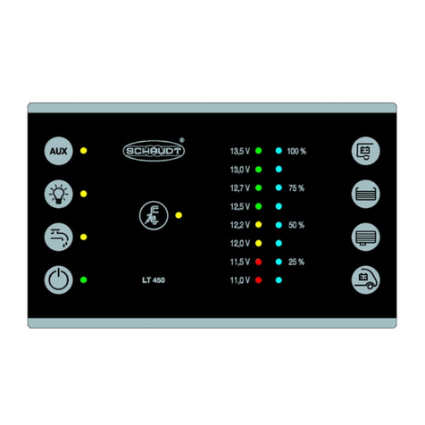
Schaudt LT 4 Series User manual

CamperEnCaravanOnderdelen.nl
Date: 13.09.2013
ESchaudt GmbH, Elektrotechnik und Apparatebau, Planckstraße 8, 88677 Markdorf, Germany, Tel. +49 7544 9577-0, Fax +49 7544 9577-29, www.schaudt--gmbh.de
831.414 BA / EN
Instruction Manual
LT 4XX Family of Switch Panels
Table of contents
1 Safety Information 2......................................
1.1 Meaning of safety symbols 2...............................
1.2 General safety information 2...............................
2 Introduction 2............................................
3 Operation 5..............................................
3.1 Design 5................................................
3.2 Operating controls 5......................................
3.3 Displays 6...............................................
3.4 Starting up 7.............................................
3.5 Switching on 7...........................................
3.6 Checking readings 7......................................
3.7 Troubleshooting and remedies 10............................
3.8 Switching off 11...........................................
3.9 Closing down the system 11................................
4 Maintenance 11...........................................
5 Application and function 12.................................
Appendix 13..............................................

CamperEnCaravanOnderdelen.nl
Instruction Manual for the LT 4XX Family of Switch Panels
2
Date: 13.09.2013 831.414 BA / EN
1 Safety Information
1.1 Meaning of safety symbols
Y
DANGER!
Failure to heed this warning may result in death or serious injury.
Y
WARNING!
Failure to heed this warning may result in personal injuries.
Y
ATTENTION!
Failure to heed this warning may result in damage to the device or connec-
ted consumers.
1.2 General safety information
The device is state-of-the-art and complies with approved safety regulations.
Nonetheless, personal injuries or damage to the device may occur if the sa-
fety instructions contained herein are not followed.
Ensure that the device is in perfect working order before use.
Any technical faults which may impact personal safety or the safety of the
device must be rectified immediately by qualified personnel.
Y
WARNING!
Hot components!
Burns:
F
Only change blown fuses when the device is completely de-energised.
F
Only replace blown fuses once the cause of the fault has been identi-
fied and rectified.
F
Never bypass or repair fuses.
F
Only use original fuses rated as specified on the device.
F
Device parts can become hot during operation. Do not touch.
F
Never store heat sensitive objects close to the device (e.g. tempera-
ture sensitive clothes if the device has been installed in a wardrobe).

CamperEnCaravanOnderdelen.nl
Instruction Manual for the LT 4XX Family of Switch Panels
3
Date: 13.09.2013
831.414 BA / EN
2 Introduction
This instruction manual contains important information on the safe operation
of equipment supplied by Schaudt. Make sure you read and follow the safety
instructions provided.
The instruction manual should be kept in the vehicle at all times. Ensure that
other users are made aware of the safety regulations.
The switch panels differ in their configurations and the depiction of symbols.
Y
This document covers all LT 4XX switch panels. The following table pro-
vides an overview of the configuration features.
Model Examples of front panels
12V In/Out
Display of 230V
connected
Voltage display of
living area battery
Voltage display of
starter battery
Total
discharge
a
i
g
Fill level display of
water tank
Fill level display of
waste water tank
Switch for water
pump
Switch for
lighting
Switch for reserve
output (AUX)
LT 400
LT 400 A XXXXXXXXXX
LT 402 XXXXXXX X
LT 410 XXXXXXX
LT 411 XXX XX
Configuration

CamperEnCaravanOnderdelen.nl
Instruction Manual for the LT 4XX Family of Switch Panels
4
Date: 13.09.2013 831.414 BA / EN
Model
Switch for reserve
output (AUX)
Switch for
lighting
Switch for water
pump
Fill level display of
waste water tank
Fill level display of
water tank
Total
discharge
warning
Voltage display of
starter battery
Voltage display of
living area battery
Display of 230V
connected
12V In/Out
Examples of front panels
LT 412 XXX XX
LT 413 X X X X X X
LT 413-2 XXX XXXX
LT 419 X X X X X X
LT 420 XXXXXXXX
LT 421 XXXXXXXX

CamperEnCaravanOnderdelen.nl
Instruction Manual for the LT 4XX Family of Switch Panels
5
Date: 13.09.2013
831.414 BA / EN
3 Operation
3.1 Design
The switch panel is intended for installation in a cabinet or wall.
1
2
Fig. 1 Layout of LT 4XX switch panel
1 Displays
2 Control panels
Y
Symbols and inscription vary depending on vehicle manufacturer.
3.2 Operating controls
The LT 4XX switch panels have the following controls:
Button: Main switch
Button to switch on and off the 12V supply of the motorhome.
Button: Button for checking battery voltages
(for LT 411, LT 412 only for living area battery)
Button: Button for checking the tank fill level
(for LT 411, LT 412, only for one water tank)
*Only LT 400 and LT 420, 421:
Switch: Pump supply voltage

CamperEnCaravanOnderdelen.nl
Instruction Manual for the LT 4XX Family of Switch Panels
6
Date: 13.09.2013 831.414 BA / EN
**Only LT 400, 402:
Switch: Supply voltage for additional device
**Only LT 400:
Switch: Supply voltage for lighting
3.3 Displays
The LT 4XX switch panels have the following displays:
Display of the battery charge in eight increments with voltage information
and total discharge warning
Display of the tank fill level in five increments: empty (no LED on), 25% (2
LEDs on), 50% (4 LEDs on), 75% (6 LEDs on), full (all LEDs on)
LED mains indicator (yellow)
The yellow LED is on when mains voltage is present at the input of the EBL
electrobloc (see also Section ”Starting up” in EBL.... electrobloc instruction
manual)
Indicator LED (green)
Indicates the system is switched on.
*Only LT 400 and LT 420, 421:
Indicator LED (green):
Indicates the pump supply voltage is switched on.
**Only LT 400, 402:
Indicator LED (green):
Indicates the additional device supply voltage is switched on.
**Only LT 400:
Indicator LED (green):
Indicates the lighting supply voltage is switched on.

CamperEnCaravanOnderdelen.nl
Instruction Manual for the LT 4XX Family of Switch Panels
7
Date: 13.09.2013
831.414 BA / EN
3.4 Starting up
"
Switch on LT 4XX switch panel (see Section 3.5).
"
Connect the plug for mains operation to the 230V power supply.
Mains indicator LED lights up. The living area battery is being charged (also
the starter battery if required; please refer to the instruction manual of the
appropriate electrobloc for details on the charging functions).
3.5 Switching on
The 12V supply of the living area is switched on using the relevant button.
Exceptions:
F
AES refrigerator controller
and, if available, the following outputs:
F
Compressor refrigerator
F
Frost protection valve heater system
F
Floor light
F
Spare 1
These consumers are also operable when the 12V power supply is switched
off (as soon as a battery is connected or mains voltage is applied).
"
Briefly press the left-hand button upwards.
The green indicator LED lights up.
The 12V supply to the living area is now switched on.
3.6 Checking readings
3.6.1 Battery charge
"
Briefly press the button next to the left-hand scale upwards.
The charge of the starter battery is displayed (not present for LT411, LT412,
LT 413):
F
Green LEDs: Battery charged sufficiently
F
Yellow LEDs: Battery partially discharged (below 12.4V)
F
Red LEDs: Battery flat (below 11.6V)
"
Briefly press the button next to the left-hand scale downwards.
The charge of the living area battery is displayed.
F
Green LEDs: Battery charged sufficiently
F
Yellow LEDs: Battery partially discharged (below 12.4V)
F
Red LEDs: Battery flat (below 11.6V)
230V mains operation

CamperEnCaravanOnderdelen.nl
Instruction Manual for the LT 4XX Family of Switch Panels
8
Date: 13.09.2013 831.414 BA / EN
Y
Note on LT 411, LT 412 LT 413:
The display is only for a living area battery for the LT 411, LT412, LT 413:
"
Briefly press the button next to the right-hand scale upwards ordown-
wards.
The following table shows the correct interpretation of the voltage of the li-
ving area battery displayed on the scale.
These values apply to actual operation, not off-load voltage.
B
a
t
t
e
r
y
v
o
l
t
a
g
Battery operation Mobile operation Power operation
B
atteryvo
l
tag
eVehicle stationary,
no 230V connection Vehicle moving Vehicle stationary,
230V connection
less than
11.0V
Risk of total
If consumers are
switched off:
battery flat
the alternator is not
charging the battery the electrobloc is
not charging the
battery
R
i
s
k
o
f
t
o
t
a
l
discharge if many consumers
are switched on:
possible battery
overload
12V power supply
overloaded 12V power supply
overloaded
11,5V to 13.0V normal range the alternator is not
charging the
battery
1)
the electrobloc is
not charging the
battery
1)
12V power supply
overloaded
1)
12V power supply
overloaded
1)
13,5V and over occurs only briefly
after charging Battery being
charged Battery being
charged
1)
If the voltage does not exceed this range for several hours.
Y
ATTENTION!
Total discharge.
Damage to the living area battery:
F
Prevent low battery charge (indicated by low voltage).
F
Switch off some consumers in the event of an overloaded power sup-
ply.
F
Prior to taking the motorhome out of service, ensure no more inactive
consumers are connected.
Measuring the off-load voltage is a simple and effective method of checking
the condition of the battery. Off-load voltage is the voltage of the charged
battery in a passive state, with no current being supplied or drawn.
Take the measurement several hours after the last charging. In the mean-
time, no significant load should have been placed on the battery, meaning no
current should have been drawn from it. There is a risk of total discharge if
the off-load voltage of the battery is 12.0V or less.
The following table shows the correct interpretation of the off-load voltage
displayed. The values specified are guidelines for gel batteries.
Values for off-load voltage Charge state of the battery
12.0V or less discharge or total discharge
12.2V approx. 25%
12.5V approx. 50%
More than 12.7V full
Off-load voltage

CamperEnCaravanOnderdelen.nl
Instruction Manual for the LT 4XX Family of Switch Panels
9
Date: 13.09.2013
831.414 BA / EN
3.6.2 Tank fill levels
Y
ATTENTION!
Measuring too long.
Damage to rod tank probes or tank sensors:
F
Briefly press keys to check tank fill levels.
"
Briefly press the button next to the right-hand scale upwards.
The water tank level is displayed.
F
All LEDs light up: full
F
Six LEDs light up: 3/4 full
F
Four LEDs light up: 1/2 full
F
Two LEDs light up: 1/4 full
F
No LEDs light up: Tank empty
"
Briefly press the button next to the right-hand scale downwards.
The waste water tank level is displayed.
F
All LEDs light up: full
F
Six LEDs light up: 3/4 full
F
Four LEDs light up: 1/2 full
F
Two LEDs light up: 1/4 full
F
No LEDs light up: Tank empty
Y
Note on LT 411, LT 412, LT 413:
The display is only for a water tank on the LT 411, LT 412, LT 413:
"
Briefly press the button next to the right-hand scale upwards ordown-
wards.
3.6.3 Switching voltage supplies on and off
3.6.3.1 Water pump
*Only LT 400 and LT 420, 421:
"
Press the switch with the pump symbol upwards.
The supply voltage for the water pump is enabled:
F
Green LED lights up.
F
The pump may switch on briefly (e.g. in a pressure system).
3.6.3.2 Lighting
*Only LT 400:
"
Press the switch with the lighting symbol upwards.
The supply voltage for the lighting is switched on:
F
Green LED lights up.
F
Lighting can be switched on.

CamperEnCaravanOnderdelen.nl
Instruction Manual for the LT 4XX Family of Switch Panels
10
Date: 13.09.2013 831.414 BA / EN
3.6.3.3 Additional devices
*Only LT 400, 402:
"
Press the switch with the symbol for additional device(s) (Aux, ) up-
wards.
The supply voltage for the additional device(s) is switched on:
F
Green LED lights up.
F
Connected device(s) can be switched on.
3.7 Troubleshooting and remedies
3.7.1 Alarms
Y
ATTENTION!
Total discharge.
Damage to the living area battery:
F
Prevent low battery charge (indicated by low voltage).
F
Check the voltage regularly (see Section 3.6.1).
Y
Carry out checks in the mornings before 12V consumers are switched
on.
Alarm Possible cause Remedy
Risk of draining the living
area battery. Switch off all 12V
consumers.
y
Voltage of the living area
battery has fallen below
11.0V.
Recharge the battery:
-- Start engine
or
-- connect to 230V power
supply
3.7.2 Faults
The majority of power supply system faults are caused by blown fuses (refer
to the instruction manual for the relevant electrobloc for information on vol-
tage distribution and fusing).
Please contact our customer service department if you can not rectify the
fault using the following table.
If this is not possible, e.g. if you are abroad, the switch panel can be repai-
red at a specialist workshop. Please note that the warranty will become void
if incorrect repair work is carried out. Schaudt GmbH shall not accept liability
for any damages resulting from such repairs.
Fault Possible cause Remedy
12V supply does not
function (or some areas
t
d
)
12V main switch is
switched off. 12V main switch must be
switched on.
(
are not powered). Fuse blown. See EBL ... electrobloc
instruction manual. .
Flat vehicle fuses

CamperEnCaravanOnderdelen.nl
Instruction Manual for the LT 4XX Family of Switch Panels
11
Date: 13.09.2013
831.414 BA / EN
Fault RemedyPossible cause
12V indicator LED (green)
does not light up. 12V main switch is
switched off. 12V main switch must be
switched on.
g
p
Living area battery not
charged Recharge the living area
battery.
Fuse blown. See EBL ... electrobloc
instruction manual. .
Living area battery is flat. Living area battery has
been discharged Recharge the living area
battery immediately.
The living area battery will
be damaged beyond repair
if it remains totally
discharged for a lengthy
period.
Thebatterycanbe
discharged by inactive
consumers, such as the
frost protection valve in
the combined heating
system.
Fully recharge the living
area battery before taking
the motorhome out of
service for a lengthy
period.
The ”Check mains” LED
(yellow) does not light up
even though the 230V
i
l
i
No power coming from the
mains supply. Check the mains
connection (e.g. camping
site).
g
mains supply is
connected. The power cut-out in front
of the Electrobloc has
tripped or is switched off.
Reset the power cut-out.
3.8 Switching off
"
Briefly press down the left-hand button.
The green indicator LED goes out.
The 12V supply to the living area is now switched off.
Exceptions:
F
Compressor/AES refrigerator control unit, possibly step
These consumers are still operable even when the 12V power supply is swit-
ched off.
3.9 Closing down the system
The system should be switched off if the vehicle is not being used for a leng-
thy period, such as during the winter.
"
Disconnect the living area battery from the 12V onboard supply (remove
battery poles).
"
More detailed information on closing down the system can be found in
the EBL ... electrobloc instruction manual.
4 Maintenance
The LT 4XX switch panels require no maintenance.
Clean the device with a soft, slightly damp cloth and mild detergent. Never
use spirit, thinners or similar substances. Do not allow fluid to penetrate the
inside of the switch panel.
Cleaning

CamperEnCaravanOnderdelen.nl
Instruction Manual for the LT 4XX Family of Switch Panels
12
Date: 13.09.2013 831.414 BA / EN
5 Application and function
The LT 400, LT 410, LT 420 and LT 421 switch panels are the central control
panels for the EBL ... Electrobloc supplying all 12V consumers in the electri-
cal system on board the motorhome. They are usually installed in an easily
accessible place high up near the door of the motorhome.
EBL ...
+--
+--
Electrobloc 230V AC
12V consumers
Living area battery
Starter battery Lighting
Pump
Heater
etc.
LT 4XX switch panel
CSV ...
Fig. 2 On-board power supply system
An Electrobloc EBL ... must be connected for operation. This provides the
12V supply to the devices in the motorhome and charges the living area and
vehicle batteries
The following connection options are possible:
F
Electrobloc EBL ...
F
Sensors and/or probe for water tank
F
Sensors or probe for waste water tank
The LT 4XX switch panel has the task of switching on and off the 12V supply
for the living area and of displaying the different readings.
The following data can be displayed:
F
Voltage of living area battery
F
Voltage of vehicle battery (starter battery)
F
Fill level of water tank
F
Mains supply present
No part of this manual may be reproduced, translated or copied without ex-
press written permission.
System devices
Display functions
E

CamperEnCaravanOnderdelen.nl
Instruction Manual for the LT 4XX Family of Switch Panels
13
Date: 13.09.2013
831.414 BA / EN
Appendix
A EC Declaration of Conformity
Schaudt GmbH hereby confirms that the design of switch panels LT 4XX
complies with the following relevant regulations:
Directive on electromagnetic compatibility
2004/108/EC dated 15.12.2004
The original EC Declaration of Conformity is available for reference at any
time.
Schaudt GmbH, Elektrotechnik & Apparatebau
Planckstraße 8
88677 Markdorf
Germany
B Special fittings/accessories
2 x rod-type tank probe, 2 x seal,
2 x locking nut, 2 x probe cable (5 x 0.5)
Alternative:
10 x tank sensor, 2 x sensor cable 5 x 0.5
Mixed operation of tank probes and tank sensors is possible.
C Customer service
Schaudt GmbH, Elektrotechnik & Apparatebau
Planckstraße 8
D-88677 Markdorf
tel.: +49 7544 9577-16 e-mail: kundendienst@schaudt-gmbh.de
Office hours Mon to Thurs 08.00 -- 12.00, 13.00 -- 16.00
Fri 08.00 -- 12.00
Returning a defective device:
"
Fill in and enclose the fault report, see Appendix D.
"
Send it to the addressee (free of charge).
Manufacturer
Address
Rod-type tank probes
Tank sensors
Mixed operation
Customer service
address
Send in the device

CamperEnCaravanOnderdelen.nl
Instruction Manual for the LT 4XX Family of Switch Panels
14
Date: 13.09.2013 831.414 BA / EN
D Fault report
In the event of damage, please return the defective device together with the
completed fault report to the manufacturer.
Device type: _______________________
Article no.: _______________________
Vehicle: Manufacturer: _______________________
Model: _______________________
Own installation? Yes -No -
Upgrade? Yes -No -
There is the following defect:
(please select)
Other remarks:
no Battery-
charge during
mobile
operation
no Battery-
charge
during mains
operation
Tank Voltage
Permanent fault
Intermittent
fault/loose
contact
The following
electrical
consumers do
not work:
Malfunction of
switch panel

CamperEnCaravanOnderdelen.nl
Instruction Manual for the LT 4XX Family of Switch Panels
15
Date: 13.09.2013
831.414 BA / EN
E Block diagram/connection diagram
1
2
3
4
5
6
1
2
3
4
5
1
2
3
4
5
6
7
8
9
10
11
12
Circuit board
X1 X2
X3
X4
123
Fig. 3 Connection diagram of LT 4XX switch panels
X1 Lumberg MSFQ 6-way on water tank
1full
23/4
31/2
41/4
5 Base water tank
6n.c.
X2 Lumberg MSFQ 5-way on waste water tank (not for LT 411, LT 412)
1full
23/4
31/2
41/4
5 Base waste water tank
X3 Lumberg MSFQ 12-way on EBL ... Electrobloc
1n.c.
2 Negative living area battery sensor
3 + Lighting, only LT 400
4n.c.
5 12V indicator
6 230V indicator
7 + Additional device(s) (AUX), only LT 400, 402
8 + Starter battery, 12V
9 12V On
10 + Pump (only LT 400 and LT 420, 421)
11 + Sensor, living area battery
12 12V Off
X4 Solder pads
1GND
2 +12V permanent positive
3 +12V, connected via ”12V On/Off”

CamperEnCaravanOnderdelen.nl
Instruction Manual for the LT 4XX Family of Switch Panels
16
Date: 13.09.2013 831.414 BA / EN
(------)
Table of contents
Other Schaudt Control Panel manuals
Popular Control Panel manuals by other brands
TIS
TIS Venera Switch Installation and programming manual
Carlisle
Carlisle Ransburg DynaFlow 77376 Service manual
Exodraft
Exodraft EBC30 Installation and operation manual
Siterwell
Siterwell GS690 Installation and service manual
ELECTRONIC ASSEMBLY
ELECTRONIC ASSEMBLY EA KIT160-6 manual
CAME
CAME Z Series manual
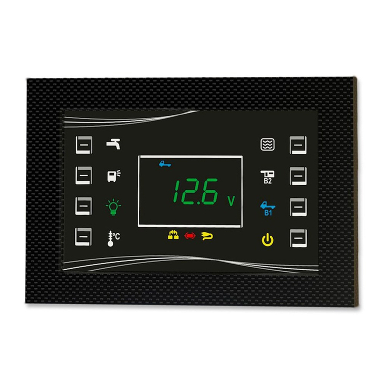
Nordelettronica
Nordelettronica NE274 instruction manual
Zeta Alarm Systems
Zeta Alarm Systems SMARTCONNECT SMART6 installation manual
FireClass
FireClass FC503 Programming manual

Context Plus
Context Plus CAST XFP Series user manual
Honeywell
Honeywell Gamewell GFANN-80 Product installation document
Honeywell
Honeywell Galaxy 16 user guide
