Schaudt LT 45 Series User manual

ESchaudt GmbH, Elektrotechnik und Apparatebau, Planckstraße 8, 88677 Markdorf, Germany, Tel. +49 7544 9577-0, Fax +49 7544 9577-29, www.schaudt--gmbh.de
9310330 BA / EN Date: 29.05.2020
Operating Instructions
Operator and control panel LT 45X
Table of contents
1 Introduction 2............................................
2 Application and function 5.................................
3 Operation 6..............................................
3.1 Layout 6................................................
3.2 Starting up 7.............................................
3.3 Switching on 7...........................................
3.4 Activating consumers 7....................................
3.5 Checking battery voltage 8.................................
3.6 Checking tank levels 9....................................
3.7 Troubleshooting and remedies 10............................
3.8 Switching off 11...........................................
3.9 Closing down the system 11................................
4 Maintenance 11...........................................
Appendix 12..............................................

Operating Instructions Operator and control panel LT 45X
2Date: 29.05.2020 9310330 BA / EN
1 Introduction
This instruction manual contains important information for the safe operation
of equipment supplied by Schaudt.
The operating instructions should always be kept in the vehicle.
YATTENTION!
Failure to comply with the sign may result in damage to equipment or other
connected loads.
LT 45X control panels differ as regards their configurations and the depiction
of symbols.
YThis documentation covers all LT 45X control panels. The following table
provides an overview of the configuration features.
Model Front panel
12 V ON/OFF
Mains indicator
Voltage display
Leisure area battery
Voltage display
Starter battery
Fill level display
Water tank
Fill level display
Waste water tank
Pump switch
Light switch
AUX switch
LT450 X X X X X X X X X
LT451 X X X X X X
LT452 X X X X X X X
Configuration

Operating Instructions Operator and control panel LT 45X
3
Date: 29.05.2020
9310330 BA / EN
Model
AUX switch
Light switch
Pump switch
Fill level display
Waste water tank
Fill level display
Water tank
Voltage display
Starter battery
Voltage display
Leisure area battery
Mains indicator
12 V ON/OFF
Front panel
LT452* X X X X X X X*
LT453 X X X X X X X

Operating Instructions Operator and control panel LT 45X
4Date: 29.05.2020 9310330 BA / EN
Model
AUX switch
Light switch
Pump switch
Fill level display
Waste water tank
Fill level display
Water tank
Voltage display
Starter battery
Voltage display
Leisure area battery
Mains indicator
12 V ON/OFF
Front panel
LT454 X X X X X
LT455 X X X X X X
* Symbol “Multimedia” instead of AUX

Operating Instructions Operator and control panel LT 45X
5
Date: 29.05.2020
9310330 BA / EN
2 Application and function
The LT 45X control panel is the central device for the EBL ... power supply,
which powers all 12 V consumers in the vehicle’s on-board electrical system.
It is usually installed in an easily accessible place high up near the door of
the vehicle.
+--
+--
LT 45X
control panel
Power supply
EBL ...
Starter battery
Lighting
Pump
Heater
etc.
230 V AC
12 V consumersLeisure area battery
Water tank
Waste water tank
Fig. 1 On-board power supply system
The main layout of the on-board vehicle electrical system is shown in Fig. 1.
The functions of the LT 45X control panel are to switch on and off the 12V
supply to the vehicle, and to display the battery voltage, tank levels and con-
nection to the mains supply (230 V).
An EBL ... power supply must be connected for operation. This provides the
12V supply to the devices in the vehicle and charges the battery.
The following connection options are available:
FEBL ... power supply
FWater tank probe
FWaste water tank probe or sensors
Purpose
Function
System devices

Operating Instructions Operator and control panel LT 45X
6Date: 29.05.2020 9310330 BA / EN
3 Operation
3.1 Layout
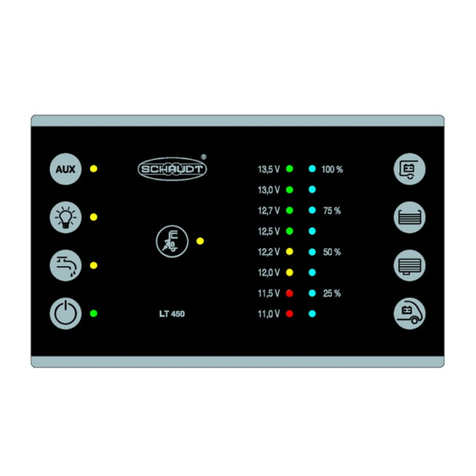
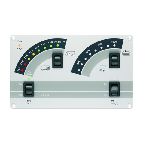
The LT 45X control panel is intended for installation in a cabinet or wall.
2
1
2.12.2 2.6 2.7
1.1
1.5
1.7
1.6
1.2
1.3
1.4
1.8
2.32.42.5
Fig. 2 Layout of LT 45X control panel
1Touch sensor 2Displays
-- -- 2.1
LED mains indicator (yellow):
The LED lights up when mains voltage is pre-
sent at the input of the vehicle mains supply
(also refer to the instruction manual for the
relevant EBL ... , Section ”Starting up”).
1.1
Main switch, 12 V ON/OFF:
For switching on and off the 12V supply of the
vehicle
2.2 Indicator LED (green):
Display: 12 V vehicle supply ON
1.2
Pump switch:
For switching on and off the 12V supply for
the water pump
2.3 Indicator LED (yellow):
Display: Pump supply ON
1.3
Light power:
For switching on and off the 12V supply for
the leisure area lighting
2.4 Indicator LED (yellow):
Display: Power for lighting ON
1.4
AUX supply:
For switching on and off the 12 V AUX supply
(e.g. for radio and TV)
2.5 Indicator LED (yellow):
Display: AUX power ON
1.5 Check of leisure area battery voltage
2
6
8 LEDs (2 red -- 2 yellow -- 4 green):
D
i
s
p
l
a
y
o
f
b
a
t
t
e
r
y
v
o
l
t
a
g
e
i
n
8
i
n
c
r
e
m
e
n
t
s
a
n
d
1.6 Check of starter battery voltage
2
.
6
D
i
sp
l
ay o
f
b
a
t
t
ery vo
l
t
age
i
n
8
i
ncremen
t
san
d
warning of total discharge.
1.7 Check of water tank level
2
7
8 LEDs (blue):
D
i
s
p
l
a
y
o
f
w
a
t
e
r
a
n
d
w
a
s
t
e
w
a
t
e
r
t
a
n
k
l
e
v
e
l
s
1.8 Check of waste water tank level
2
.
7
D
i
sp
l
ay o
f
wa
t
er an
d
was
t
ewa
t
er
t
an
k
l
eve
l
s
(four increments).

Operating Instructions Operator and control panel LT 45X
7
Date: 29.05.2020
9310330 BA / EN
The LT 45X control panel has touch-sensitive sensors. These sensors react
when touched with a bare finger. The LT 45X control panel cannot detect
touches when gloves are worn (such as for camping in winter). Gloves must
therefore be removed before use.
3.2 Starting up
"Switch on the LT 45X control panel (see Section 3.3).
"Connect the input to the mains supply of the vehicle to the 230V mains
supply.
Mains indicator LED lights up. The leisure area battery is being charged. For
details on the charge functions, refer to the operating instructions for the re-
levant power supply (EBL ...). .
3.3 Switching on
The 12V supply of the vehicle is switched on from the relevant button. The
refrigerator controller is an exception. It also works when the 12V power
supply is switched off -- refer to the operating instructions for the relevant
power supply (EBL ...). .
"Touch the sensor for the main 12V ON/OFF switch
FThe green indicator LED lights up
FThe 12V leisure area supply is switched on
3.4 Activating consumers
The following consumers are switched on and off by the LT 45X control pa-
nel (maximum configuration for LT 450, refer also to the table on Page 2):
FWater pump
FLighting
FAUX or “Multimedia” (e.g. for radio or TV, refer also to the operating
instructions from the vehicle maker).
"Touch the relevant sensor
FThe yellow indicator LED lights up
FThe relevant supply voltage is enabled
"Touch the relevant sensor again
FThe yellow indicator LED goes out
FThe relevant supply voltage is disabled
YSwitching on the water pump supply switches on a pressure pump con-
nected (briefly as required).
General information
on using
the touch sensors
230V mains operation

Operating Instructions Operator and control panel LT 45X
8Date: 29.05.2020 9310330 BA / EN
3.5 Checking the battery voltage
3.5.1 Leisure area battery
"Touch the sensor for Check leisure area battery voltage.
The voltage of the leisure area battery is displayed:
FAll LEDs light up: Battery charged sufficiently
FYellow and red LEDs light up: Battery partially discharged (below
12.4V)
FOnly red LEDs light up: Battery flat (below 11.5V)
The following table shows the correct interpretation of the voltage of the lei-
sure area battery displayed on the scale.
These values apply to actual operation, not off-load voltage.
Battery voltage Battery operation Mobile operation Mains operation
Lower than 11.5V
Risk of total
dischar
g
e
When consumers
are switched off:
Battery flat
The alternator is
not charging the
battery
No charging by the
EBL ... power
supply
d
i
s
c
h
a
r
g
e
When many
consumers are
switched on:
possible battery
overload
12V power supply
overloaded
12V power supply
overloaded
12,2V to 12.7V Normal range No charging by the
alternator 1) No charging by the
EBL ... power
supply 1)
12V power supply
overloaded 1) 12V power supply
overloaded 1)
13,5V Only occurs during
charging (only
when there is a
solar regulator) or
momentarily after
charging
Battery is charged Battery is charged
1) If the voltage does not exceed this range for several hours.
YATTENTION!
Total discharge results in damage to the leisure area battery:
FA low battery charge, indicated by low voltage, must be prevented.
FSwitch off some consumers in the event of overloaded power supply.
FPrior to taking the vehicle out of service, ensure that no inactive con-
sumers are still connected.
Measuring the off-load voltage is a simple and effective method of checking
the condition of the battery. Off-load voltage is the voltage of the charged
battery in a passive state, with no current being supplied or drawn.
Take the measurement several hours after the last charging. In the mean-
time, no significant load should be placed on the battery, meaning no current
should be drawn from it. There is a risk of total discharge if the off-load vol-
tage of the battery is 12.2V or lower.
Off-load voltage

Operating Instructions Operator and control panel LT 45X
9
Date: 29.05.2020
9310330 BA / EN
The following table shows the correct interpretation of the off-load voltage
displayed. The values specified are guidelines for gel batteries.
Values for off-load voltage Charge state of the battery
12,0 V or lower Discharged or totally discharged
12,2V Approx. 25%
12,7V Approx. 50%
More than 12.7 V Full
3.5.2 Starter battery
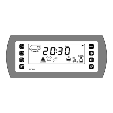
"Touch the sensor for Check starter battery voltage.
The voltage of the starter battery is displayed.
3.6 Checking tank levels
"Touch Check tank level sensor:
-- W a t e r o r
-- Waste water
FThe level of the relevant tank is displayed:
-- Water: 100%, 75%, 50%, 25%;
The tank is empty if the 25% LED flashes.
-- Waste water: 100%, 75%, 50%, 25%

Operating Instructions Operator and control panel LT 45X
10 Date: 29.05.2020 9310330 BA / EN
3.7 Troubleshooting and remedies
3.7.1 Alarms
YATTENTION!
Total discharge results in damage to the leisure area battery:
FA low battery charge, indicated by low voltage, must be prevented.
FCheck the voltage regularly (see Section 3.5)
YIt is best to carry out checks in the morning before 12V consumers are
switched on.
Alarm Possible cause Remedy
When the system is swit-
ched off:
-- Voltage of the leisure
area battery has fallen
below 11.4V.
W
i
t
h
s
y
s
t
e
m
s
w
i
t
c
h
e
d
o
n
Switch off all 12V consu-
mers.
With system switched on
and check of leisure area
battery voltage:
-- Voltage of the leisure
area battery has fallen
below 11.0V.
Applicable for both cases:
Risk of total discharge of
the leisure battery.
Charge the battery:
-- Start engine
or
-- connect to 230V power
supply
3.7.2 Faults
The majority of power supply system faults are caused by blown fuses (refer
to the instruction manual for the relevant EBL ... / CSV ... power supply for
information on voltage distribution and .
Please contact our customer service team if you cannot rectify a fault using
the following table.
If this is not possible (such as when you are abroad), you can have the elec-
trical vehicle system repaired at a specialist workshop. In this case, you
must ensure that the warranty is not invalidated by incorrect repairs being
carried out. Schaudt GmbH will not accept any liability for damage resulting
from such repairs.
Fault Possible cause Remedy
12V supply does not
function (or some areas
t
d
)
12V main switch is
switched off.
12V main switch must be
switched on.
(
are not powered). Fuse blown. Refer to the operating
manual for the EBL...
power supply . .
12V indicator LED (green)
does not light up.
12V main switch is
switched off.
12V main switch must be
switched on.
g
p
Leisure area battery not
charged.
Charge the leisure area
battery.
Fuse blown. Refer to the operating
manual for the EBL... .
Flat vehicle fuses

Operating Instructions Operator and control panel LT 45X
11
Date: 29.05.2020
9310330 BA / EN
Fault RemedyPossible cause
Leisure area battery is flat. Leisure area battery is
discharged.
Immediately charge the
leisure area battery.
The leisure area battery is
damaged beyond repair if
left totally discharged for a
lengthy period.
The battery can be
discharged by inactive
consumers.
Fully charge the leisure
battery before taking the
motorhome out of service
for a longer period.
The mains indicator LED
(green) does not light up
even though the 230V
i
l
i
The mains connection is
dead.
Check the mains
connection (e.g. camping
site).
g
mains supply is
connected. Circuit breaker or earth
leakage circuit breaker in
the vehicle (in front of
power supply) has
triggered or is disabled.
Reset the vehicle circuit
breaker or earth leakage
circuit breaker.
3.8 Switching off
"Touch the sensor for the main 12V ON/OFF switch
FThe green indicator LED goes out.
FThe 12V leisure area supply is switched off.
The refrigerator controller is an exception. It also works when the 12V power
supply is switched off, and as soon as a battery is connected or mains vol-
tage applied.
3.9 Closing down the system
The system should be switched off if the vehicle is not being used for a leng-
thy period, such as during the winter.
"Disconnect the leisure area battery from the 12V on-board supply; to do
this:
"Disable the battery cut-off switch of the relevant power supply
or
"Disconnect the battery terminals (depending on power supply)
YAlso refer to the operating manual for the relevant power supply (EBL ...).
4 Maintenance
The LT 45X control panel requires no maintenance.
Clean the device with a soft, slightly damp cloth and mild detergent. Never
use spirit, thinners or similar substances. Do not allow fluid to penetrate into
the LT 45X control panel.
No part of this manual may be reproduced, translated or copied without ex-
press written permission.
Cleaning
E

Operating Instructions Operator and control panel LT 45X
12 Date: 29.05.2020 9310330 BA / EN
Appendix
A Block diagram/wiring diagram
Circuit board
1
2
3
4
5
6
1
2
3
4
5
1
2
3
Full
3/4
1/2
1/4
Base
n.c.
Full
3/4
1/2
1/4
Base
MicroFit ST2,
e.g. Molex 3.0
No. 43645-0600
Rear
Top
MicroFit ST3,
e.g. Molex 3.0
No. 43645-0500
MicroFit ST1
e.g. Molex 3.0
No. 43025-1000
12 V -- OFF
12 V -- ON
12 V -- Check
Mains
-- Sensor WB
Waste water tank
Water tank
+ Sensor WB
SB
Pump
Light
AUX 4
5
6
7
8
9
10
B Customer service
Schaudt GmbH, Elektrotechnik & Apparatebau
Planckstraße 8
88677 Markdorf, Germany
Phone: +49 7544 9577-16
Email: kundendienst@schaudt-gmbh.de
Web: www.schaudt-gmbh.de
Returning a faulty device:
"Complete and enclose the fault report, see Appendix C.
"Send it to the addressee (free delivery).
Customer service
Send in device

Operating Instructions Operator and control panel LT 45X
13
Date: 29.05.2020
9310330 BA / EN
C Fault report
In the event of damage, please fill in the fault report and send it with the
faulty device to the manufacturer.
Device type: _______________________
Item no.: _______________________
Vehicle: Manufacturer: _______________________
Model: _______________________
Own installation? Yes -No -
Upgrade? Yes -No -
There is the following defect:
(please tick)
-Battery not being charged during power operation
-Battery voltage not displayed
-Electrical consumers do not work -- which?
-General malfunction of switch panel
-Persistent fault
-Intermittent fault/loose contact
Other comments:

Operating Instructions Operator and control panel LT 45X
14 Date: 29.05.2020 9310330 BA / EN
(Blank page)

ESchaudt GmbH, Elektrotechnik und Apparatebau, Planckstraße 8, 88677 Markdorf, Germany, Tel. +49 7544 9577-0, Fax +49 7544 9577-29, www.schaudt--gmbh.de
9310330 BA / DE Datum: 29.05.2020
Bedienungsanleitung
Bedien- und Kontrollpanel LT 45X
Inhaltsverzeichnis
1 Einleitung 2..............................................
2 Verwendungszweck und Funktion 5.........................
3 Bedienung 6.............................................
3.1 Aufbau 6................................................
3.2 Inbetriebnahme 7.........................................
3.3 Einschalten 7............................................
3.4 Schalten von Verbrauchern 7..............................
3.5 Batteriespannung abfragen 8...............................
3.6 Tankfüllstände abfragen 9.................................
3.7 Fehlersuche und Abhilfe 10.................................
3.8 Ausschalten 11............................................
3.9 Stilllegen 11..............................................
4 Wartung 11...............................................
Anhang 12...............................................

Bedienungsanleitung Bedien- und Kontrollpanel LT 45X
2Datum: 29.05.2020 9310330 BA / DE
1 Einleitung
Diese Bedienungsanleitung enthält wichtige Hinweise zum sicheren Betrieb
von Geräten der Firma Schaudt.
Die Bedienungsanleitung im Fahrzeug immer mitführen.
YACHTUNG!
Die Nichtbeachtung dieses Zeichens kann zu Schäden am Gerät oder an
angeschlossenen Verbrauchern führen.
Die Bedien- und Kontrollpanels LT 45X unterscheiden sich in ihrer Ausstat-
tung und ggf. in der Darstellung der Symbole.
YÜber diese Dokumentation werden alle Bedien- und Kontrollpanels
LT 45X abgedeckt. Die nachfolgende Tabelle gibt einen Überblick über
die Ausstattungsmerkmale.
Typ Frontplatte
12 V EIN /AUS
Netzanzeige
Spannungsanzeige
Wohnraumbatterie
Spannungsanzeige
Starterbatterie
Füllstandsanzeige
Wassertank
Füllstandsanzeige
Abwassertank
Pumpenschalter
Schalter Licht
Schalter AUX
LT450 X X X X X X X X X*
LT451 X X X X X X
LT452 X X X X X X X
Ausstattung

Bedienungsanleitung Bedien- und Kontrollpanel LT 45X
3
Datum: 29.05.2020
9310330 BA / DE
Typ
Schalter AUX
Schalter Licht
Pumpenschalter
Füllstandsanzeige
Abwassertank
Füllstandsanzeige
Wassertank
Spannungsanzeige
Starterbatterie
Spannungsanzeige
Wohnraumbatterie
Netzanzeige
12 V EIN /AUS
Frontplatte
LT452* X X X X X X X*
LT453 X X X X X X X
LT454 X X X X X

Bedienungsanleitung Bedien- und Kontrollpanel LT 45X
4Datum: 29.05.2020 9310330 BA / DE
Typ
Schalter AUX
Schalter Licht
Pumpenschalter
Füllstandsanzeige
Abwassertank
Füllstandsanzeige
Wassertank
Spannungsanzeige
Starterbatterie
Spannungsanzeige
Wohnraumbatterie
Netzanzeige
12 V EIN /AUS
Frontplatte
LT455 X X X X X X
* Symbol “Multimedia” statt AUX

Bedienungsanleitung Bedien- und Kontrollpanel LT 45X
5
Datum: 29.05.2020
9310330 BA / DE
2 Verwendungszweck und Funktion
Das Bedien- und Kontrollpanel LT 45X ist das zentrale Bediengerät für die
Stromversorgung EBL ..., die alle 12-V-Verbraucher in der elektrischen An-
lage an Bord des Fahrzeugs versorgt. Sie befindet sich normalerweise in der
Nähe der Tür im oberen Bereich des Fahrzeugs an einer gut zugänglichen
Stelle.
+--
+--
Bedien- und
Kontrollpanel
LT 45X
Stromversorgung
EBL ...
Starterbatterie
Beleuchtung
Pumpe
Heizung
etc.
230 V AC
12 V VerbraucherWohnraumbatterie
Wassertank
Abwassertank
Bild 1 Energieversorgungssystem an Bord
In Bild 1 ist der prinzipielle Aufbau der elektrischen Anlage an Bord eines
Fahrzeugs dargestellt.
Ein Bedien- und Kontrollpanel LT 45X hat die Aufgabe, die 12-V-Versorgung
für das Fahrzeug ein- bzw. auszuschalten und die Batteriespannung, Tank-
füllstände sowie den Anschluss an die Netzversorgung (230 V) anzuzeigen.
Für den Betrieb muss eine Stromversorgung EBL ... angeschlossen sein.
Diese stellt die 12 V-Versorgung für die Geräte des Fahrzeugs bereit und
lädt die Batterie.
Es sind folgende Anschlussmöglichkeiten vorhanden:
FStromversorgung EBL ...
FWassertanksonde
FAbwassertanksonde oder -sensoren
Verwendungszweck
Funktion
Geräte des Systems

Bedienungsanleitung Bedien- und Kontrollpanel LT 45X
6Datum: 29.05.2020 9310330 BA / DE
3 Bedienung
3.1 Aufbau
Das Bedien- und Kontrollpanel LT 45X ist zum Einbau in einen Schrank oder
in eine Wand vorgesehen.
2
1
2.12.2 2.6 2.7
1.1
1.5
1.7
1.6
1.2
1.3
1.4
1.8
2.32.42.5
Bild 2 Aufbau Bedien- und Kontrollpanel LT 45X
1Sensor-Tastfelder 2Anzeigeelemente
-- -- 2.1
LED Netzkontrolle (gelb):
Die LED leuchtet, wenn Netzspannung am
Eingang zur Netzversorgung des Fahrzeugs
anliegt (siehe auch Bedienungsanleitung der
zugehörigen Stromversorgung EBL ... , Kapi-
tel “Inbetriebnahme”).
1.1
Hauptschalter 12 V EIN / AUS:
Ein- bzw. Ausschalten der 12-V-Versorgung
des Fahrzeugs 2.2
Kontroll-LED (grün):
Anzeige: 12 V Versorgung Fahrzeug einge-
schaltet
1.2
Pumpenschalter:
Ein- bzw. Ausschalten der 12-V-Versorgung
für die Wasserpumpe 2.3 Kontroll-LED (gelb):
Anzeige: Pumpenversorgung eingeschaltet
1.3
Versorgung Licht:
Ein- bzw. Ausschalten der 12-V-Versorgung
für die Wohnraumbeleuchtung 2.4
Kontroll-LED (gelb):
Anzeige: Versorgung der Beleuchtung einge-
schaltet
1.4
Versorgung AUX:
Ein- bzw. Ausschalten der 12-V-Versorgung
AUX (z. B. für Radio oder TV) 2.5 Kontroll-LED (gelb):
Anzeige: Versorgung AUX eingeschaltet
1.5 Abfrage Batteriespannung Wohnraumbatterie
2
6
8 LEDs (2 rot -- 2 gelb -- 4 grün):
A
n
z
e
i
g
e
B
a
t
t
e
r
i
e
s
p
a
n
n
u
n
g
i
n
8
S
t
u
f
e
n
u
n
d
1.6 Abfrage Batteriespannung Starterbatterie
2
.
6
A
nze
i
ge
B
a
t
t
er
i
espannung
i
n
8
S
t
u
f
en un
d
Warnung vor Tiefentladung.
1.7 Abfrage Tankfüllstand Wassertank
2
7
8 LEDs (blau):
A
n
z
e
i
g
e
d
e
r
T
a
n
k
f
ü
l
l
s
t
ä
n
d
e
v
o
n
W
a
s
s
e
r
-
u
n
d
1.8 Abfrage Tankfüllstand Abwassertank
2
.
7
A
nze
i
ge
d
er
T
an
k
f
ü
l
l
s
t
ä
n
d
evon
W
asser- un
d
Abwassertank in vier Stufen.
Other manuals for LT 45 Series
1
This manual suits for next models
6
Table of contents
Languages:
Other Schaudt Control Panel manuals