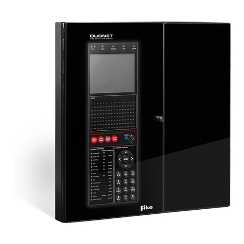
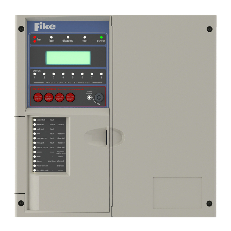
Fike TWINFLEX SRP 100-0001 User manual

26-1361-02
TWINFLEX®SRP
Single Flood Zone Fire Suppression System
Control Panel
100-0001
(Suitable for TWINFLEX®SRP control panels from V01.000)
Control Panel Engineering and
Commissioning Manual
(TO BE RETAINED BY THE COMMISSIONING ENGINEER)

TWINFLEX®SRP Control Panel Engineering and Commissioning Manual
2
Fike’s policy is one of continual improvement and the right to change a specification at any time without notice is reserved. Whilst every
care has been taken to ensure that the contents of this document are correct at time of publication, Fike shall be under no liability
whatsoever in respect of such contents.
Due to the complexity and inherent importance of a life risk type system, training on this equipment is essential and commissioning should
only be carried out by competent persons.
Fike cannot guarantee the operation of any equipment unless all documented instructions are complied with, without variation.
E&OE.
TWINFLEX®, Mulitpoint, Fike and Fike Corporation are registered trademarks of Fike Corporation and its subsidiaries. All other trademarks,
trade names or company names referenced herein are the property of their respective owners.
Fike equipment is protected by one or more of the following patent numbers: GB2426367, GB2370670, EP1158472, PT1035528T,
GB2346758, EP0917121, GB2329056, EP0980056, GB2325018, GB2305284, EP1174835, EP0856828, GB2327752, GB2313690
© 2015 Fike Safety Technology Ltd. All rights reserved. Document issued January 2016.

TWINFLEX®SRP Control Panel Engineering and Commissioning Manual
3
Contents
GLOSSARY OF TERMS.........................................................................................................5
INTRODUCTION.....................................................................................................................6
System Design......................................................................................................................................... 6
Equipment Guarantee ............................................................................................................................. 6
Anti-Static Handling Guidelines............................................................................................................. 6
Warning .................................................................................................................................................... 6
EMC........................................................................................................................................................... 7
THE TWINFLEX®SRP SYSTEM ............................................................................................7
CONTROL PANEL..................................................................................................................9
Mounting the Control Panel.................................................................................................................... 9
Physical Dimensions............................................................................................................................... 9
Power Supply Unit................................................................................................................................. 11
General Assembly ................................................................................................................................. 12
Topology & Cabling............................................................................................................................... 13
System Wiring Schematic..................................................................................................................... 14
Control Panel Connections .................................................................................................................. 15
Main Display Board .................................................................................................................... 15
Releasing Connector Board .......................................................................................................16
Ethernet...................................................................................................................................... 17
Write Protect / Write Enable Switch............................................................................................ 17
USB-B......................................................................................................................................... 17
Buzzer Link: J1........................................................................................................................... 17
LCD Contrast: R4 .......................................................................................................................17
RSI Peripheral Bus Connections: A1, B1, SCRN or A2, B2, SCRN ..........................................18
Programmable Inputs 1-5: MI# +, MI# -, SCRN .........................................................................19
Fault Relay: C, N/C, N/O ............................................................................................................20
Programmable Relays 1-4: C, N/C, N/O..................................................................................... 20
Monitored Outputs 1 -3: MO# +, MO# -, SCRN..........................................................................21
Device Zones: Z1 - Z4 (TWINFLEX®Devices)...........................................................................23
Device Zones: Z1 - Z4 (Conventional Devices).......................................................................... 24
Zones: Z1 - Z4 RELEASING OPERATION (IVO OR SOLENOID) ............................................24
Auxiliary Power: AUX PWR 1-2, +, -, SCRN..............................................................................25
Battery: BAT+, BAT-...................................................................................................................25
Power Supply: VPSU+, VPSU-, EARTH.................................................................................... 26
Output De-rating......................................................................................................................... 26
Mains Input Wiring...................................................................................................................... 26
GENERAL OPERATION OF CONTROL PANEL.................................................................27
Zone Detection & Releasing Operation...................................................................................... 27

TWINFLEX®SRP Control Panel Engineering and Commissioning Manual
4
Hold State / Hold Sound Patterns...............................................................................................27
Auto/Manual operation ............................................................................................................... 28
Extinguishant Flow, Discharge Pressure Input Operation.......................................................... 28
Power Start Up with batteries only .............................................................................................28
Control Panel Front ............................................................................................................................... 29
LED Indication........................................................................................................................................ 29
Fire Alarm Controls............................................................................................................................... 32
System Controls.................................................................................................................................... 32
Extinguishant Release Controls .......................................................................................................... 32
Information Window .............................................................................................................................. 33
Access Levels and Codes .................................................................................................................... 33
Enter An Access Code ............................................................................................................... 34
Access Level 1 (Normal): ...........................................................................................................35
Access Level 2A (User):............................................................................................................. 37
Access Level 2B (Supervisor): ................................................................................................... 41
Access Level 3 (Engineer):.........................................................................................................46
INSTALLATION AND COMMISSIONING.............................................................................61
Installation 1st Stage.............................................................................................................................. 61
Maximum Cable Lengths ...................................................................................................................... 61
Installation 2nd Stage............................................................................................................................. 61
Commissioning...................................................................................................................................... 62
End User Training.................................................................................................................................. 62
Maintenance........................................................................................................................................... 62
FAULT FINDING...................................................................................................................63
Summary of Faults ................................................................................................................................ 63
Intermittent Zone Fault.......................................................................................................................... 63
Permanent Zone Faults......................................................................................................................... 63
False Alarms .......................................................................................................................................... 64
General Faults........................................................................................................................................ 64
Finding Zone Faults............................................................................................................................... 65
ADVANCED CONNECTIONS...............................................................................................66
Magnetic Door Hold Units..................................................................................................................... 66
TECHNICAL DATA...............................................................................................................67
Control Panel Specification.................................................................................................................. 67
Control Panel Ratings........................................................................................................................... 67
Control Panel Fuses and Protection.................................................................................................... 68
Factory Default Settings & Profiles, .................................................................................................... 69
BATTERY CALCULATIONS ................................................................................................71

TWINFLEX®SRP Control Panel Engineering and Commissioning Manual
5
INSTALLATION CHECKLIST...............................................................................................72
Stage 1.................................................................................................................................................... 72
Stage 2.................................................................................................................................................... 72
COMMISSIONING CHECKLIST ...........................................................................................73
Step 1...................................................................................................................................................... 73
Step 2...................................................................................................................................................... 73
Step 3...................................................................................................................................................... 73
Step 4...................................................................................................................................................... 73
CABLE CONTINUITY & INSULATION TEST RESULTS.....................................................74
FIRE ALARM SYSTEM NOTICE ..........................................................................................75
FIRE ALARM USER NOTICE...............................................................................................76
ENGINEERS NOTES............................................................................................................77
TECHNICAL SUPPORT........................................................................................................78
Glossary Of Terms
Acronym
Description
Acronym
Description
ASD
Automatic Smoke Detector
MCP
Manual Call Point
CIE
Control & Indicating Equipment
O/C
Open Circuit
DIVA
Direct Impulse Valve Actuator
O/P
Output
EOL
End Of Line
RSI
Remote Status Indicator
I/O
Input Output
S/C
Short Circuit
I/P
Input
SRM
Solenoid Releasing Module
IRM
Impulse Releasing Module
SRP
Single-hazard Releasing Panel
IVO
Impulse Valve Operator
OSP
On Site Programmer

TWINFLEX®SRP Control Panel Engineering and Commissioning Manual
6
Introduction
This Manual is intended as a guide to the engineering and commissioning principles of the TWINFLEX®
SRP 2-wire Fire Detection and Alarm system and covers the system hardware information only.
Due to the complexity and inherent importance of a system covering a ‘Life Protection Risk’, training on
this equipment is essential and commissioning should only be carried out by competent and approved
persons. For further details of the availability of commissioning services, please contact your supplier.
System Design
This document does not cover Fire Alarm system design and a basic understanding is
assumed.
Knowledge of BS5839: Pt 1: 2002: Fire Detection and Alarm Systems for Buildings
and BS 7273 Pt 1 : 2006 Code of Practice for the operation of fire protection
measures is essential.
It is strongly recommended that a suitably qualified and competent person is consulted in
connection with the Fire Alarm System design and that the entire system is commissioned
in accordance with the current national standards and specifications.
Equipment Guarantee
The equipment carries no warranty unless the system is installed, commissioned and
serviced in accordance with this manual and the relevant standards by a suitably qualified
and competent person or organisation
Anti-Static Handling Guidelines
Immediately prior to handling any PCBs or other static sensitive devices, it is essential to
ensure that a personal connection to earth is made with an anti-static wrist-strap or
similar apparatus.
Always handle PCBs by their sides and avoid touching any components. PCBs should also
be stored in a clean dry place, which is free from vibration, dust and excessive heat and is
protected from mechanical damage.
Warning Do not attempt to install this equipment until you have fully read and understood
this manual.
Failure to do so may result in damage to the equipment and could invalidate the warranty.
For technical support please contact your distributor. Do not call the Fike Safety
Technology support department unless your distributor has first given their advice and
attempted to rectify the issue.
Technical support will not be available if the instruction manual has not been read and
understood. Please have this instruction manual available whenever you call for technical
support.
!
!
!
!

TWINFLEX®SRP Control Panel Engineering and Commissioning Manual
7
EMC This equipment when installed is subject to the EMC directive 2004/108/EC. It is also
subject to UK Statutory Instrument 2006 No. 3418.
To maintain EMC compliance, this system must be installed as defined within this manual.
Any deviation from this renders the installer liable for any EMC problems that may occur
either to the equipment or to any other equipment affected by the installation.
The TWINFLEX®SRP System
The TWINFLEX®SRP system is a single flood zone panel with an intelligent ‘2-wire’ system utilising a
conventional type cabling format. The system is classed as ‘Analogue non-addressable’ due to the
architecture used within the design. All field devices including sounders can be connected to the zone
via a common 2-core screened cable. The devices communicate with the control panel using the
TWINFLEX®data protocol.
The TWINFLEX®SRP panel monitors each zone for detector head removal, device fault, ‘End of line’
fault and open or short circuit fault.
Devices or detector heads should not be removed with the zone switched on.
Switch off the zone (at access level 3) before removing any devices or detector
heads from that zone.
Twinflex detector heads must only be removed using the correct head removal
tool, 25-0046-201. Removing detector heads without using the correct tool will
result in damage to the head / detector base.
Every device has an inbuilt ‘End of line’ signal, which may be activated as required. All setting options
are configured using the DIL switches fitted to the device.
Do not use a resistor or capacitor or any other 3rd party ‘End of line’ module for
‘End of line’.
The TWINFLEX®SRP control panel also provides three monitored outputs that may be configured as
notification (conventional sounder) circuits or 2 notification (conventional sounder) circuits and 1
releasing circuit, four volt free common relays and a volt free common fault relay. There are also five
multifunction latching/non-latching inputs.
The TWINFLEX®SRP control panel incorporates an integral power supply unit and requires 2 x 12V
12.0Ah batteries to provide up to 72 hour standby times depending on system loading (refer to
Technical Data for further information). Standby battery calculations may be made using the
TWINFLEX®SRP Panel Battery & Loading Unit Calculation Sheet (document no. 26-1389).
Unlike most conventional fire alarm systems, which require separate pairs of cables for detector zones
and sounder circuits, the TWINFLEX®SRP system requires one 2-core screened cable for each zone
to accommodate both detection devices and sounders. Furthermore, sounders are incorporated within
the detector to reduce system components and simplify installation.
The zones can also be programmed to be conventional zones and use conventional detectors.
MCPs must not be used on conventional zones. Conventional zones cannot distinguish
between an MCP or detection activation so if needed should be connected to a monitored input.
An MCP activation will therefore not initiate an extinguishing release procedure on a conventional zone.
!

TWINFLEX®SRP Control Panel Engineering and Commissioning Manual
8
The TWINFLEX®SRP panels include some features described in EN54-2 as ‘optional functions with
requirements’. These are:-
Output to fire alarm devices EN54-2 Clause 7.8
Output to fire protection equipment, type A EN54-2 Clause 7.10.1
Delays to outputs EN54-2 Clause 7.11.1
Zone test facility EN54-2 Clause 10
Input/output facilities EN54-2 Clause 7.11.1
The TWINFLEX®SRP panel includes the following compulsory features required by EN12094-1:
Input signal to manually trigger EN12094-1 Section 4.3.2a
Transmission of extinguishing signal EN12094-1 Section 4.3.2b
Activation of alarm devices after triggering EN12094-1 Section 4.3.2c
Unambiguous indication of each condition EN12094-1 Section 4.2.2d
Transmission of incorrect status and fault warning EN12094-1 Section 4.3.2e
Transmission of the released condition EN12094-1 Section 4.3.2f
The TWINFLEX®SRP panel includes the following optional features with requirements allowed by
EN12094-1:
Delay of extinguishing signal up to 60 seconds EN12094-1 Section 4.17
Signal representing flow of extinguishing agent EN12094-1 Section 4.18
Monitoring of status by way of a low pressure switch input EN12094-1 Section 4.19
Emergency hold device to allow delay to be extended EN12094-1 Section 4.20
Control of flooding time EN12094-1 Section 4.21
Manual only mode to disable release EN12094-1 Section 4.23
Triggering of equipment outside the system EN12094-1 Section 4.26
Control of extended discharge EN12094-1 Section 4.28
Activation of alarm devices to indicate pre-discharge and release EN12094-1 Section 4.30
These facilities are described elsewhere in this manual.

TWINFLEX®SRP Control Panel Engineering and Commissioning Manual
9
Control Panel
Mounting the Control Panel
First identify the proposed location for the control panel. Ensure that the control panel will be easily
accessible and that account is taken of any subsequent work that may affect access.
The control panel should be located at the most likely point of access for the fire services. It should be
mounted on a flat, vertical wall at a height where the indicators may be seen without difficulty.
Do not locate the control panel at high level where stepladders or other access equipment may
be required, in spaces with restricted access, or in a position that may require access panels to
be removed.
Do not locate the control panel where extremes of temperature or humidity may occur, or where
there is any possibility of condensation or water ingress.
Like all electronic equipment, the control panel may be affected by extreme environmental conditions.
The position selected for its installation should therefore be clean and dry, not subjected to high levels
of vibration or shock and at least 2 metres away from any pager or radio transmitting equipment.
Ambient temperatures should be within the range given within the Technical Data section, e.g. not
directly over a radiator or heater.
In common with all microprocessor-controlled panels, the control panel may operate erratically or may
be damaged if subjected to lightning-induced transients. Proper earth/ground connections will greatly
reduce susceptibility to this problem.
Physical Dimensions
The control panel back box is designed as a dual-purpose surface or flush mount unit.
Surface Mounting: Utilize the three through holes in the back of the back box to secure it to the
mounting surface with suitable anchors
Flush Mounting: Cut an opening in the wall to fit the back box dimensions, not to include the 14mm
flange, and secure the box in place utilizing the through holes provided on the sides of the back box
with suitable anchors.

TWINFLEX®SRP Control Panel Engineering and Commissioning Manual
10
NOTE: The 14mm flange facilitates flush mounting. To allow installation of the main front moulding, this
flange must be flush with the mounting surface and not recessed into it.

TWINFLEX®SRP Control Panel Engineering and Commissioning Manual
11
Power Supply Unit
The mains supply should be dedicated to the Fire Alarm Panel and should be clearly labelled ‘FIRE
ALARM: DO NOT SWITCH OFF’ at all isolation points. The Fire Alarm Panel 230V AC supply requires
a 3 amp fused un-switched spur with local isolation and fixed wiring between 0.75 mm2and 2.5 mm2,
terminated into the fused terminals provided in the back box. The main PCB is supplied via a Switch
Mode Power Supply located behind the connector board mounting plate. Only the power supply
provided in the unit may be used to power the control panel. Both mains termination and location of
power supply are shown below.
The control panel requires standby batteries. Fike recommends 2 x Yuasa YUCEL Y12-12 or equivalent.
The sealed lead acid batteries should be installed according to the following diagram. These are to be
sited in the control panel back box using the provided clamps. The batteries should be connected in
series using the connection leads supplied See the section entitled Control Panel Connections for panel
connections.
When fitting new batteries the total battery voltage must not be less than 21.5V. If the battery voltage is
less than 21.5V the charger will assume that they are faulty and will not charge them.
Note that the charging circuit will be in its high impedance state (approximately 3V DC) if no batteries,
faulty batteries, or only one battery is connected. The full 27V DC (nominal) charging voltage should be
present if the correct batteries are connected.
If the system shows a charger or battery fault on first power up, leave the system to charge the batteries
for 5-6 hours.
In order to test for correct operation of the batteries, remove the mains 230V AC fuse and allow the
batteries to settle from their charging voltage for approximately 5 minutes. The battery voltage should
then be measured using an electronic test meter and a voltage greater than 24V DC should be seen.

TWINFLEX®SRP Control Panel Engineering and Commissioning Manual
12
Note that batteries are electrically live at all times and great care should be taken to ensure that the
terminals are never presented with a short circuit. Care should be taken at all times, especially during
transit, installation and normal use.
Batteries no longer required should be disposed of in a safe and environmentally friendly manner by the
manufacturer or a suitable recycling service. They should never be incinerated or placed in normal
rubbish collection facilities.
General Assembly

TWINFLEX®SRP Control Panel Engineering and Commissioning Manual
13
Topology & Cabling
All system wiring should be installed to comply with BS 5839: Pt 1: 2002 + A2 : 2008 and BS 7273 Pt 1
: 2006 and any other standards relevant to the area or type of installation. A cable complying with the
BS 5839: Pt 1: 2002 + A2 : 2008 Category 1 (cables required to operate for prolonged periods during
fire conditions) is required. This must be a 2-core 1.5mm2screened fire resistant cables (i.e. MICC,
FP200, Firetuff, Firecell, Lifeline or equivalent).
Each zone requires a separate 2-core radial circuit from the control panel to the furthest point of the
zone, to a maximum of 500 metres.
In order to protect against possible data corruption it is important to ensure the following points are
adhered to:
1. Ferrites must be fitted to all four zones. See diagram below
These will be supplied with the panel.
2. The cable screen must be connected to the SCRN terminal for each circuit at the control
panel only.
3. The cable screen must not be connected to earth/ground at any point other than the control
panel (at the SCRN terminal provided, not at any earthing point). Do not connect the
screen to a device back box other than one supplied by Fike.
4. The cable screen continuity must be maintained at every point of the circuit, using the
terminals provided or a suitable connection block.
5. Do not use a 4-core cable as a circuit zone in and zone out, due to the possibility of data
corruption. It is essential that two 2-core screened cables are used if this is required.
Refer to the following System Wiring Schematic for further details.
Wurth Part No 7427009
ferrites

TWINFLEX®SRP Control Panel Engineering and Commissioning Manual
14
System Wiring Schematic
The four zones can be configured in menu option 9 as follows:
Off, Zone not in use.
Twinflex, Twinflex detection zone, as shown in the schematic below
Conventional, Conventional detection zone
Release IRM, Impulse releasing module zone
Release SRM, Solenoid releasing module zone
The following schematic may prove useful as an aid to understanding the cable requirements for the
system;
KEY TO SYMBOLS
TWINFLEX®Multipoint
TWINFLEX®Multipoint with Sounder TWINFLEX®Manual Call Point
1-4 TWINFLEX®SRP
zones. Cabled in 2 core
1.5mm2Screened cable
complying with BS 5839:
Pt 1: 2002 Category 1.
Note: No EOL device is
required as EOL is set at
the end device.
3 x Monitored Outputs,
programmable as for
various panel states.
Requires 10kΩ EOL for
notification or 3.3KΩ for
releasing.
4 x Programmable Relays
Max 2A @ 30V.
Fault Relay MAX 1A
@ 30V.
230 V 50Hz AC power
supply requires a
dedicated supply with a
local un-switched fused
spur in accordance
with BS5839 pt1: 2002
5 x monitored Inputs
programmable for multiple
functions.
Requires 3.3KΩEOL.
Requires a 470Ω or 680Ω
resistor to activate.
2 auxiliary power outputs
(resettable or non-
resettable)
Remote Status
Indicator (8 max.)

TWINFLEX®SRP Control Panel Engineering and Commissioning Manual
15
Control Panel Connections
Main Display Board
TERMINAL
DESCRIPTION
SW1
Write Protect/Write Enable Switch
USB
USB-B connection for pc link
J1
Buzzer Link Jumper
R4
LCD Contrast

TWINFLEX®SRP Control Panel Engineering and Commissioning Manual
16
Releasing Connector Board
TERMINAL
DESCRIPTION
RSI Communication
A1
Positive connection for RSI communication
B1
Negative connection for RSI communication
SCRN
Screen connection for RSI communication
A2
Positive connection for RSI communication
B2
Negative connection for RSI communication
SCRN
Screen connection for RSI communication
MONITORED I/P 1-5
MI# +
Monitored Input positive connection
MI#-
Monitored Input 0V connection
SCRN
Field cable screen connection
MONITORED O/P 1-3
MO# +
Programmable Output positive connection
MO# -
Programmable Output 0V connection
SCRN
Field cable screen connection
ZONES 1 - 4
Z # +
Device zone positive connection
Z # -
Device zone 0V connection
SCRN
Field cable screen connection
FAULT RELAY
N/C
Normally closed fault contact
N/O
Normally open fault contact
COM
Common fault contact
PROG RELAY 1-4
N/C
Normally closed fire contact
N/O
Normally open fire contact
COM
Common fire contact
AUX SUPPLY
+
Aux power positive connection
-
Aux Power 0V connection
SCRN
Field cable screen connection
BATTERY
VBATT +
24V DC 12Ah Battery positive connection
VBATT -
24V DC 12Ah Battery 0V connection
PSU
VPSU +
31V DC Input from Switch Mode PSU
VPSU -
0V DC Input from Switch Mode PSU
Earth
Earth input from Switch Mode PSU
Note: References to voltages are nominal values

TWINFLEX®SRP Control Panel Engineering and Commissioning Manual
17
Ethernet
This port on the panel is reserved for future use.
Write Protect / Write Enable Switch
The write protect / write enable switch is a two position switch which is normally set to stop options in the
engineer menu from being inadvertently changed.
Note: when this switch is in the on position the general fault LED will flash to remind the Engineer the switch is
on.
ON Switch in
OFF position
Write Protect Mode:
In the OFF position, as shown (left), engineering options
may be viewed but no configuration changes made.
ON Switch in
ON position
Write Enable Mode:
If configuration changes are to be made, this switch needs
to be in the ON position as shown (left).
USB-B
The panel is fitted with an on board USB-B connector. This is to provide
communication via a suitable USB lead to a PC for programming of panel
options using the TWINFLEX®SRP OSP configuration software.
Buzzer Link: J1
Linking J1 will disable the panel buzzer. The buzzer will remain disabled whilst the link is in place. Warning –
To comply with EN54 and BS5839: Pt1: 2002 this link must be left OPEN.
LCD Contrast: R4
The LCD contrast may be adjusted by rotating the screw on the variable resistor, located in the upper right hand
corner of the main PCB. Rotate anticlockwise to reduce the contrast (lighten text). Rotate clockwise to
increase the contrast (darken text).

TWINFLEX®SRP Control Panel Engineering and Commissioning Manual
18
RSI Peripheral Bus Connections: A1, B1, SCRN or A2, B2, SCRN
These ports on the panel are for connections to a Remote Status Indicator (RSI) device (Maximum 8
devices). This is an RS-485 connection operating at 57.6 kbps.
NOTES
1. An RSI must be setup to be supervised in order to operate with the SRP. This is done at Access Level
3 (Engineer) at Engineer Menu 13. RSI SUPERVISION.
2. A 120Ω End of Line (EOL) resistor must be fitted across A and B of the last RSI on the network.

TWINFLEX®SRP Control Panel Engineering and Commissioning Manual
19
Programmable Inputs 1-5: MI# +, MI# -, SCRN
Activate On Closing Contact
Activate On Opening Contact
Note: When a monitored input is configured as a normally closed extinguishant flow input, connecting a
normally open switch will cause the panel to go into a release state.
Likewise when a monitored input is configured as a normally open extinguishant flow input, connecting
a normally closed switch will cause the panel to go into a release state.
Maximum Voltage at contacts, 3.3 Volts, Maximum current 0.72mA.
Minimum Voltage at contacts, 0 Volts.
Monitored Inputs can be configured so they activate on an opening or a closing contact using a 680Ω or
470Ω ‘firing’ resistor. They also monitor for open and short circuit faults using a 3k3ΩEOL resistor.
Programmable inputs can be configured to initiate the following system-level events:
CONTROL EVENT
SILENCE ALARMS
DISABLEMENT
ALL SOUNDERS &
RESET SYSTEM
RELEASING OUTPUTS
SOUND ALARMS
RELAYS
SILENCE BUZZER
RELEASE EVENT
MANUAL RELEASE
REMOTE EVENT
REMOTE FIRE
HOLD
GENERAL FAULT
EXTINGUISHANT FLOW
MANUAL MODE
LOW PRESSURE
EXTRACT
Caution –the use of an input to disable the buzzer does not meet EN54-2
Note: Access to any input device connected to an SRP monitored input which has been configured to
activate one of the following functions needs to be protected by a locked enclosure or be
operated by a key switch to prevent unauthorised operation.
Silence Alarms
Sound Alarms
Reset System
Silence Buzzer
Manual Mode
Disablements
ON BOARD PCB FIELD CONNECTIONS
MI1 -
MI1 +
SCREEN
N/OCONTACT 3K3
Ohms
EOL
680
Ohms
SCRN
ON BOARD PCB FIELD CONNECTIONS
MI1 -
MI1 +
SCREEN
SCRN
N/C CONTACT 3K3
Ohms
EOL
680
Ohms

TWINFLEX®SRP Control Panel Engineering and Commissioning Manual
20
Fault Relay: C, N/C, N/O
The fault relay is derived from a single pole change over ‘volt-free’ relay contact which is not fault
monitored. The maximum contact current rating is 2A @ 24V DC. Inductive loads should be diode
protected to prevent back EMF causing damage to the relay contact.
The default setting for the fault relay causes the relay to operate as a Common Fault output where the
relay is de-energised in the fault condition and will remain so until the fault is cleared.
Programmable Relays 1-4: C, N/C, N/O
The relays are derived from a single pole change over ‘volt-free’ relay contact which is not fault
monitored. The maximum contact current rating is 2A @ 24V DC. Inductive loads should be diode
protected to prevent back EMF causing damage to the relay contact.
Programmable relays can be configured to activate during the following system-level states:
OUTPUT STATE
No State
Manual
Fault
Disablement
Hold
Extract
Release
Pre-Release
Alarm
Note:
Programmable relays set to activate on release must not be used to drive releasing devices. The
circuits connected to these relays are not monitored and will not follow the releasing alarm pattern.
When releasing outputs are disabled, Programmable Relays that are set as releasing are also disabled
but are not logged in the event log as being disabled.
ON BOARD PCB FIELD CONNECTIONS
NORMALLY CLOSED
NORMALLY OPEN
COMMON
ON BOARD PCB FIELD CONNECTIONS
NORMALLY CLOSED
NORMALLY OPEN
COMMON
Table of contents
Other Fike Control Panel manuals

Fike
Fike FIK-RA2000 Technical manual

Fike
Fike FIK-5496 User manual
Fike
Fike FCP-300 User manual
Fike
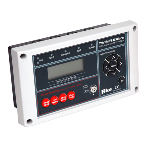
Fike TWINFLEXpro User manual
Fike
Fike FCP-75 User manual

Fike
Fike GB2426367 User manual
Fike
Fike FCP-2100 User manual
Fike
Fike FIK-RA100BD Technical manual
Fike
Fike CIE-A-200 User manual
Fike
Fike FCP-2100ECS User manual
Popular Control Panel manuals by other brands
Digital Monitoring Products
Digital Monitoring Products XT Series installation guide

iZone
iZone 310 manual
Komfovent
Komfovent DOMEKT series Installation and operation manual
DMP Electronics
DMP Electronics PC0128 installation guide
Bosch
Bosch D7024 Operation and installation guide

WAGO
WAGO PERSPECTO WP 57 QVGA manual


