Schenker READY Electron 60 User manual

1
OPERATION AND MAINTENANCE MANUAL
1. Introduction
1.1.General
1.2.Technical data
1.3.System description
2. Installation
2.1.General criteria and material required
2.2.Components mounting
2.3.Water intake
2.4.Hydraulic connections
2.5.Hydraulic diagram
2.6.Electric connections
3. Operating procedures
3.1. By-pass activation
3.2. First start-up procedure
3.3. Normal operating procedure
4. Maintenance
4.1. Shutdown procedure
4.2. Maintenance and recurrent inspections
4.3. Troubleshooting
5. Safety cautions
6. Most frequent operations summary table
7. Warranty
Rev. 2004

2
1. Introduction
1.1 General
Thank you for choosing a Schenker Watermaker, and we are sure that the plant will contribute
to make your cruises more comfortable and more pleasant.
As all the equipment aboard, the knowledge of operating and maintenance procedures allows to
use the system in the best way, and to guarantee a perfect functioning throughout the years.
We invite you to read carefully this manual and to keep it aboard for a quick reference.
The Modular plant, as alternative to the high pressure pumps of traditional plants, utilizes the
ENERGY RECOVERY SYSTEM patented device, which amplifies the pressure of common low
pressure pumps, and recoup all the hydraulic energy back from the membranes, allowing an high
energy efficiency and the possibility to supply the watermaker directly from the batteries. The
ENERGY RECOVERY SYSTEM operating components are reduced to the minimum, thanks to
2 international patented solutions that eliminate the necessity of pilot valves.
The lack of high-pressure pumps makes the system silent and vibrations free, and enormously
simplify the use because no adjustment is necessary for its operating.
Another great system feature is the operating flexibility; the watermaker is in fact equipped with
two independent pumps, allowing the regulation of water production according to own needs. A
30 liter/hour water production can be obtained by starting just one pump, consuming only 100
Watt, starting instead two pumps a 60 liters/hour water production can be obtained with a
consumption of 240 Watt.

3
1. Introduction
1.2 Technical data
Dimensions
Length: 85 cm
Width: 35 cm
Height: 31 cm
Net weight: 38 Kgs
Connections:
Seawater intake holder for hose int. diam. 16 mm.
Salt water outlet holder for hose int. diam. 16 mm.
Washing fresh water inlet holder for hose int. diam. 16 mm.
Fresh water outlet compression fitting for hose int. diam. 6 mm. int. X 8 mm. External
Filter : height : 5 “ - 5 microns
Power supply: 12 Vdc +/- 15% (version 60R12)
24 Vdc +/- 15% (version 60R24)
Power consumption: average 250 watt
Production performance: 60 Lit/h +/- 20% @ seawater 25 °C - salinity 35.000 ppm
Quality of water produced: average of 400 ppm TDS
CEE conformity: In compliance with directives 89/392 CEE sect.1 (general safety
machines requirements) , 89/336 CEE (electromagnetic
compatibility).

4
1. Introduction
1.3 System description
The Ready system comprises the following main components:
Electric pumps : The pumps are diaphragm type. They picks-up the sea water up and sends it to
the Energy Recovery System (the pressure intensifier). The working pressure is about 7,5 – 8
Bar. The pumps are fitted with a safety cut off switch, calibrated at about 9 Bar. The pressure
switch can be adjusted by an 2 mm. allen key. To make the allen key adjustment to the pressure
switch, the black plug of the device must be removed. This gives access to make an adjustment
by inserting the allen key. Turning the allen key clockwise increases the preset pressure, and
turning anti clockwise decreases the preset pressure. The movement required is very small. (1/4
turn = 1 BAR).
This action will not be required in normal circumstances as the unit has been pre calibrated at the
factory.
Accumulator Filter
Accumulator unit. Is a cylindrical unit located on the left of the unit. Its purpose is to dampen
the pump's pressure oscillations during the watermaking. The accumulator is factory pre charged
with air to a pressure of about 3 BAR This can be recharged using the valve on the unit and a
tyre pump. It may be worthwhile checking this pressure when first starting up of the watermaker
after installation.
Filter. The transparent filter housing contains a 5 micron filter cartridge, and its job is to filter
impurities that may damage the ERS. The cartridge must be replaced regularly.
Reverse osmosis membranes, inside the 3 silver high-pressure vessel are used to separate the
intake high-pressure seawater into two flows: one for the salt-water waste and one for fresh water
production.
Energy Recovery System. Amplifies the pressure supplied by the electric pumps pump and
recovers the hydraulic energy back from the membranes. The ERS device makes periodic
cycling by a hydraulically controlled automatic valve. The cycles are noticeable through a” beat”
issued periodically by the watermaker. The unit contains two cylinders, and a central body
housing the hydraulic valves.
Manometer is located on the front panel, and it measures the running pressure of the pumps.

5
Reset valve
Depressurization valve
Positioner
Electric box
Depressurization valve. Is used during the air bleeding phase (i.e. at the first system start-up or
after a filter cartridge replacement). This is a blue lever located to the right side of the
watermaker. Its function is to depressurize the system and allow air bleeding. The valve remains
closed during normal working conditions and is opened only during the air bleeding operations.
The lever need only be opened halfway (45°) during air bleeding operations.
Positioner: A stainless steel threaded arm, with a black knob, located on the right side of the
unit. Its function is to reset the unit in start up failure when the unit has been stopped in the exact
centre of a cycle.
Reset valve. It is the small valve located to the rear, right hand corner of the watermaker . It is a
small blue plastic lever. The valve must be closed during normal functioning (lever
perpendicular to the valve). This valve allows resetting in case of a system failure It must be
opened before using the valve positioner.
Computer box. It is a separate component that must be installed outside the watermaker.
To the computer box is connected a smaller grey box containing the electric connections
(computer connections box).
The computer controls the functions of the watermaker automatically. Sited on the computer
box is the by-pass selector switch, this by-passes the electronic controls and allows the system
to be run manually.
Signal pressure switch. It is installed inside the unit, and is connected to the left side on the
main top valve of the ERS. Its function is to check the correct cycling of the ERS. The wires of
the device (5 / +) must be connected inside the computer box.
Active carbons filter (with electro-valve) Its function is remove the chlorine from the fresh
water of the tanks during the automatic washing of the unit. It must be connected to the fresh
water pressurized system of the boat. The electro-valve is piloted directly from the computer
throw the cables 10 and -.

6
2. Installation
2.1 General criteria
A planned installation will make both fitting and operation of your Ready 60 watermaker easier.
Details below need to be taken into account with your installation:
An appropriate seawater intake with necessary fittings.
Positioning of the watermaker .
Positioning of accessories.
Pipework and cable laying.
A good installation needs to be easy to use, easy to access for maintenance and filter changes. All
Watermaker components have been designed to achieve all of this. Draw a schematic electric and
hydraulic connection diagram when the installation plan is complete and keep it with this manual
for reference.
2. Installation
2.2 Components mounting
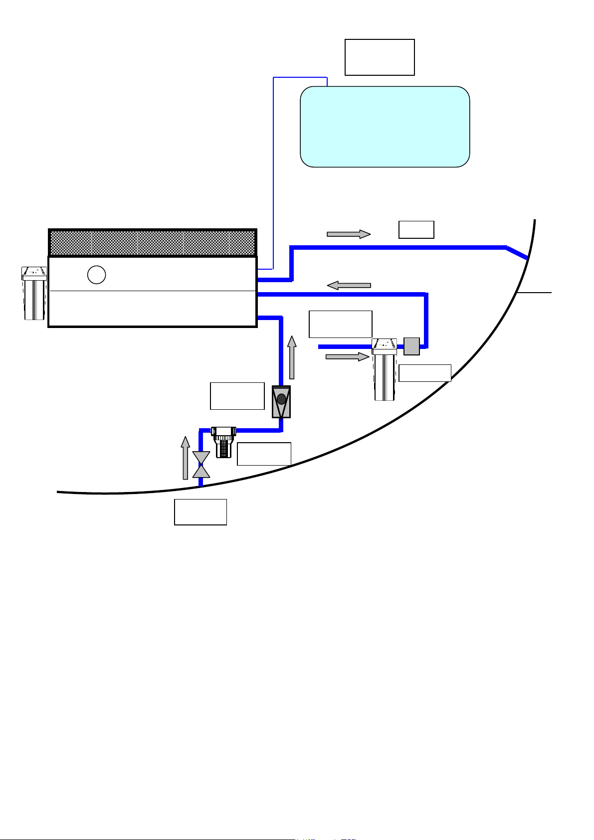
Watermaker positioning.
The horizontal and vertical distance of the watermaker, from the sea water inlet, is a critical
aspect of the installation. Even if the pumps are self-priming type, it is strictly adviced to install
the watermaker as low as possible respect the sea level, and as close as possible respect the
sea water intake.
If the watermaker is positioned too much above respect the sea level or too far from the water
inlet, the pumps will have difficult in inhaling water and frequent blocks can occur.
Usually the vertical distance respect the sea level is more critical than the horizontal distance
from the water intake. In example if the unit is positioned below the sea line, a distance from the
water inlet up to 3 meters can be tolerated.
On contrary, if the watermaker is positioned above the sea level, it is recommended a distance
from the water inlet of max 1-2 mts.
Anyway never install the unit above more than 30 cm. respect the sea level.
Avoid locating the unit where a loss of water can cause damage or jeopardize its safety.
Allow sufficient space for access to the casing containing the filter cartridge.
The unit must be installed horizontally on a suitable base strong enough to support its weight.
It may be necessary to create a suitable wooden or fiberglass structure for the unit if an existing
one not available. Avoid installing it on a surface susceptible to vibration.
The unit can be a little noisy in operation. Possible areas for siting are: sink closets, under berth
lockers, wardrobe bases (creating a false floor above it.)
Active carbons filter
The active carbons filter (and the preassembled electro-valve) need to be positioned vertically.
There are not specific restriction regarding the distance from the watermaker. The filter housing
is fixed, by means of Parker type screws, through the bracket supplied. It is necessary to leave
sufficient space below to allow unscrewing replacement of the filter.

7
2. Installation
2.3 Water intakes
The necessary hydraulic intakes are:
Seawater intake
It is ideal a specific sea water intake, size ¾” min. in a central position, well under the water
surface even when the vessel is well heeled over.
The skin fitting is recommended. It must be oriented to the bow of the boat.
As alternative it is possible Tee into an water inlet as long as the following conditions are met:
- 3/4” minimum size,
- No air can be introduced into the system from other use ie: salt water tap in galley
-Must always be under the water surface even when the vessel is well heeled over.
Allow a minimum ½” on-off ball valve on the water intake. The hose connections, especially if
under the seawater level, must be secured with double hose clamps.
It is not advisable to Tee into the engine cooling water intake as it may impair the cooling of the
engine. An easily inspected mesh type filter will be required close to the water intake. The filter
has to be of 50 microns. It is possible to use filters from existing outlets
Fresh water intake for washing.
Tee in downstream of the vessel's fresh water pressure system (Domestic water from tank) .
IMPORTANT
Flushing must always be carried out executed with the pressure water system ON.
The pressure water system must NOT exceed 2.5 BAR.
Salt-water waste (discharge)
The salt-water reject fitting must be ½” minimum and preferably above the seawater level.
Again, if required you can tee into an existing skinfitting ie: sink water out, one way valves may
need to be considered. The watermaker waste pipe must be unobstructed when the machine is in
use.

8
2. Installation
2.4 Hydraulic connections.
All of the hydraulic connections are positioned on the right side of the machine.
The specification of the connectors is the following:
Sea water inlet:
16 mm. internal diameter hose holder
Fresh water inlet for washing :
16 mm. internal diameter hose holder
Exhaust discharge:
16 mm. internal diameter hose holder
Fresh water production:
Compression fitting for 6 mm. internal /8 mm. external hose
Discharge
Sea water
inlet
Washing
fresh
water
inlet
Fresh water
production

9
Fresh water
tank
Washing
fresh water
Electovalve
Net
filter
discharge
Sea water
inlet
Non return
valve
2. Installation
2.5 Hydraulic diagram
For all the hydraulic connections (except the fresh water production pipe) use a spring type 16
mm. internal diameter hose (not furnished) and a ½”fittings. The hose must be min. PN 5 (it
must work safely with a pressure up to 5 bars).
IMPORTANT:
Sea water inlet connection.
Install the non return valve as low as possible and close to the net filter.
The hose laying must be as short and linear as possible.
Discharge connection.
Create a Swan neck upward (20 cm. above the watermaker) when the drain outlet on the vessel
is positioned below the watermaker unit, in order to guarantee a water head.
Connection to the fresh water tank (use the furnished blue 6X8 hose).
The connection has to be made using the small hose supplied with the equipment. The
connection has to be made to the upper side of the tank, on a ¼” outlet if available.
It is possible, in case of metal tanks, to make a ¼” threaded hole to connect the supplied male
connector. Another option is to Tee into the tank air vent hose.This is only possible if the
breather pipe section is more than 16 mm. dia. There are no particular limits on the connection
length.

10
2.Installation
2.6 Electric connections
The electric connections must be done between the electric box of the watermaker and the small
box connected to the computer. The power supply, coming from the service batteries, needs to be
connected to the terminals – and + of the computer box (see the table below for the
recommended section). The connection to the vessel's control panel needs to be downstream the
voltmeter and the ammeter. The connecting terminal must be suitable to support electric load
(approx. 250 Watt). A 32 A automatic circuit breaker (for 12VDC systems) must be installed on
the power supply , and 16 A (for 24VDC systems).
Electric cable: red/black single-pole cable, flame-retardant type sea wiring. The cable must be
of sufficient thickness to avoid voltage drop.
Voltage Automatic Cable lenght
switch up to 3 mts 3 - 7 mt. 7-10 mt.
Volt Ampere mm2 AVG mm2 AVG mm2 AVG
12 32 10 7 16 5 25 3
24 16 4 11 4 11 6 9
Main power supply cables and switches selection table.
Remote control panel mounting
The remote control panel has the following dimensions:
width 12 cm height 8 cm.
It can be flush mounted on any surface, providing the area behind is free of moisture and
condensation and there is enough depth to house the rear part of the panel (approx. 8 cm.).
Avoid laying the computer cable in areas where it will be submerged in water.
To flush mount the control panel a hole with the following dimensions will be required:
width 9 cm height 5 cm.
The remote panel is connected with the computer throw the pre wired black cable supplied.

11
Electric connections
Clamp connection section
+ watermaker box - computer 2,5 mm2
5 watermaker box - computer 2,5 mm2
13 watermaker box – computer box min 10 mm2
- watermaker box – computer box min 10 mm2
12 watermaker box – computer box min 10 mm2
- watermaker box – computer box min 10 mm2
- battery- computer box see table
+ battery- computer box see table
- computer box – electro valve 2,5 mm2
10 computer box – electro valve 2,5 mm2
Automatic circuit
breaker
Washing
electro-valve

12
3. Operation
selection
switches
illuminated
control
push-buttons
3.1 By-pass activation
The by-pass is activated by turning the switch located on the computer box clockwise. When the
by-pass is activated, all the electronic functions (diagnostic, automatic washing, etc.) are
disabled, and the unit works in manual mode (the pumps 1 and 2 are activated acting directly on
the PUMP1 and PUMP2 selectors). It is not possible to perform fresh water washing with by-
pass activated. By-pass activation is signaled by the continuous green light of the start push-
button.
The operation with the by-pass is necessary only in the following two circumstances:
Plant first start-up or plant restart after maintenance operations. The use of the bypass is
required at start up when purging air from the system. Without this in operation the computer
would sense that there was deviation from normal operation tolerances and would continually
shut the unit down.
Electronic failure
In the case of electronic control system failure, the by-pass allows use of the plant manually by
selecting pump 1 and pump 2 switches manually. It will however not allow fresh water flushing
of the unit as the Electro valve is controlled by the computer.
IMPORTANT
Do not engage the by-pass without good reason, as all diagnostic and automatic functions are
disabled when the by-pass is activated.
PUMP 1 PUMP 2 AUT. WASHING
START STOP MAN. WASHING
ALLA

13
3. Operation
3.2. First start-up procedure
The first start-up procedure should be followed when starting a new plant for the first time or
when restarting after laying up.
Preliminary checks:
Check that the reset valve is closed (lever orthogonal to the body valve) and the positioner
unscrewed.
Check that 5 micron filter cartridge is installed in the cartridge holder, and screwed on
tightly.
Check that the seacock and the waste water drain valves are open.
Check that the valve on the active carbon filter is opened.
Check that the vessel's pressure water pump is on.
Check that the vessel's fresh water tanks have enough water in them to perform the first
washing operation.
Start-up procedure:
1. Open the depressurization valve at approx. 45° (halfway).
2. Push for 20- 30 sec the red push-button located on the CA filter in order to purge the air from
the filter.
3. Leave both selectors PUMP1 PUMP2 and AUT WASHING not selected (vertical lever).
4. Push the push button MAN WASH. Now the electrovalve opens, filling with fresh water the
water inlet hose. After 20 seconds the red light STOP will flash. Recognize this alarm
pushing the push button STOP. Repeat this step again.
5. Connect the by-pass, by turning the switch clockwise (the START push-button green pilot
light comes on).
6. Start the first pump acting on the PUMP1 selector. After approx. 2 minutes start PUMP 2
and turn off PUMP 1. Leave PUMP 2 on for approx. 2 minutes and then start again also
PUMP 1, for further 2-3 minutes. Turn both pumps off.
7. Disconnect the by-pass by turning the selector anticlockwise (the START push-button green
pilot light turns off).Close the depressurization valve (vertical position of the blue lever).
8. Activate AUT WASHING and both pumps, and then push START. The system starts going
under pressure and the fresh water production begins.
9. Verify that there are no water leaks in the hose connections. In such case, fasten the hose clamps
further. Stop the system pushing STOP. The machine will not stop immediately, but will
perform before an automatic washing.
Warning: the electronic computer is equipped with a minimum voltage block calibrated at about
10,8 volt (12 VDC systems) and at 21,8 volt (24 VDC systems).
This protection is necessary to avoid potential battery damage and interference with the
functioning of other equipment ie: Navigation aids.
When starting the watermaker there is a short surge of power greater than the normal
consumption of the unit. If the vessel's batteries are low the computer may shut down the unit
disabling the unit under electronic control.
This can be confirmed by looking at the LED on computer, inside the Computer Box. In normal
conditions this LED is green. If the shutdown is due to insufficient voltage, the LED turns red for
a few seconds. In this case check the battery voltage.
In this case (low voltage) the watermaker can also be switched on, in manual mode, by turning
on the by-pass, or in electronic mode by starting one pump at a time (turn selector PUMP 1,
press START, after few minutes turn selector PUMP 2).

14
3. Operation
3.3. Normal operation procedure
1. Check that the seacock and waste water drain valve are opened.
2. Check that the depressurization and reset valves are closed and that the by-pass is not
connected.
3. Check that the Pressure Water system is turned on.
Fresh water production cycle without automatic washing
The automatic washing procedure uses 7 to 8 litres of water. If the unit is in use daily it is not
necessary to carry out this procedure every time water is produced. As long as the watermaker
membrane is cleaned once a week whilst in daily use, no long term damage will be done to the
watermaker.
1.Preset the pumps by turning the PUMP1 and PUMP2 switches clockwise (An approx. 30
lit/hour water production is achieved by activating one pump with a 100 Watts consumption,
while an approx. 60 lit/hour water production is achieved by activating 2 pumps with a 240
Watts consumption).
2.Do not turn on the automatic washing switch. Check that the AUT WASHING switch is in
vertical position.
3.Push the START button (the START push-button pilot light come on and water production
will begin).
4. Push the STOP button at the end of the production cycle. Do not turn the pumps off with the
pump switches as the shutdown operation will not be done electronically. There is a chance
that if turned off with the mechanism in a central position, the machine will become blocked and
need resetting manually. After pressing the Stop button the unit will not turn off immediately,
but after few seconds. This is quite normal as the computer repositions the mechanism in the
correct position before deactivating the pumps).
If during production the computer detects an anomaly (cycling missing, low
pressure, etc.) the watermaker will automatically shutdown 20 sec. after having
noted the anomaly and the STOP push-button pilot light will blink. It is
necessary to push the STOP button to restart the unit to confirm to the computer
that the failure has been recognized). Before restarting the watermaker, it is
necessary to check the reason for the failure and remove its causes.

15
Fresh water production with automatic washing
(
For use when the watermaker is not used on a daily basis or when automatic washing is
required after every water making session.)
1. Preset the pumps by turning the PUMP1 and PUMP2 switches clockwise.
2. Preset the automatic washing by turning the AUT. WASHING switch clockwise.
3. Push the START button to start the plant (the START push-button pilot light come on and
the production will begin).
4. Push the STOP button at the end of the production cycle. The plant will not turn off
immediately, but a washing cycle will be automatically activated lasting approx 50sec.
During the cycle the MAN WASHING push-button pilot yellow light will also light up. The
watermaker will automatically shutdown after the washing cycle has finished.
The fresh water consumption during an automatic washing operation is approx. 7 to 8 litres
Manual washing cycle
(If the unit is to be left unused for 2-3 months)
This operation is not intended for fresh water production, but serves to perform a deeper rinsing
of the watermaker, prior to long periods of inactivity.
Before starting the manual washing, ensure that there is a sufficient quantity of fresh water inside
the vessel's water tank. Fresh water consumption during this washing cycle is approx. 10
litre/min.
1. Turn on the pressure water system.
2. Preset the pumps by turning the PUMP1 and PUMP2 switches clockwise.
3. Do not preset the automatic washing. Check that the AUT. WASHING switch is in the
vertical position.
4. Push the MAN WASHING button to start the washing cycle (the START and MAN
WASHING button pilot lights will turn on).
5. Push the STOP button to stop the washing cycle.
Do not let this procedure continue for more than 10 minutes as this is more than sufficient to
remove any build up of salt in the watermaker, It will also very quickly empty your water tank.

16
ATTENTION
If the watermaker has been stopped by using the pump switches and not the Stop button, or if
some air is in the system, the automatic hydraulic valve may stop in a central position. This
means that pressure on both sides of the valve are the same and the unit is effectively stalled and
has to be manually restarted.
The symptoms of this are when the pumps are turned on, the manometer reaches an elevated
pressure ( more than 9 Bar) and the pumps shutdown automatically by the pressure switches
intervention. The pumps then have the tendency to try to restart when the pressure decreases, and
then to jam again, resulting in a typical start-stop noise. After approx. 20 sec. the computer
senses the anomaly, and turns the pumps (the red light flashes).
Recognize the alarm activating the STOP push-button.
This phenomenon, besides being very rare, does no harm to the system, but it is necessary to
reset the valve with the following simple procedure:
RESET PROCEDURE
1. Turn the system off.
2. Open the reset valve (lever in horizontal position).
3. Screw the positioner knob clockwise until it can be moved no further. 10 turns at
least are necessary.
4. Unscrew the positioner knob up to the original position, until when it is blocked
back.
5. Close the reset valve (lever in vertical position).
6. Restart the system

17
4. Maintenance
4.1 Shutdown procedure
It is necessary to perform the shutdown procedure before effecting standstills longer than 3
months, for instance before laying up for winter.
The purpose of the shutdown is to clean the unit of possible deposits of limestone, and to inhibit
the growth of microorganisms that may reduce the reverse osmosis membrane's efficiency.
The following equipment is necessary in order to perform the shutdown operation:
1 ea. recipient 20 liters minimum capacity (a bucket of such capacity could also be suitable).
Two 16 mm. linen hoses of a length that allow them to be fed into the same container
A prepared shutdown solution SCHENKER CLEANING 1.
Tools for de-assembling hoses (screwdrivers, pliers, etc.)
The shutdown procedure is:
1. Replace both active carbon filter and 5 microns cartridges.
2. Collect approx. 15 liters of unchlorinated fresh water into the bucket. The water
produced by the watermaker itself could be fine.
3. Empty the entire content of the SCHENKER CLEANING 1 solution into the picked
water, and mix carefully following the indications on the pack. Wear a protection mask
in order to avoid inhaling product dusts. The water temperature doesn't have to be lower
than 25°C preferably. Disconnect the watermaker’s sea water inlet hose and discharge
hose.
4. Insert the end side of the 2 hoses into the bucket, verifying that the hoses have been
properly dipped in the solution and that they don't inhale air.
5. Open the depressurization valve at 45°.
6. Start the watermaker (with both pumps, and bypass activated ) and leave the system on
for approx. 30-40 min., checking that the hoses are properly positioned in the container,
so as to avoid drawing air or spilling the liquid into the boat.
7. Turn the watermaker off, and re-connect the hoses, without drain out the solution.
When the unit is restarted open the depressurization valve at 45° for about 10 minutes in order to
completely drain out the chemical solution.
Chemical Cleaning Kits:
Schenker No 1 is an acid based organic cleaner.
This is used for 'pickling' the watermaker when not in use and as part of the general cleaning
process. See 4.1 Shutdown procedure
Schenker No 2 is an alkaline base organic cleaner. If the watermaker has been left standing
without pickling or has a 'bag egg” smell, cleaning with Schenker No2 will remove this.

18
4. Maintenance
4.2 Verifications and periodic maintenance
The following periodic procedures are to be followed to maintain trouble free operation:
Purge the air periodically.
During the function sometime air can be collected in the unit. Periodically (i.e. every 10 days)
purge the air opening, during the normal functiuoning, the depressurization valve for 20-30
seconds.
Check the filter
It is necessary to replace the filter if it is particularly dirty. The changing interval depends on the
number of daily working hours of the watermaker, and on the cleanliness of the seawater where
it is used.
It is necessary to replace the filter every 15-20 days under normal conditions (4 hours/day
usage).
It is necessary to purge air from the housing once the filter has been cleaned or replaced. Leave
the watermaker on for 2-3 minutes with the depressurization valve opened at 45° to perform the
purging.
Check the plant working pressure
Check the pressure on the manometer located on the front panel.
The working pressure depends on many factors such as water temperature, salinity level of
seawater, battery voltage, cleanliness of membranes and type of installation.
The pressure, under mid range working conditions is approx. 5,6 BAR with one pump on, and
approx. 7,6 BAR with two pumps on. There is a small pressure loss , in the range of 0,2 Bars,
during the cycle.
If the average pressure exceeds the above range it is necessary to check:
1. Check for obstructions in the suction or drainage hoses (ie: kinks in the hose).
2. The battery voltage.
3. The cleanliness of the membranes. If the membranes are dirty it will be necessary to perform
the shutdown procedure 4.1. If there in little improvement in may be necessary to perform an
alkaline wash using the chemical product SCHENKER CLEANING 2.
4. The seawater temperature. If the temperature is lower than 18°C (winter temperature) the
pumps pressure can, exceed 8 Bar. In this instance could be necessary increase slightly the
working pressure of the pressure switch to bring the pressure back to 7,8-8 Bar.(1.3 System
description)
Check for absence of leaks
It is necessary check this at plant start-up, since possible leaks due to accidental causes (pipe
bursting, hose clamp loosening, equipment failure, etc.) may cause leaks, and endanger the
vessel.
Membrane replacement
The reverse osmosis membranes have an average working life of 5-6 years. After 5 years they
usually may start to degrade. If in doubt as to their condition contact a Schenker service point
and replace as a matter of course after 7 years.

19
4. MAINTENANCE
4.3 SYSTEM TROUBLESHOOTING
PROBLEM PROBABLE CAUSE SOLUTION
Pumps do not start Pumps pressure switch burned
Electronic failure
Replace
Activate the by-pass
Pumps start but stop at
high pressure System is blocked
Dirty filter
Dirty membranes
Trouble in the cycling system
Perform Reset procedure
and purge the unit
Replace cartridge
Perform cleaning cycle
Contact a Schenker service
point
While functioning the
pumps momentarily shuts
down
Dirty filter or membranes
Pump pressure switch not
calibrated
Cold sea water
Clean or replace See 4.2
Calibrate pressure switch
Low production / normal or
low pressure Low battery voltage
Air in the plant
Seal system leak
Check battery voltage
Perform bleeding See 3.2
Contact a Schenker service
point
Low production / high
pressure (> 8 Bar) Cold sea water
Dirty membranes
Normal condition
Calibrate Pressure switch
Perform cleaning cycle
4.2
Leaking in the plant Loose pipe connections
ERS loss Tighten connections
Contact a service point

20
ELECTRONIC TROUBLESHOOTING
When pressing start button the system will not start
Check that the by-pass is not switched on (bypass switch turned anticlockwise) and that at least
one pump is activated (switch PUMP1 or PUMP2 turned on).
If the system still fails to start...
Check that electric cables are properly connected, follow the wiring scheme indicated in the
manual and that the main automatic circuit breaker is in place.
If the system still fails to start...
Check with a tester, the 12/24 VDC electrics box power supply, between clamps + and - .
If the system still fails to start...
Turn off both pump 1 and pump 2 selectors (vertical position). Push START.
If the green pilot light turn on and, after 20 seconds the system shutdown (because the pumps are
not connected) the problem is due to low battery voltage.
If the system still doesn’t start check all electric wiring, electrical connections box, pre-wired
cable remote panel for fault. Replace as required.
When pressing START the system starts, but shuts down after 20 seconds.
Check for a hydraulic block. (the pressure on the manometer will be greater than 8 bar and
pumps are shut down) . In this case perform the reset procedure and restart the system. (Page 16)
If a hydraulic block has not occurred, the most probable cause of the fault is a malfunction of the
pressure switch.
The pressure switch can be tested with following procedure:
1. Disconnect the pressure switch cables (clamps 5 + ).
2. Activate the by-pass and start the system in manual mode.
3. Check with a tester in ohm position the functioning of the pressure switch. In normal
conditions the pressure switch closes and opens the circuit each 3-4 seconds.
4. If the pressure switch remains either closed or open during the functioning of the
watermaker, the switch is faulty and must be replaced.
Table of contents
Other Schenker Water Filtration System manuals

Schenker
Schenker SMART 100 User manual

Schenker
Schenker SMART 80 User manual

Schenker
Schenker MODULAR 60 User manual

Schenker
Schenker 50Z12/24B Service manual

Schenker
Schenker ZEN 150 User manual

Schenker
Schenker SMART 30 User manual

Schenker
Schenker MODULAR 35 User manual

Schenker
Schenker ZEN 30 User manual

Schenker
Schenker SMART 60 User manual

Schenker
Schenker ZEN 50 Service manual