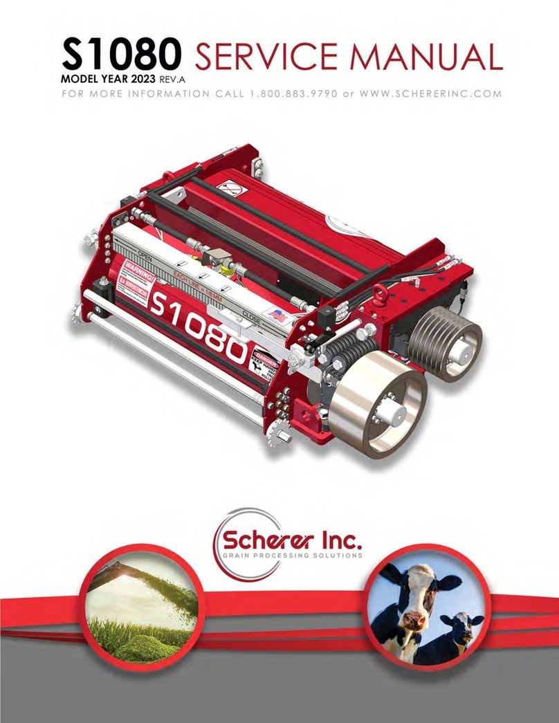
Scherer 1085SI User manual


Index
1
2
4
6
9
11
13
15
16
17
18
19
20
25
26
27
32
33
34
35
37
38
39
41
43
44
45
46
47
48
49
50
51
52
53
54
55
56
Section Page #
Contact Page
Service New Product Warranty
Safety
Stone Door Cyl. Retrofit 498 & Newer
Stone Door Cyl. Retrofit 494-497
498 & Newer Schermist® Installation
494 - 497 Schermist® Installation
Schermist® Upgrade Kit
Schermist® Operation
Scherer Grease KP Installation
Kernel Processor Installation
Taper Lock Installation
Sentry 2.0 Installation
Scherer Sentry 2.0 Parts
Scherer Sentry 2.0 Grease Parts
Air Dryer Installation 498 & Newer
Belt Options
7 Groove Pulley Options
Roll Gap Adjustment Instructions
Maintenance Intervals
Roll Change Instructions
Processor Opening Instructions
End of Year Roll Maintenance
Roll Bearing Removal & Installation
Schermist® Head Rebuild
Important Torque Specifications
Top Frame Parts
Top Frame Parts List
Top Frame Adjustment Parts
1085si Adjustment Options
Bottom Frame Parts
Bottom Frame Parts List
Slide Parts
Temperature Wiring Parts
Air Lubrication System Parts
Grease & Oil Lubrication Kit
Complete Roll Options
No Housing Roll Options
Secon Page #
Roll Parts
Roll Housing Parts
Bulb Seal Replacement Kit
Cheek Plate Replacement Kit
Schermist® Parts List
Schermist® Head Parts List
Grease/Manual Lubrication Parts
Manual Lubrication Parts
Latch Block Parts
Decal Layout
Scherer Equipped
Accessory Parts
57
58
59
60
61
66
67
68
69
70
71
72

1
U.S. Patent No. 7,681,384
Others Patents Applied for
Foreign Patents Applied for
46994 Mindy St. Tea, SD 57064
1-800-883-9790
(605) 368-2659
Fax: (605) 368-9737

2
LIMITED WARRANTY ON NEW SCHERER KERNEL PROCESSORS AND PROCESSOR ROLLS
Scherer, Inc. (“Scherer”) will provide for repairs or replacement, at its option during the warranty
period of each new Scherer Kernel Processors and/or new Scherer Kernel Processor Rolls in
accordance with the following terms, conditions, and limitations.
WHAT IS COVERED
WARRANTY APPLIES –This warranty is for new Scherer Kernel Processors and/or new Scherer
Kernel Processor Rolls installed in a Claas® Forage Harvester by a certified technician, and is
provided to the original and any subsequent owner(s) of the Claas® Forage Harvester during the
warranty provision.
REPAIRS COVERED –The warranty covers repairs or replacement, at Scherer’s option, to correct
any malfunction resulting from defects in the design, material or workmanship occurring during
the warranty period. Needed repairs or replacements will be performed using the method
Scherer determines most appropriate under the circumstances.
OBTAINING REPAIRS –To obtain warranty repairs, contact Scherer at portal.schererinc.com.
WARRANTY PERIOD –The warranty period for all coverages shall begin on the date installed by
the dealer and shall continue for twelve months.
WHAT IS NOT COVERED
DAMAGE DUE TO ACCIDENT, MISUSE, or ALTERATION –Defects and damage caused as a result
of any of the following are not covered:
Flood, Collision, Fire, Theft, Vandalism, Riot, Explosion, Acts of Terrorism;
· Misuse of the Forage Harvester;
· Installation into unapproved applications and installations;
· Alterations or modification of the Kernel Processor, Processor Rolls, or Forage Harvester;
· Anything other than defects in the Scherer Kernel Processor or Processor Roll design,
materials, or workmanship.
DAMAGE CAUSED by LACK of MAINTENANCE –Defects and damage caused by the owner’s
failure to follow the recommendations of the maintenance schedule provided by Scherer.
MAINTENANCE –Normal Maintenance (such as adjustments after initial installation and use as set
out in the owner’s manual; periodic maintenance as set out in the owner’s manual based upon
hours of use, and END OF SEASON maintenance as set out in the owner’s manual) is not covered
and is the owner’s responsibility.
USE OF OTHER THAN GENUINE SCHERER PARTS –Defects and damage caused by the use of parts
that are not genuine Scherer parts are not covered.
EXTRA EXPENSES – Economic loss and extra expenses are not covered. Examples include but are not limited to: loss
of Forage Harvester use, inconvenience, lost prots, loss of me, any travel costs.
Service New Product Warranty

3
OTHER TERMS APPLICABLE TO CONSUMERS AS DEFINED BY THE MAGNUSON -MOSS WARRANTY
ACT
This warranty gives you specific legal rights and you may also have other rights which vary from
state to state.
Scherer Inc. does not authorize any person to create for it any other obligation or liability in
connection with these Kernel Processors and Processor Rolls. ANY IMPLIED WARRANTY OF
MERCHANTABILITY OR FITNESS FOR A PARTICULAR PURPOSE APPLICABLE TO THESE TRANSMISSIONS
IS LIMITED IN DURATION TO THE DURATION OF THIS WRITTEN WARRANTY. PERFORMANCE OF
REPAIRS AND NEEDED ADJUSTMENTS IS THE EXCLUSIVE REMEDY UNDER THIS WRITTEN WARRANTY
OR ANY IMPLIED WARRANTY. SCHERER INC. SHALL NOT BE LIABLE FOR INCIDENTAL OR
CONSEQUENTION DAMAGES (SUCH AS, BUT NOT LIMITED TO, LOST PROFITS OR RENTAL EXPENSES)
RESULTING FROM THE BREACH OF THIS WRITTEN WARRANTY OR ANY IMPLIED WARRANTY.**
** Some states do not allow limitations on how long an implied warranty will last or the exclusion
or limitation of incidental or consequential damages, so the above limitations or exclusions may
not apply to you.
OTHER TERMS APPLICABLE TO OTHER END-USERS
THIS WARRANTY IS THE ONLY WARRANTY APPLICABLE TO THE SCHERER KERNEL PROCESSORS AND
PROCESSOR ROLLS AND IS EXPRESSLY IN LIEU OF ANY OTHER WARRANTIES, EXPRESSED OR
IMPLIED, INCLUDING IMPLIED WARRANTY OF MERCHANTABILITY OR FITNESS FOR A PARTICULAR
PURPOSE. SCHERER INC. DOES NOT AUTHORIZE ANY PERSON TO CREATE FOR IT ANY OTHER
OBLIGATION OR LIABILITY IN CONNECTION WITH SUCH KERNEL PROCESSORS OR PROCESSOR
ROLLS. SCHERER INC. SHALL NOT BE LIABLE FOR INCIDENTAL OR CONSEQUENTIAL DAMAGES
RESULTING FROM BREACH OF THIS WARRANTY OR ANY IMPLIED WARRANTY.
Scherer Protection Extension
Eecve 11/30/21 Extend the standard 1-year Limited Warranty up to +4 years (5 years total). Scherer Protecon
Extension must be purchased at same me the KP order is placed. All Scherer Protecon Extension Warranes
need to be led on the Dealer Portal. Annual inspecon to be completed by the Dealer & led under the warranty
secon of Dealer Portal. Failure to le annual inspecon may result in rejected warranty claims. Scherer Protecon
Extension is not retroacve to any kernel processors that have already been in service. Scherer Protecon
Extension is transferrable to 2nd owner. Unlimited acres/hours/tons, No deducble. Scherer does not warranty
normal wear items, including but not limited to, Cheek plates, bulb seals, rolls, felt seals, KP belt, pulleys, or taper
hub assemblies. Scherer does not warranty normal maintenance items on KP or air system components, including
but not limited to, Filters, gaskets.
QUESTIONS
If you have any questions regarding this warranty or the performance of warranty obligations,
you may contact Scherer, Inc. thru the dealer portal: portal.schererinc.com.

4
Safety
Warning: Read and understand all of the following safety messages. Be familiar with
general operating and maintenance instructions. Be sure to lock out the power supply
before performing any maintenance and adjustments. The person performing the
maintenance should be the only one with the ignition key for the machine.
General Safety Practices,
Always observe safe operating practices around machinery. Most accidents are the
result of carelessness or negligence. All rotating machinery is potentially dangerous.
Guard and operate rotating machinery as required by applicable laws, regulations and
good standard safety practices.
Before doing any maintenance on engine driven machinery, turn off ignition.
Remember, the person doing the maintenance or adjustment should be the only one
with the ignition key.
Use the proper tools for each maintenance task. Keep lifting equipment in good
condition and DO NOT stand under objects being lifted. Keep a clean work area to
ensure workers have good footing.
Inlet/Discharge Opening Hazard
The processor has an inlet and discharge opening. Injury will result if persons or objects
fall into the inlet or discharge. A serious hazard exists if a person places their arm or any
object into the inlet or discharge area of the processor. DO NOT remove protective
guards.
Belt Drive Hazard
Be sure that the belt guards are in place before operating the processor.
Rotating Rolls Hazard
The rotating rolls are a severe hazard. The rolls turn at high speeds and operate with a
grinding action that will pull objects between the rolls. Keep all body parts and all
objects out of this area. DO NOT insert any part of your body or any tool into the roller
area.

5
Eye Protection
Wear approved safety glasses when working around all equipment. Moving machinery
can throw objects unexpectedly.
Head Protection
Wear an approved hard hat while installing the processor into and out of the machine.
Falling objects or low overhead can cause severe injury while installing or removing the
processor from the machine.
Hearing Protection
Under normal operating conditions, this machine does not produce hazardous noise.
However, the machine itself is very noisy when operated at full throttle. Wear approved
hearing protection as needed when working around equipment.

6
Stone Door Cylinder Retrofit 498 & Newer
1.) Using Kit HOD1405 : In the front of the KP service compartment, remove the clevis pin
from the sharpening door cylinder. Take the supplied template HOD1404, and line it up
with the outside of the left bracket. Align top of template making it flush with top of
mounting ear. Use two locking pliers or a c-clamp, to hold the template in place. Insert
the clevis pin through the top holes to help line it up. Use a sharpie or spray paint to
transfer the line to the bracket. Make sure to hold the template firmly in place for accu-
rate transfer of hole position. Take a ½” drill bit, and drill two holes in the bracket on the
SPFH, using the template as a guide.
HOD1408
2.) Once the left side is done, move the template to the inside of the right bracket. The
holes for the right-side bracket will need to be drilled from the left side. There is not
enough room to fit a drill in from the right. Using a cut-off wheel, cut along line and dis-
card pieces. Using the hardware provided install bracket HOD1408 and attach stone
door cylinder.
HOD1404

7
3.) When applicable, remove the foam seal around the cylinder and trim as shown to
allow for the cylinder to travel in cutout with out binding.
4.) The slotted arc on HOD1408 is there to allow for adjustment to ensure the door has
pressure on it in the closed position, and opens far enough to clear the sharpening stone
carriage.

8
HOD1405 - 498 & Newer

9
Stone Door Cylinder Retrofit 494 - 497
1.) Using Kit ASM10010 : In the front of the KP service compartment, remove the clevis pin
from the sharpening door cylinder. Take the supplied template PRT10018, and line it up
with the outside of the left bracket. Use two locking pliers or a c-clamp, to hold the tem-
plate in place. Insert the clevis pin through the top holes to help line it up. Use a sharpie
or spray paint to transfer the line to the bracket. Make sure to hold the template firmly in
place for accurate transfer of hole position. Take a ½” drill bit, and drill all four holes in
the bracket on the SPFH, using the template as a guide.
PRT10018
2.) Once the left side is done, move the template to the inside of the right bracket. The
holes for the right-side bracket will need to be drilled from the left side. There is not
enough room to fit a drill in from the right. Using a cut-off wheel, cut along line. Using the
hardware provided, install the cut off ears to the attached parts still attached to the
SPFH.

10
ASM10010 - 492 To 497

11
Locate 90° fitting under the left-hand hood (Image 1). Remove the 90° fitting, and re-
place it with the “T” fitting (SPL10111). Take the 90° fitting that was removed and install it
on the open end of the “T”. Install the adapter fitting (HPD1423), the union (HPD1422),
and then the push-lock fitting (OM1025). See image 2 for this process. From there run a
short piece of supplied plastic airline (D1348) and install the ¼ turn valve (HPD1359). This is
seen in image 3.
Image 1 Image 2
Image 3
498 & Newer Schermist®Installation

12
Remove the service panel, in the KP compartment. Drill a hole and mount the threaded
bulkhead fitting (HPD1425) as shown (Image 1). Install the 90° fitting (HPD1420) on both
sides of the bulkhead fitting. Take the supplied air-line and route it from the 1/4 turn valve
to the 90° fitting on the back side of the bulkhead. (Image 2) NOTE: If the machine has
diff lock you can install the bulkhead back 2” to clear the added air-line.
With the service panel off, drill and
mount the Schermist® and
coalescing filter assembly. Bolt the
service panel back onto the
machine. Run a small piece of air-
line (D1348) from the 90° fitting on
the bulkhead to the coalescing
filter. Run another section of line
from the filter to the Schermist®
assembly (Image 3).
Image 1 Image 2
Image 3

13
494 - 497 Schermist®Installation
Connect supply hose to the CLAAS air hose as shown above, using provided “T” fitting
(HPD1349). You will have to cut ¾” out of the CLAAS hose in order to install “T” fitting.
Route supply hose up and between cab and chute using provided wire-ties in order to
connect to the coalescing filter .

14
Remove the service panel, in the KP compartment. Drill a hole and mount the threaded
bulkhead fitting (HPD1425) as shown (Image 1). Install the 90° fitting (HPD1420) on both
sides of the bulkhead fitting. Take the supplied air-line and route it from the 1/4 turn valve
to the 90° fitting on the back side of the bulkhead. (Image 2) NOTE: If the machine has
diff lock you can install the bulkhead back 2” to clear the added air-line.
With the service panel off, drill and
mount the Schermist® and
coalescing filter assembly. Bolt the
service panel back onto the
machine. Run a small piece of air-
line (D1348) from the 90° fitting on
the bulkhead to the coalescing
filter. Run another section of line
from the filter to the Schermist®
assembly (Image 3).
Image 1 Image 2
Image 3

15
Converting Standard Oiler to Metric Oiler
ASM10378
ASM10378 is only needed when upgrading a KP to a newer model that utilizes metric
fittings. When upgrading from a HDS, HP, HPM-60, or HO to a S series KP this upgrade kit is
needed.

16
Schermist®Operation
• Make sure to maintain an air pressure of 35psi at the Schermist® regulator.
• Oil fill is the plug located on the front of the Schermist® reservoir.
• The air and oil screws on top of the Schermist® head are preset at the factory. To
maintain ideal operating conditions DO NOT ADJUST THESE SCREWS.
• Fill with oil until the oil level matches the full mark on the sight glass. SCHERMIST®
WILL NOT FUNCTION PROPERLY IF IT IS FILLED ABOVE THE FULL MARK!!
• Only use Scherer KP oil. It is available from dealer in 1 gallon, and 5 gallon quantities.
• In very wet corn conditions, we recommend changing the oil in the bearings every
two weeks and at the end of the season. To change the oil, remove the most con-
venient plug and drain. Refill the bearing housing with .50 oz. of fresh oil.
• At the end of season, remove all water from regulator and air lines to prevent dam-
age from freezing.
• When removing the kernel processor, disconnect the hose from the Schermist® ex-
haust port and plug the end of the hose to keep dirt out. Also cap off the Schermist®
exhaust port and turn off the air supply to the Schermist® .
• THE SCHERMIST® SYSTEM SHOULD NOT BE PRESSURIZED IF THE EXHAUST
PORT IS CAPPED OFF.

17
Scherer Grease KP Installation
When installing a Scherer grease KP, the lubrication line attached to the KP
(ASM10179—seen on page 67) can be hooked up directly to the forage
harvesters greaser. The line on the KP connects to the factory grease KP
hook up. This can be seen in the images below.

18
1.) Before lifting the processor into place in the machine, ensure that the latch blocks and
hinges are tight. Never stand under the processor when it is lifted overhead.
2.) You can install the processor from the side or from the top. For ease of installation, remove
the crossbar support that is bolted to the floor and to the discharge chute. Place processor in
the machine. If you have removed the crossbar support, install it back into place at this time.
3.) Slide the processor in the operating position, using the same clamping system that is in
place for the original processor. Ensure the latch blocks on the processor are tight.
Kernel Processor Installation
4.) Check fitment of processor in relationship to the top edge of the transition chute wear liner
(red circle - image above) both sides. Grind edges if necessary to allow processor to slide into
position. Check clearance when transition chute is in operating position. Carriage bolts from
the bottom of the accelerator can be turned around to create more clearance. Make sure
the rolls spin free when the engine is running, and belt is off.
5.) Check clearance for processor ledge to slide under bolt head on both sides (red arrows -
image above). Grind bottom of the head of the socket head cap screw if necessary. Also be
aware of the two different hole positions. This needs to line up the grass chute. The Scherer KP
also has an adaptor on the KP frame to help with this.
6.) With the processor ahead and secured into the operating position, you now need to check
proper pulley alignment. Do this by laying a straight edge along the main drive pulley and
along the processor pulleys. A laser alignment tool (A0011) can be purchased to insure precise
alignment. This needs to be done on all installations, new and used KP’s. If any adjustment
needs to be done, please refer to keyless taper lock torque specifications in the back of this
manual.
Table of contents
Other Scherer Farm Equipment manuals
Popular Farm Equipment manuals by other brands

Westfield
Westfield MKX130 Series Assembly & operation

CONVEY-ALL
CONVEY-ALL 1214-GN Operator's manual

Ventrac
Ventrac Terra Rake KR502 Operator's manual & parts drawings

Raven
Raven RS1 Calibration and Operation Manual

Krone
Krone AM 203 CV operating instructions

Raven
Raven SmarTrax Supplement Installation Manual