Schlage ENGAGE GWE Wiring diagram
*P517-057*
P517-057
ENGAGE™ Gateway
Installation Instructions
User Guide
Model GWE
For the latest Installation Instructions and User Guide for the ENGAGETM Gateway and all
other ENGAGE enabled devices, visit:
Para obtener las últimas Instrucciones de Instalación y la Guía del Usuario para la
Gateway ENGAGE y otros dispositivos provistos por ENGAGE, visite el sitio:
Pour les instructions d’installation et le manuel de l’utilisateur les plus récents pour la
Gateway d’ENGAGE et tous les autres dispositifs actionnés par ENGAGE, rendez-vous
à l’adresse :
Para español, pág. 21.
Pour français, voir la page 41.
us.allegion.com/gateway
2
General Architecture
The ENGAGE Gateway can work in two modes.
1. RSI Mode
In this mode, the Gateway communicates with
an access control panel (ACP) and alliance
partner access control software to control the
system. Power is supplied by the ACP power
connector (12 or 24V) or the included wall
power supply. Data is supplied by either a 2-
or 4-wire RS-485 connection from the ACP.
2. IP Mode
In this mode the Gateway communicates
to an access control server over IP using
an ethernet cable. The Gateway must be
recommissioned to switch between the
following modes of IP operation:
• Client mode: the Gateway and access
control server reside within the same
network.
• Host mode: the access control server resides
outside of Gateway’s local network. The
Gateway will communicate to the access
control server via websockets. The access
control server must have websockets
congured before the Gateway is able to
connect.
Power Status
Power status is indicated by the status LED
located on the front of the ENGAGE Gateway.
To see the power status LED location, refer to the
LED Indicator Guide on page 13.
Communication Status
When the Gateway is congured to communicate
with an RS-485 access control panel, the transmit
and receive status is indicated with two LEDs,
located on either side of the RS-485 connector.
When the Gateway is congured to communicate
with an IP-based host over ethernet, the status of
the LAN link is indicated on the ethernet port of the
Gateway.
Customer Service
1-877-671-7011 www.allegion.com/us
Table of Contents
General Architecture 2
Power Status
Communication Status
Port Guide 3
Installation Instructions 4
Overview
Create a new ENGAGE account
Install and commission locks
Determine the Gateway location
Wi-Fi access point placement
Commissioning and Linking 5
Commission the Gateway
Host/Panel communication with Gateway
Linking locks/devices to Gateway
Mounting Options 6
Power Options 8
Access Control Panel Connections 9
Typical Gateway to ACP wiring diagrams 10
Cable/Wire Specications 12
Factory Default Reset (FDR) 12
LED Indicator Guide 13
Troubleshooting 14
FCC Statement 17
3
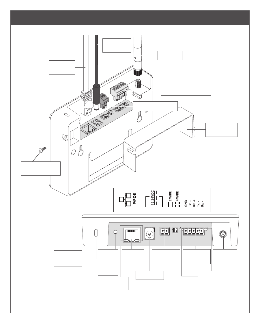
Port Guide
Antenna
RS-485 connector
Power connector
Wire guard
cover
24V DC
power cord
Ethernet
cable
Security screw
(optional)
Top View
Kensington
lock slot
Factory
Default
Reset
button
PoE/
Ethernet
Port
Power port RS-485
LEDs
IP
LEDs
ACP DC
power
input
RS-485
Port
Antenna
*not supplied
4
Installation Instructions
Overview
1. Create an ENGAGE account and site within
that account. Identify access control software
you will be using at that site (see below).
2. Install and commission locks/devices with
the ENGAGE mobile application. Make sure
the locks/devices are commissioned into the
appropriate site.
3. Commission the Gateway and link devices to
begin the Gateway install setup.
LNote, the Gateway should not be mounted
yet. This step is to determine if the Gateway
location will give a reliable connection
to linked devices before mounting (see
Determine the Gateway location on page 4).
4. After determining the proper gateway location,
mount and select a Gateway power option (pg.
7) and wire the Gateway to the host or ACP.
See Mounting Options on page 7 and Typical
Gateway to ACP wiring diagrams on page 11.
5. Conrm that the Gateway is communicating
with the access control host or access control
panel. See Host/Panel Communication with
Gateway on page 5.
Create a new ENGAGE account
An account is required to use the ENGAGE cloud
based web and mobile tools. If you do not have
an account, create an ENGAGE account with the
ENGAGE mobile or web application. The web app
can be accessed at
http://portal.allegionengage.com.
The mobile application is available on the App
Store (iOS) or on Google Play (Android). Search
for “Allegion ENGAGE.” Email access will be
needed to validate account.
Create a site within that account and choose the
software provider you will be using from the list.
(ENGAGE should only be selected if you are using
the ENGAGE manged standalone solution without
a Gateway.)
NOTE
Before creating the site, be sure to align with
your access control software provider on their
preference to manage the site. The software
provider may want to create the site and invite you
to manage.
If you have access to multiple sites, you will be
prompted to select the site you want to work with
when you log into your ENGAGE account.
Install and commission locks
Refer to the installation instructions and user guide
that came with the devices/locks. Documentation
for all ENGAGE enabled devices can be found at
www.allegionengage.com.
Determine the Gateway location
Perform a site survey to ensure reliable wireless
communications between the Gateway and the
edge device.
LNote: You will need power to the Gateway to
conduct a site survey. See us.allegion.com/
gateway for details on how to conduct a site
survey.
The Gateway communicates wirelessly using
Bluetooth to ENGAGE enabled devices/locks.
Wireless signals are diminished by walls, distance,
metal objects, or barriers. Consider the following
when placing the Gateway:
• The performance of wireless connectivity is
highly dependent on the physical (geometry,
construction materials, and furnishings) and RF
environments of the install. In typical building
environments, up to 30’ line of sight to the door
can be achieved with the 2.4GHz Bluetooth low
energy.
• Do not mount the locks/devices and the
Gateway on dierent oors. The signal will be
degraded and functionality can be severely
limited.
• Do not mount the Gateway on a metal surface.
A separation of at least one inch must be
maintained in all directions from any metal.
• Signal will not pass through metal walls or
metal mesh in the walls (stucco).
• The Gateway antenna should be vertically
oriented.
When planning, keep in mind that items can create
interference that may reduce range. Items such
as: Wi-Fi access points, metal furniture (shelving
and cabinets), HVAC equipment, elevators, cellular
repeaters, and microwave ovens all can cause
interference.
Do not install the gateway in a metal box or on a
5
metal surface. Do not install the Gateway outdoors.
2.4 GHz Wi-Fi access points
To minimize RF interference from Wi-Fi access
points, maximize the distance between the
Gateway and the Wi-Fi access point (at least 10’).
Locations and wiring methods shall be in
accordance with the National Electrical Code,
ANSI/NFPA 70 for U.S. and Canadian Electrical
Code for Canada.
For more details on Gateway placement see
us.allegion.com/gateway.
2.4 GHz Wi-Fi environments
The 2.4GHz frequency band is utilized by a
growing number of products. The Gateway-to-
device BLE communications require an open
channel in the 2.4GHz band to transmit. If the local
2.4 GHz Wi-Fi router is not properly congured
the Gateway/device’s BLE communications can
be hindered, preventing the system from working
properly.
To properly congure a 2.4 GHz Wi-Fi router to
work with the Gateway and ENGAGE device,
set the router to operate on channels 1, 6, or
11. Multiple routers within the same local area
should each be set to Wi-Fi channels 1, 6, or 11.
Wi-Fi routers that are congured to operate on
other channels (or set to “Auto Conguration”)
can interfere with Gateway operation. Consult the
product documentation for the Wi-Fi router to set
up the correct channel, or consult with a wireless
expert to aid on-site planning and setup.
For more details on managing frequency bands
see us.allegion.com/gateway.
Commissioning and Linking
Commission the Gateway
1. Power the Gateway.
The Gateway will go through a power on self-
test. When the light on the Gateway turns solid
red, it is ready to be commissioned.
2. Make sure you are working in the correct site in
the mobile app.
3. Select the ENGAGE Gateway.
4. Follow the commissioning wizard. You will need
to dene how the Gateway will be used: IP
or RSI. Consult your access control software
provider for details.
Host/Panel communication with
Gateway
The Gateway supports RSI and IP data
connections.
IP Mode
To use the Gateway with an IP connection, use an
ethernet connection for data. Consult the software
alliance partner to congure the Gateway. IP
communication will depend on installation site and
network topology.
RSI Mode
Connect ACP to the Gateway using either 2- or
4-wire RS-485 connections. Consult the software
alliance provider on Gateway congurations.
The Gateway has RS-485 communication status:
two LED indicators located near the RS-485
port. The green LED will ash when the Gateway
detects RS-485 trac. The red LED will ash when
the Gateway is transmitting data back to the ACP.
See your access control software documentation
for more information.
Linking locks/devices to Gateway
The linking process for an ENGAGE Gateway and
ENGAGE enabled devices may require remote
linking. Align with the software partner for the
preferred method. The steps to link will depend on
the host conguration of the Gateway. See below
for either IP mode or RSI mode link instructions:
1. Conrm that both the Gateway and locks/
devices are commissioned into the same site.
2. Using the mobile app in the appropriate site,
click on the specic Gateway you want to link to.
3. Select “Linked Devices.”
4. Click the “+.”
RSI only:
5. Assign the door number.
6. Put lock/device into linking mode (see “Device
linking mode” on page 6).
IP Only:
7. Select the lock/device to be linked.
Table of contents
Languages:
Other Schlage Gateway manuals


