schmalenberger fluvo C2G rondo User manual

C2G rondo
D
GB
27201 - H
Operating Instructions
Transplantation of the original

Contents
5 0 C2G rondo
Version: 27201 - H
Schmalenberger GmbH + Co. KG
D-72072 Tübingen / Germany
Contents
1 General............................................................................................... 5
1.1 Guarantee notice ............................................................................................................. 5
1.2 General............................................................................................................................ 5
1.3 Usage Instructions........................................................................................................... 5
2 Safety Instructions............................................................................ 5
2.1 General............................................................................................................................ 5
2.2 Symbols........................................................................................................................... 6
3 Unit Description / General Technical Data...................................... 6
3.1 Technical Data................................................................................................................. 6
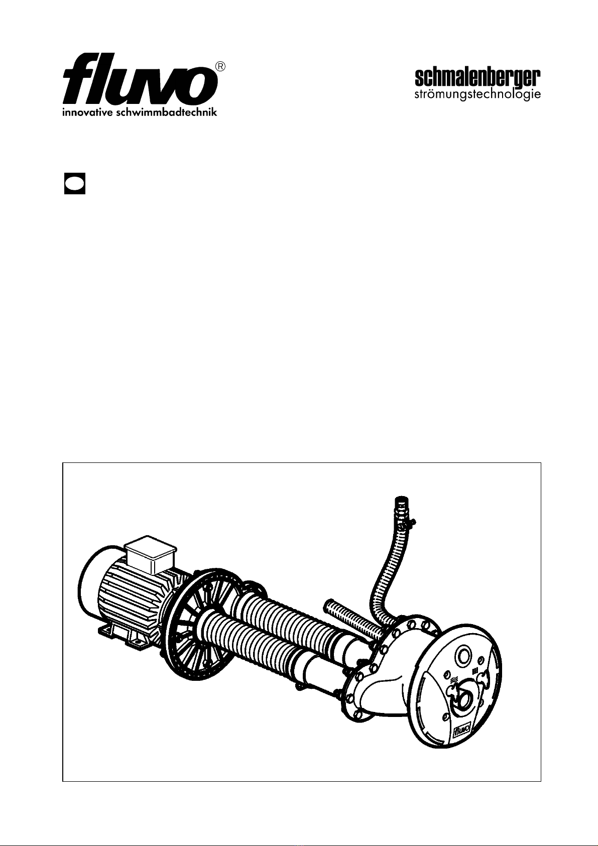
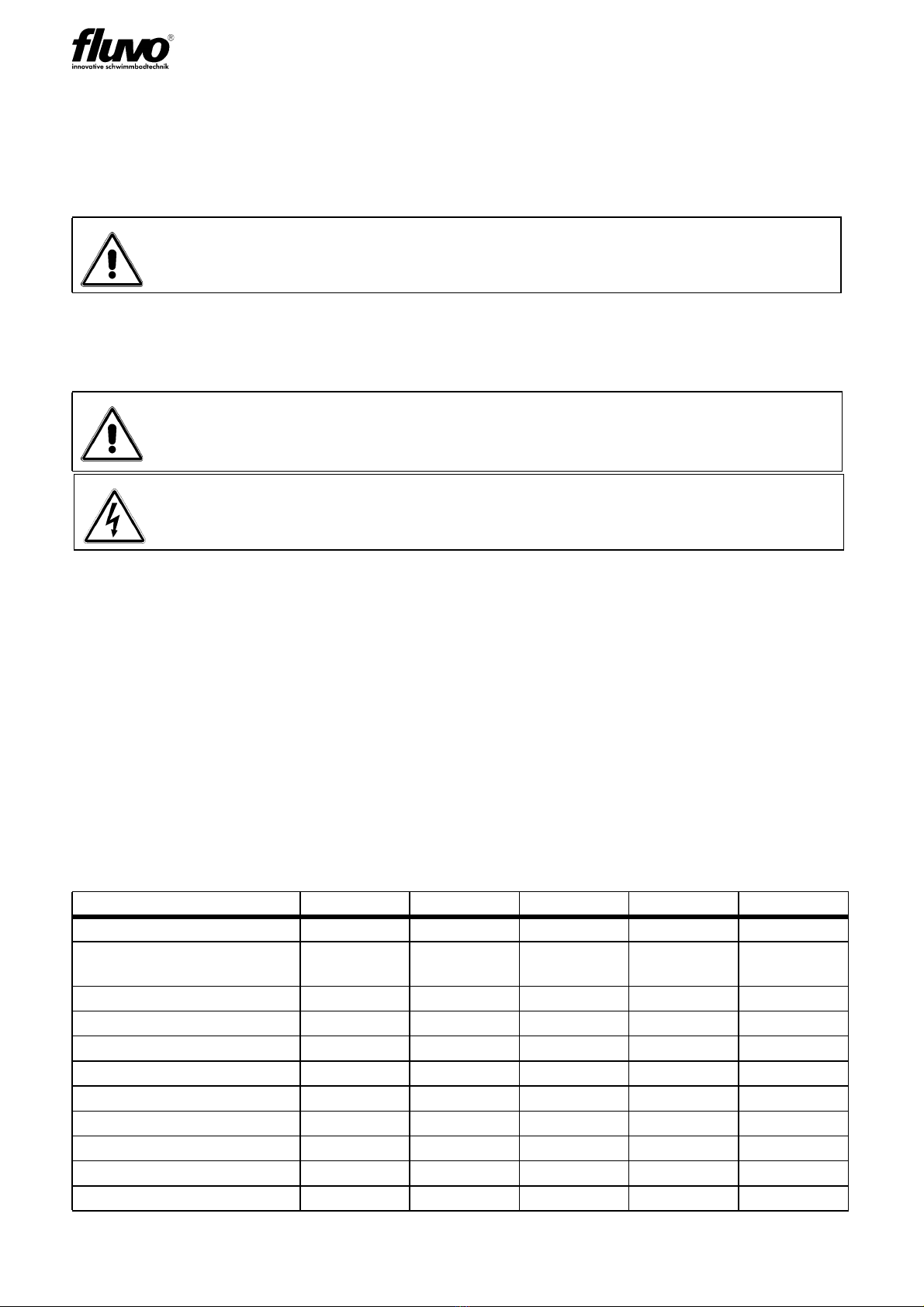
3.2 Device Units..................................................................................................................... 7
4 Installation Site Specifications / Installation .................................. 9
4.1 Base frames for the installation ....................................................................................... 9
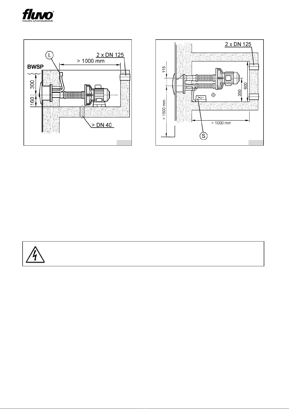
4.2 Planning the pump pit.................................................................................................... 10
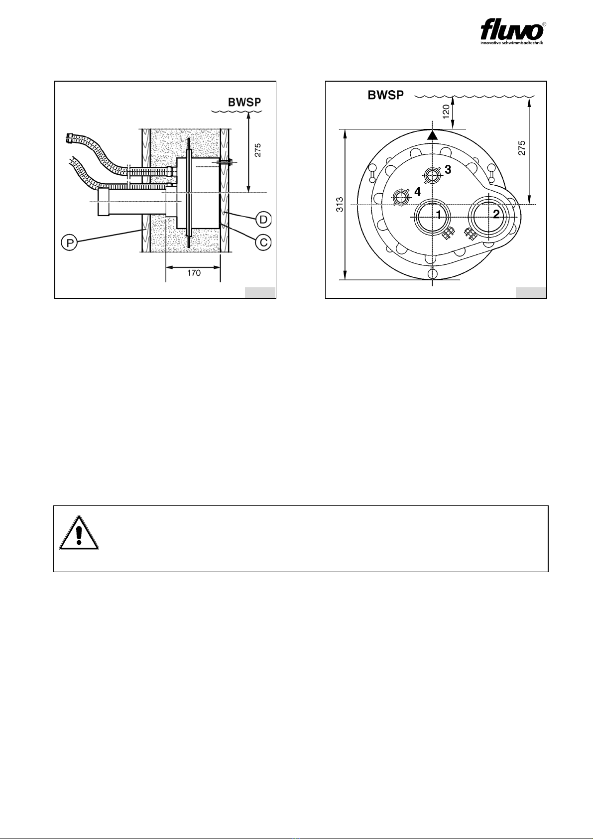
4.3 Installation preparations / Concrete pool ....................................................................... 11
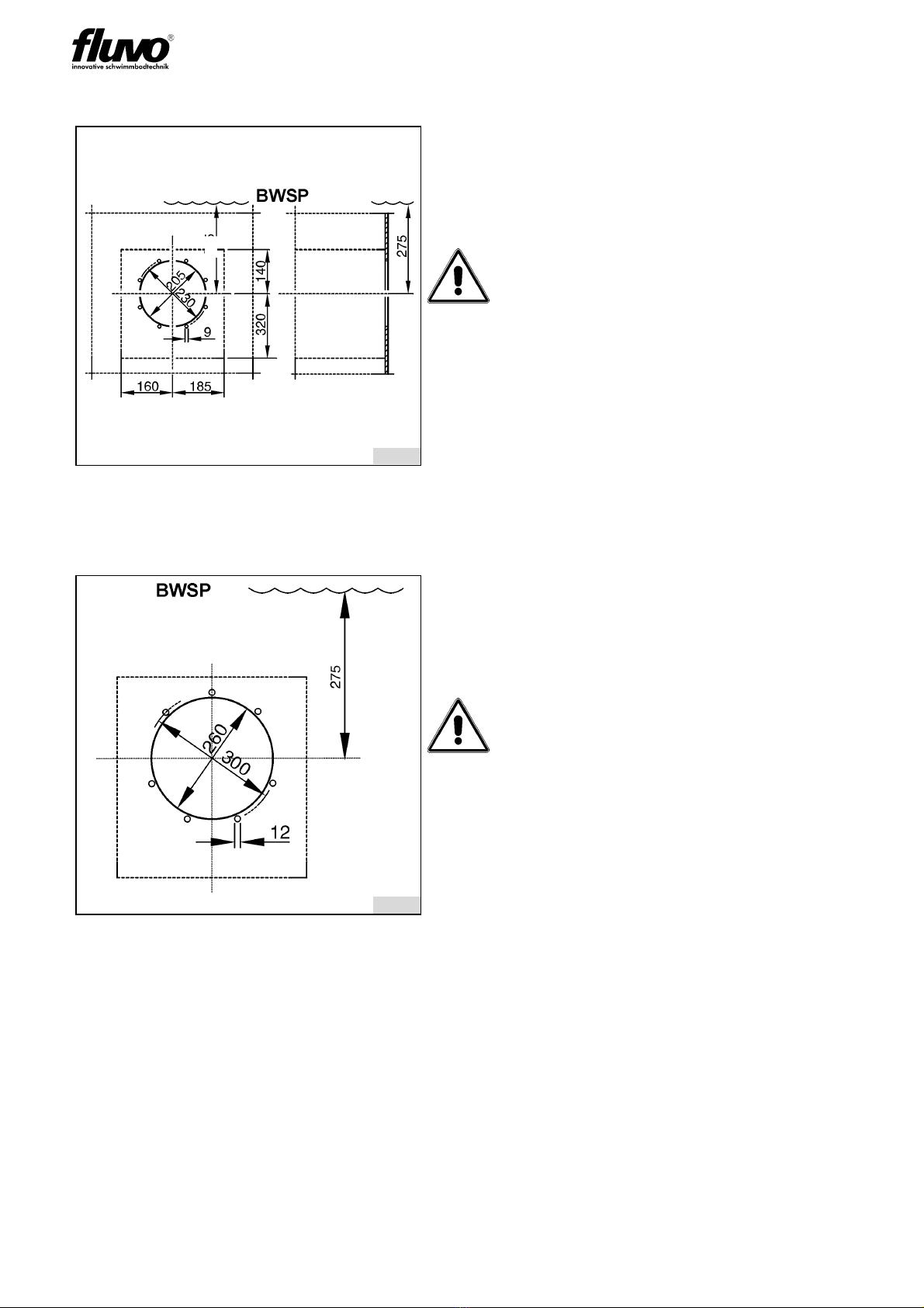
4.4 Installation preparations / Pre-fabricated pool ............................................................... 12
4.5 Installation preparations / Wooden-liner pool ............................................................... 12
4.6 Installation - general ...................................................................................................... 13
4.7 Mounting the installation kit / Pre-fabricated pool.......................................................... 14
4.8 Mounting the installation kit / Wooden-liner pool ........................................................... 15
4.9 Pump Kit Installation...................................................................................................... 16
4.10 Connection to the pool................................................................................................... 16
4.11 Connection to the pump................................................................................................. 17
4.12 Installing the switchgear cabinet.................................................................................... 17
4.13 Non-return air valve installation ..................................................................................... 18
4.14 Installation of the face plate assembly - general............................................................ 18
5 Electrical connections.................................................................... 19
5.1 Electrical Connections - general.................................................................................... 19
5.2 Electrical connections AC ............................................................................................. 20
5.3 Electrical connections three-phase current.................................................................... 20
6 Start-up / Operating ........................................................................ 21
7 Fault Assistance ............................................................................. 22
8 Shutdown / Overwintering.............................................................. 23
8.1 Empty the pool............................................................................................................... 23
8.2 Face plate assembly overwintering ............................................................................... 23
8.3 Draining the pump ......................................................................................................... 23
9 Maintenance and Repair................................................................. 24
9.1 General.......................................................................................................................... 24
9.2 Maintenance .................................................................................................................. 24
9.3 Repairs .......................................................................................................................... 24
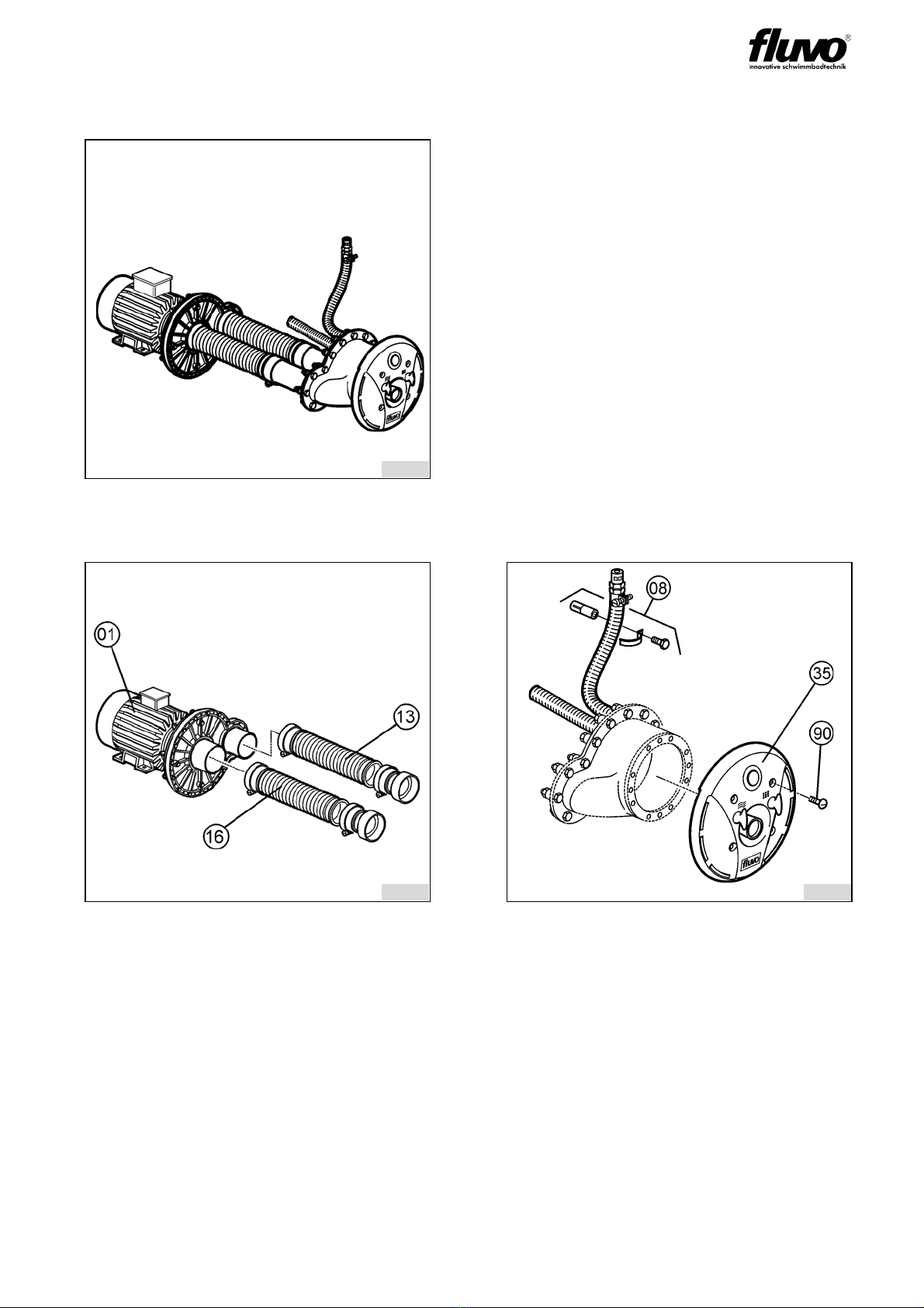
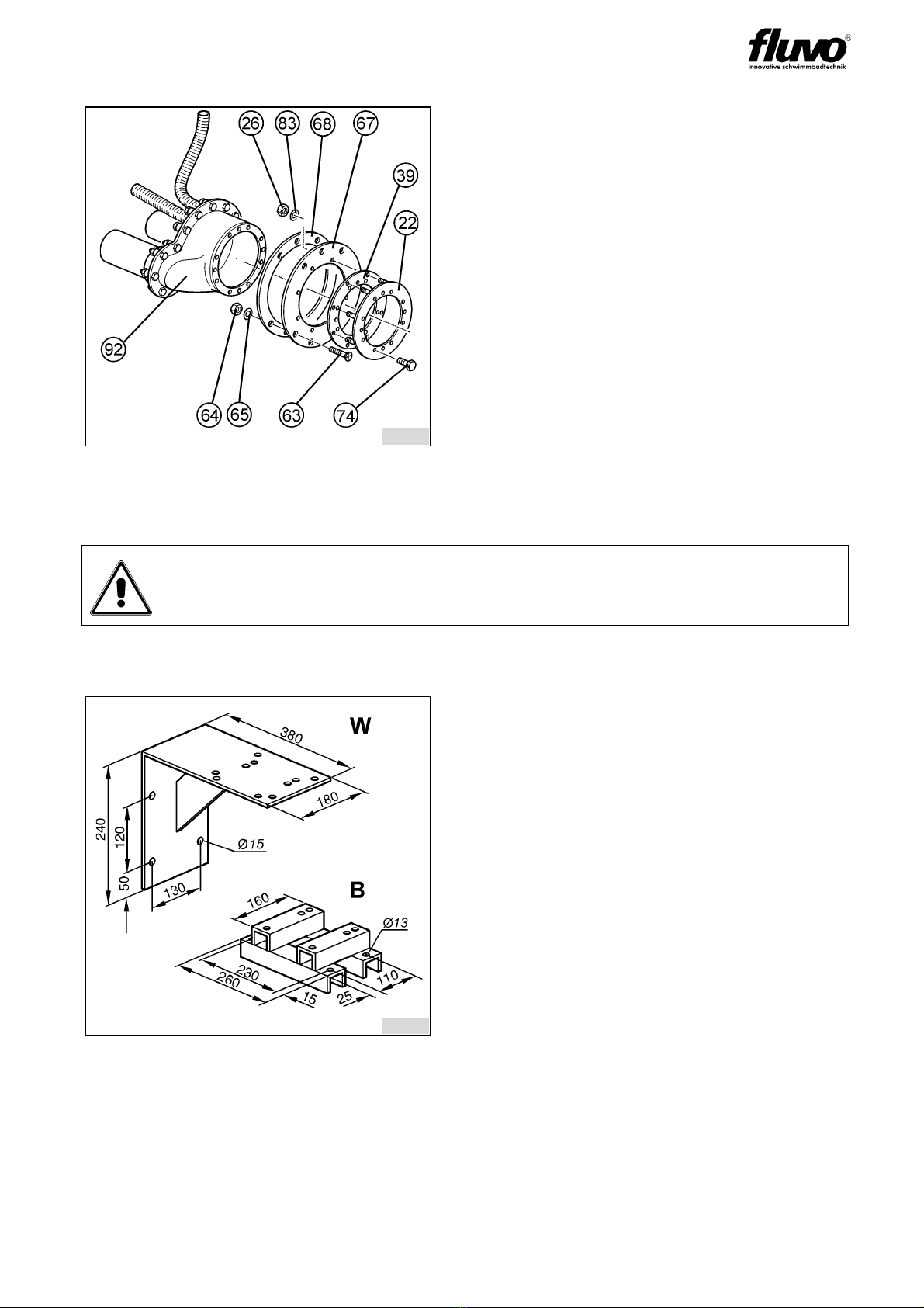
10 Spare parts ...................................................................................... 24
11 Spare Parts List and Drawing ....................................................... 121
11.1 Spare Parts List ............................................................................................................121
3
25
25

OPERATOR’S MANUAL
51C2G rondo
Version: 27201 - H Schmalenberger GmbH + Co. KG
D-72072 Tübingen / Germany
1 General
1.1 Guarantee notice
If the instructions contained in this operator’s manual are not observed then any claims
under guarantee shall be void.
1.2 General
All parts coming into contact with media are designed for water quality to DIN 19643.
The counter-current swimming unit (counter-current unit) is of state-of-the-art technology.
It has been manufactured with great care and is subject to constant quality checks. It has
been approved by the German Technical Inspectorate (TÜV) and awarded the TÜV-GS
(safety standard) mark.
The operator’s manual contains important instructions on how to use the counter-current
unit safely, properly and economically. The instructions must be strictly adhered to in order
to avoid danger and to ensure that the counter-current unit has a long useful life.
This manual does not take into account local regulations, the observance of which is the
responsibility of the operator – also on behalf of installation personnel that may be
involved.
The performance label specifies the machine series, the frame size, the most important
operating data and the serial number. Please be sure to quote it in case you require more
information and also when placing subsequent orders or ordering spare parts.
1.3 Usage Instructions
The counter-current unit was designed for use in private swimming pools. Consequently it
must not be installed in public swimming pools. Neither the entire unit nor parts thereof
must be used in other systems. You are expressly directed to use it only in accordance with
these instructions.
The counter-current unit must not be operated beyond the parameters stated in the
technical data (3.1). In case of doubt, please contact your customer service or the
manufacturer.
2 Safety Instructions
2.1 General
• Make sure that the relevant safety regulations and laws are observed in the operating
company and / or country where the counter-current units are to be used.
• All parts that come into contact with the medium are resistant to an absolute salt
content of up to 0.75% (4,500 mg/l Cl-). If the salt concentrations are greater than this,
the manufacturer must be consulted.
• Use the counter-current unit only if it is in perfect technical condition, in accordance with
the regulations, observing safety requirements and danger conditions and strictly
adhering to all the instructions in the operator’s manual!
• Promptly remedy any faults that could influence safety.
• Prior to carrying out repairs to the counter-current unit it must be isolated from the
electrical supply and protected from unintentional switching on.
• Regardless of what nature they may be, repairs must only be carried out by qualified
persons and the counter-current unit must be emptied first.
3

OPERATOR’S MANUAL
5 2 C2G rondo
Version: 27201 - H
Schmalenberger GmbH + Co. KG
D-72072 Tübingen / Germany
• The operator must ensure that
- the operator’s manual is always available for users to read,
- instructions in the operator’s manual are being observed,
- the counter-current unit is immediately stopped if abnormal electrical voltages,
temperatures, noises, vibrations, leakages or other faults should arise.
2.2 Symbols
In these operating instructions the following symbols are used to draw your special
attention to dangers:
Notices attached directly to the counter-current unit, e.g. the arrow indicating the direction
of rotation, must always be observed and maintained in a clearly legible condition.
3 Unit Description / General Technical Data
• The counter-current unit complies with VDE (Association of German Engineers)
regulations.
• The electric motor and the water conducting plastic pump are electrically separated.
• The electric motor complies with protection class IP 55.
• The entire counter-current unit complies with protection class I.
The counter-current unit is delivered as 3 assemblies:
1. Pump kit 2. Assembly kit 3. Installation kit
3.1 Technical Data
*WS = AC (alternating current)
For more details of safety instructions please see the brochure
Safety Instructions (27228-A).
Warning! Risk of injury! / Warning! Risk of damage!
This symbol warns you of dangers through mechanical effects and also warns
of handling that could damage the product.
Warning! Mortal danger!
This sign warns you of the danger from electric shocks.
System type: C2G 1,5 C2G 1,5 WS* C2G 1,9 C2G 1,9 WS* C2G 3,0
Capacity 1.5 kW 1.5 kW 1.9 kW 1.9 kW 3 kW
Voltage [V] 400 V Y /
230 V
230 V ~ 400 V Y /
230 V
230 V ~ 400 V Y /
230 V
Frequency 50 Hz 50 Hz 50 Hz 50 Hz 50 Hz
Current 3.3 / 5.6 A 9.5 A 4.4 / 7.6 A 11.8 A 6.5 / 11.5 A
Speed 2840 rpm 2790 rpm 2850 rpm 2820 rpm 2810 rpm
Delivery capacity 42 cbm/h 42 cbm/h 48 cbm/h 48 cbm/h 60 cbm/h
Delivery pressure 1.2 bar 1.2 bar 1.4 bar 1.4 bar 1.9 bar
Max. speed 2 m from the nozzle 1.15 m/sec. 1.15 m/sec. 1.3 m/sec. 1.3 m/sec. 1.6 m/sec.
Max. water temperature 50 °C 50 °C 50 °C 50 °C 50 °C
Expected sound pressure level 65 + 2 dB (A) 65 + 2 dB (A) 67 + 2 dB (A) 67 + 2 dB (A) 70 + 2 dB (A)
Weight 16 kg 17 kg 20 kg 21 kg 25 kg
4

OPERATOR’S MANUAL
53C2G rondo
Version: 27201 - H Schmalenberger GmbH + Co. KG
D-72072 Tübingen / Germany
3.2 Device Units
* The item numbers correspond to the numbers in the parts list.
fig. 1
Overview of the Counter-current
unit
The counter-current unit consists of:
1. Pump kit
2. Assembly kit
3. Installation kit
The installation kit is always different
depending on the pool type.
There are 4 kinds of pool:
- Concrete-tile pool
- Concrete-liner pool
- Pre-fabricated pool (steel,
plastic or similar)
- Wooden-liner pool
fig. 2 fig. 3
I - Pump kit
The pump kit consists of:
1. Pump assembly Item 01*
2. Suction hose Item 16
3. Pressure hose Item 13
*The pump kit is always identical no
matter what sort of pool it is intended for.
II - Assembly kit
The assembly kit includes:
1. Face plate assembly Item 35
2. Mounting screws Item 90
3. Air line fixing bracket Item 08
Note: There are two models of face plate
assembly depending on the pool type.
The model supplied to you can be found
in the spare parts list for your pool type.
8208
8209
8210
5

OPERATOR’S MANUAL
5 4 C2G rondo
Version: 27201 - H
Schmalenberger GmbH + Co. KG
D-72072 Tübingen / Germany
fig. 4
III - Installation kit for concrete-tile
pools
The installation kit consists of:
1. Housing Item 20
Note: The housing is concreted into the
concrete wall of the pool. Details of this
can be found in section chapter 4 of this
manual.
fig. 5 fig. 6
III - Installation kit for concrete-liner
pools
The installation kit consists of:
1. Installation kit Item 20
Note: The housing is concreted into the
concrete wall of the pool. Details of this
can be found in section 4 of this manual.
2. Clamp ring Item 72
3. Clamp gasket Item 32
4. Mounting screws Item 74
Note: Parts 2 to 4 are delivered with the
face plate assembly.
III - Installation kit for pre-fabricated
pools
The installation kit consists of:
1. Housing Item 91
2. Clamp ring Item 22
3. Clamp gasket Item 39
4. Hold-ring Item 62
5. Mounting screws Item 74
6. Nuts and washers Items 26+83
8211
8212
8413
6

OPERATOR’S MANUAL
55C2G rondo
Version: 27201 - H Schmalenberger GmbH + Co. KG
D-72072 Tübingen / Germany
4 Installation Site Specifications / Installation
4.1 Base frames for the installation
fig. 7
III - Installation kit for wooden-liner
pool
The installation kit consists of:
1. Housing Item 92
2. Clamp ring Item 22
3. Clamp gasket Item 39
4. Hold-ring Item 68
5. Hold-ring Item 67
6. Mounting screws Items 63+74
7. Nuts and washers Items 64/65
+26/83
Warning! Risk of damage!
As the pumps are not self-priming, the installation must be under water level.
Make sure you take this into account during the installation planning phase.
fig. 8:
There are two base frames available that
must be ordered separately to suit local
circumstances.
1. W = for wall mounting
2. B = for floor mounting
8414
8215
7

OPERATOR’S MANUAL
5 6 C2G rondo
Version: 27201 - H
Schmalenberger GmbH + Co. KG
D-72072 Tübingen / Germany
4.2 Planning the pump pit
When planning a pump duct take into account:
1. Clear dimensions min. 1000 x 600 x 600
2. Return connection min. 300 mm under the pool water level
3. Leakage water discharge pipe-end min. DN 40
4. Cooling air supply for the motor min. 2x DN 125. Minimum clearance of the motor
cooling air inlet to the wall = 200 mm.
5. Be sure to cover the pump pit if it is installed in the open air.
6. The position of the non-return air valve (L) must always be over the pool water level
(BWSP).
7. The position of the switchgear cabinet (S) must always be over the pool water level
(BWSP).
8. In case of leakage from the pump, a suitable water drainage must be provided!
fig. 9: Cross-sectional view of the pump
pit
fig. 10: Top view of the pump pit
BWSP Pool water level
L Air valve S Switchgear cabinet
Warning! Mortal danger!
The mains power supply cable must be equipped with an all-pole separator
with a contact opening of 3 mm.
8216
8217
8

OPERATOR’S MANUAL
57C2G rondo
Version: 27201 - H Schmalenberger GmbH + Co. KG
D-72072 Tübingen / Germany
4.3 Installation preparations / Concrete pool
Tailor the installation kit:
Place the installation kit on the formwork board and transfer the bore holes. Bore the holes
into the pool-side formwork board (D). Mark out and cut holes into the outer formwork
board (P) for the suction and pressure supplies and the two hoses.
Screw the installation kit complete with the mounting protection film (C) tightly to the pool-
side formwork board.
fig. 11 fig. 12: Rear view of the installation kit
BWSP Pool water level
C Mounting protection film
D Pool-side formwork board
P Outer formwork board
1 Pressure pipe DN 50
2 Suction pipe DN 65
3 Switching tube
4 Air supply to the non-return air
valve
Warning! Risk of damage!
• The installation kit must be horizontal.
• The distance between the centre of the installation kit and the water level
(BWSP) must be 275 mm.
8218
8219
9

OPERATOR’S MANUAL
5 8 C2G rondo
Version: 27201 - H
Schmalenberger GmbH + Co. KG
D-72072 Tübingen / Germany
4.4 Installation preparations / Pre-fabricated pool
4.5 Installation preparations / Wooden-liner pool
fig. 13: Boring diagram
Tailor the installation kit:
Cut the cavity Ø 205 and the mounting
holes Ø 9 into the pool wall.
Warning! Risk of damage!
The hold-ring (62) must be used as a
template.
For rear filling the pool ensure that there
is a cavity at least the size of the dotted
lines.
fig. 14: Boring diagram
Tailor the installation kit:
Cut the cavity Ø 260 and the mounting
holes Ø 12 into the pool wall.
Warning! Risk of damage!
The hold-ring (68) must be used as a
template.
Take note of the asymmetrical position of
the holes!
8220
88221
10

OPERATOR’S MANUAL
59C2G rondo
Version: 27201 - H Schmalenberger GmbH + Co. KG
D-72072 Tübingen / Germany
4.6 Installation - general
4.7 Mounting the installation kit / Pre-fabricated pool
fig. 15
Place the base frame in the desired
position. Fasten the base frame with 4
screws (S).
Warning!
The base frame should be installed in
such a way that it is insulated from the
floor and the wall (I) to avoid the
possibility of external voltage
transmissions.
I Insulation
SScrew
fig. 16
B Suction housing
22 Clamp ring
26 Nut
27 Distance washer
39 Clamp gasket
62 Hold-ring
74 Hexagon screw
91 Installation kit
Mount the clamp ring (22) with the clamp
gasket (39) and the hold-ring (62) to the
pool wall. The sealing contact faces
must be clean and smooth.
Then mount the housing (91) on the
clamp ring (22) with the screws (74).
Warning!
The housing (91) must be mounted so
that the connection for the membrane
switch (MS) is at the top.
8222
8223
11

OPERATOR’S MANUAL
6 0 C2G rondo
Version: 27201 - H
Schmalenberger GmbH + Co. KG
D-72072 Tübingen / Germany
4.8 Mounting the installation kit / Wooden-liner pool
Mount the hold-ring (67) with the distance washer (68) to the pool wall.
Hang in the liner. Fasten the liner and the clamp gasket (39) together with the clamp ring
(22) and cut out the liner.
Then mount the installation kit (92) on the clamp ring (22) with the screws (74). See also
detail “N” in fig. 18.
fig. 17 fig. 18: Detail from fig. 17
B Pool wall
N For details see fig. 18
BWSP Pool water level
20 Installation kit
22 Clamp ring
26 Nut
27 Distance washer
39 Clamp gasket
63 Countersunk screw
67 Hold-ring
68 Hold-ring
74 Screw
83 Distance washer
92 Installation kit
Warning!
The installation kit (92) must be mounted so that the connection for the
membrane switch is at the top.
8224
8225
12

OPERATOR’S MANUAL
61C2G rondo
Version: 27201 - H Schmalenberger GmbH + Co. KG
D-72072 Tübingen / Germany
4.9 Pump Kit Installation
4.10 Connection to the pool
fig. 19
R Pipework
S Hexagon screws
V Adaptor
Mount the pump free of all tension with
the hexagon screws M8 (S) on the base
frame.
Warning!
1. Do not use any vibration dampers
between the pump and the base frame.
2. If the pipework (R) to the pump is longer
than 6 m then the nominal width must
be increased.
- Suction side from DN 65 to a min.
of DN 80
- Pressure side from DN 50 to a min.
of DN 65.
3. Then always mount the adaptors (V) on
the pump body.
fig. 20
14 Return connection
17 Suction connection
20 / 91 / 92 Installation kit
Stick the adaptors (14+17) to the pipe
connection on the installation kit (20/91/
92). Alternatively, by using pipework,
stick to the pump-side end of the
pipework.
Warning!
Always be sure to lay the pipework using
bends and not angles to keep the pipe
resistance to a minimum.
8226
8227
13

OPERATOR’S MANUAL
6 2 C2G rondo
Version: 27201 - H
Schmalenberger GmbH + Co. KG
D-72072 Tübingen / Germany
4.11 Connection to the pump
4.12 Installing the switchgear cabinet
fig. 21
01 Motor
12 Air pipe clamp
13 Hose line pressure side
16 Hose line suction side
Connect the hose lines (13 pressure side
+ 16 suction side) to the pump body. Use
the corresponding air pipe clamps (12)
on both sides for this.
Warning!
Make sure that the connections from the
body of the pump to the installation kit /
pipework are as nearly aligned as is
possible.
The hose lines must always be attached
to the pump on the one side
(compensator function), see diagram.
fig. 22
For electrical connection information
regarding the Control NT panel, please
refer to the corresponding instruction
manual 27248
8228
14

OPERATOR’S MANUAL
63C2G rondo
Version: 27201 - H Schmalenberger GmbH + Co. KG
D-72072 Tübingen / Germany
4.13 Non-return air valve installation
4.14 Installation of the face plate assembly - general
fig. 23
LAirhose
28 Non-return air valve
29 Air line hose tail
30 Hose tail
52 Air pipe clamp
56 Fixing bracket
Connect the non-return air valve (28) and
the air line hose tail (29) to the air hose
(L). Warm the air hose (L) up prior to
connecting. Fasten with the air pipe
clamp (52).
Fasten the non-return air valve with the
fixing bracket (56) to the pool wall or
similar. In the case of a ground level
overflow, place the non-return air valve in
the duct, see detail “B”.
Warning!
To position the non-return air valve also please observe the information under
chapter 4.2.
fig. 24
A Hose coupling
B Plug sleeve
D Face plate assembly
21 Hose
Drain the pool water, if already filled, to
below the installation kit. Firmly place the
hose (21) with the hose coupling (A) onto
the plug sleeve (B) on the face plate
assembly (D). With that the air button is
connected to the switchgear cabinet.
8230
8231
15

OPERATOR’S MANUAL
6 4 C2G rondo
Version: 27201 - H
Schmalenberger GmbH + Co. KG
D-72072 Tübingen / Germany
4.14.1 Face plate assembly installation / Concrete-tile pool
4.14.2 Face plate assembly installation / Concrete-liner pool
After connecting the air button, put on the face plate assembly (35), this allows the
pressure connection and air connection to slide into one another (refer to fig. 24). Fasten
to the clamp ring (72) with the screws (90.2).
fig. 25
C Mounting protection film
20 Installation kit
21 Switching tube
35 Face plate assembly
90 Screw
Remove the mounting protection film (C).
After connecting the air button, put on the
face plate assembly (35), this allows the
pressure connection and air connection
to slide into one another. Fasten to the
installation kit (20) with the screws (90).
Warning!
Make sure that there is not a kink in the
switching tube (21), lay it in a loop and do
not shorten!
fig. 26
C Mounting protection film
20 Installation kit
21 Switching tube
32 Clamp gasket
35 Face plate assembly
72 Clamp ring
74 Screw
90 Screw
Remove the mounting protection film (C).
Place the clamp gasket (32) between the
installation housing and the liner and
screw the clamp ring (72) to the
installation housing using the screws
(74). The sealing contact faces must be
clean and smooth. Now cut out the pool
liner.
Warning!
Make sure that there is not a kink in the switching tube (21), lay it in a loop and
do not shorten!
8232
8233
16

OPERATOR’S MANUAL
65C2G rondo
Version: 27201 - H Schmalenberger GmbH + Co. KG
D-72072 Tübingen / Germany
4.14.3 Face plate assembly installation / Pre-fabricated pool
4.14.4 Face plate assembly installation / Wooden-liner pool
5 Electrical connections
5.1 Electrical Connections - general
The electrical connections to the counter-current swimming system must be carried out by
a specialised company in the electrical engineering branch approved by the local energy
provider, taking into account the technical connection requirements.
fig. 27
21 Switching tube
22 Clamp ring
35 Face plate assembly
90 Screw
After connecting the air button, put on the
face plate assembly (35), this allows the
pressure connection and air connection
to slide into one another. Fasten to the
clamp ring (22) with the screws (90).
Warning!
Make sure that there is not a kink in the
switching tube (21), lay it in a loop and do
not shorten!
fig. 28
21 Switching tube
22 Clamp ring
35 Face plate assembly
90 Screw
92 Installation kit
After connecting the air button, put on the
face plate assembly (35), this allows the
pressure connection and air connection
to slide into one another. Fasten to the
clamp ring (22) with the screws (90).
Warning!
Make sure that there is not a kink in the
switching tube (21), lay it in a loop and do
not shorten!
8234
8235
17

OPERATOR’S MANUAL
6 6 C2G rondo
Version: 27201 - H
Schmalenberger GmbH + Co. KG
D-72072 Tübingen / Germany
• The mains power connection must be a fixed connection.
• Under no circumstances must there be any conducting connection between the metal
parts of the motor and the water.
• An earth leakage circuit breaker (nominal fault current 30 mA) must be fitted to the
mains power connection.
• At the marked connection terminal (at the foot of the motor or next to the terminal box)
an equalising potential with a cross-section of 10 mm² must be fitted.
5.2 Electrical connections AC
Warning! Mortal danger!
The connections must be carried out by a qualified electrician. For this see for
example the Technical Connection Conditions for heavy Current from the
power supply company , the Regulations of the Electrical Trade VBG (§3)
and DIN VDE 1000-10 / 1995-5. The relevant DIN VDE directives 0100 and
where there is a risk of explosion 0165 must also be observed. If the installation
is not carried out properly, there is a risk of getting electric shocks!
Warning!
Compare the available power supply voltage with the details on the motor’s
factory plate and select the appropriate switching.
We recommend the use of a motor protection facility. Explosion protected
motors, increased safety (Ex)–e and temperature class T3, must always be
connected in accordance with DIN VDE 0170/0171 via a motor protection
switch.
Connect the motor in accordance with the circuit diagrams in the following
chapters.
fig. 29
Mains voltage 230 V for 1 ~ AC
Mains power supply cable: 3 x 2.5 mm²
Pump power supply cable: 3 x 2.5 mm²
Fuse: 16 A passive
B = Control unit in the pool
M = Motor of the circulation pump
N = Mains power supply
(230 V for 1~)
S = Switchgear cabinet
C B= Capacitor
Connection cable, for example,
HO7RNF, all further details required for
making connections can be found in
chapter 3.1.
8236
18

OPERATOR’S MANUAL
67C2G rondo
Version: 27201 - H Schmalenberger GmbH + Co. KG
D-72072 Tübingen / Germany
Protective measures:
5.3 Electrical connections three-phase current
fig. 30: Basic circuit diagram for 230 V
for 1 ~ AC
An earth leakage circuit breaker
(nominal fault current 30 mA) must be
fitted to the mains power supply!
Important! Watch the order of the
terminal bridges!
See the inside of the terminal box lid or
enclosed circuit diagram. Please be sure
to observe instructions from the motor
manufacturer!
L External conductor
N Neutral conductor
fig. 31: Basic circuit diagram for 400/
230 V three-phase current
Mains voltage: 400/230 V for
3 ~ current
Mains power supply
connection cable: 5 x 2.5 mm²
Pump power supply cable: 4 x 2.5 mm²
Fuse: 16A passive
B = Control unit in the pool
M = Motor of the circulation pump
N = Mains power supply
(400/230 V 3 ~)
S = Switchgear cabinet
Connection cable, for example,
HO7RNF, all further details required for
making connections can be found in
chapter 3.1.
8206
8238
19

OPERATOR’S MANUAL
6 8 C2G rondo
Version: 27201 - H
Schmalenberger GmbH + Co. KG
D-72072 Tübingen / Germany
Protective measures:
6 Start-up / Operating
Never carry out a trial run with the motor as long as there is no water in the pump. A dry
run will destroy the mechanical seal in the pump!
• Switching the pump on and off
The pump is switched on by pressing the switching button (Z). After 2 seconds the pump
can be switched off by pressing the button again or a signal can be sent to the pump (on-
off function).
fig. 32: Basic circuit diagram for 400/
230 V three-phase current
An earth leakage circuit breaker
(nominal fault current 30 mA) must be
fitted to the mains power supply!
Important! Watch the order of the
terminal bridges!
See the inside of the terminal box lid or
enclosed circuit diagram. Please be sure
to observe instructions from the motor
manufacturer!
L External conductor
N Neutral conductor
Abb. 38
KLAir supply regulator knob
KWWater supply regulatorknob
Q Nozzle
Z Switching button
8239
8322
20
Table of contents
Other schmalenberger Industrial Equipment manuals
Popular Industrial Equipment manuals by other brands

Siemens
Siemens SCALANCE XR124WG manual

Spirax Sarco
Spirax Sarco AE50S Installation and maintenance instructions

DRIESCHER-WEGBERG
DRIESCHER-WEGBERG MINEX-C ABS zero Operation and assembly instructions

Klutch
Klutch 49699 owner's manual

Northern
Northern TELEHANDLER Operation guidelines

Jäger
Jäger Z62-M260.01 S2 manual

Valiani
Valiani Astra 120 Use and maintenance

Elecro Engineering
Elecro Engineering SST Installation & operating manual

FRC
FRC GOVERNOR PRO 3 operating instructions

MachineryHouse
MachineryHouse SIEG SUPER X3 instruction manual

Eaton
Eaton Power Defense Instruction leaflet

ESAB
ESAB GASARC GPE 400 Series Installation & operating instructions