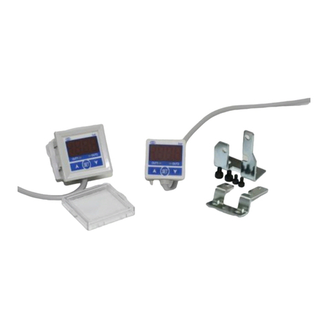
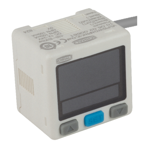
Schmalz VS-V-W-D PNP K 3C-D User manual

Vacuum/pressure switch VS-V/P-W-D K 3C-D
Operating Instructions
WWW.SCHMALZ.COM EN-US · 30.30.01.01858 · 00 · 04/19

Note
The operating instructions were originally written in German. Store in a safe place for future reference.
Subject to technical changes without notice. No responsibility is taken for printing or other types of er-
rors.
Published by
© J.SchmalzGmbH, 04/19
This document is protected by copyright. J.SchmalzGmbH retains the rights established thereby. Repro-
duction of the contents, in full or in part, is only permitted within the limits of the legal provisions of
copyright law. Any modifications to or abridgments of the document are prohibited without explicit writ-
ten agreement from J.SchmalzGmbH.
Contact
J. Schmalz GmbH
Johannes-Schmalz-Str. 1
72293 Glatten, Germany
T: +49 7443 2403-0
www.schmalz.com
Contact information for Schmalz companies and trade partners worldwide can be found at:
www.schmalz.com/salesnetwork
2 / 26 EN-US · 30.30.01.01858 · 00 · 04/19

EN-US · 30.30.01.01858 · 00 · 04/19 3 / 26
1 Important information ...................................................................................................................................5
1.1 Note on Using this Document ............................................................................................................... 5
1.2 The technical documentation is part of the product ........................................................................... 5
1.3 Warnings in this document.................................................................................................................... 5
1.4 Symbol..................................................................................................................................................... 5
2 Fundamental Safety Instructions...................................................................................................................6
2.1 Intended use ........................................................................................................................................... 6
2.2 Non-Intended Use .................................................................................................................................. 6
2.3 Personnel Qualification.......................................................................................................................... 6
2.4 Modifications to the Product................................................................................................................. 6
3 Product description.........................................................................................................................................7
3.1 Variants and Type Key ........................................................................................................................... 7
3.2 Design of vacuum/pressure switch ........................................................................................................ 7
3.3 Display and Operating Element in Detail ............................................................................................. 8
4 Technical Data .................................................................................................................................................9
4.1 General Parameters................................................................................................................................ 9
4.2 Dimensions............................................................................................................................................ 10
5 Installation.....................................................................................................................................................11
5.1 Mounting .............................................................................................................................................. 11
5.2 Pneumatically Connecting the Switch................................................................................................. 11
5.3 Electrical Connection............................................................................................................................ 11
6 Operation ......................................................................................................................................................13
6.1 Safety Instructions ................................................................................................................................ 13
6.2 Setting Up the Basic Functions ............................................................................................................ 13
6.3 Functions in the Main Menu................................................................................................................ 13
6.4 Functions in the Additional Functions Menu ..................................................................................... 14
6.5 Energy-Saving Function ....................................................................................................................... 15
6.6 Setting the Zero Point.......................................................................................................................... 15
6.7 Setting the Vacuum or Pressure Unit .................................................................................................. 16
6.8 Setting the Switching Point ................................................................................................................. 16
6.8.1 Setting the Switching Points for One Output.......................................................................... 16
6.8.2 Setting the Switching Points for Two Outputs ........................................................................ 17
6.9 Locking the Keypad.............................................................................................................................. 18
6.10 Displaying the Maximum and Minimum Values of the Measured Values........................................ 18
6.11 Fine Adjustment of the Display Values ............................................................................................... 19
6.12 Switching Logic..................................................................................................................................... 20
6.13 Voltage Profiles of the Analog Output............................................................................................... 20
7 Troubleshooting............................................................................................................................................21
8 Accessories ....................................................................................................................................................22
8.1 Accessory Items..................................................................................................................................... 22
8.2 Mounting Accessories .......................................................................................................................... 22

Important information
EN-US · 30.30.01.01858 · 00 · 04/19 5 / 26
1Important information
1.1Note on Using this Document
J.SchmalzGmbH is generally referred to as Schmalz in this operating instructions.
These operating instructions contain important notes and information about the different operating
phases of the product:
• Transport, storage, start of operations and decommissioning
• Safe operation, required maintenance, rectification of any faults
The operating instructions describe the product at the time of delivery by Schmalz.
1.2The technical documentation is part of the product
1. For problem-free and safe operation, follow the instructions in the documents.
2. Keep the technical documentation in close proximity to the product. The documentation must be ac-
cessible to personnel at all times.
3. Pass on the technical documentation to subsequent users.
ðFailure to follow the instructions in this operating instructions may result in life-threatening injuries!
ðSchmalz is not liable for damage or malfunctions that result from failure to heed these instructions.
If you still have questions after reading the technical documentation, contact Schmalz-service at:
www.schmalz.com/services
1.3Warnings in this document
Warnings warn against hazards that may occur when handling the product. This document contains three
levels of danger that you can recognize by the signal word.
Signal word Meaning
WARNING Indicates a medium-risk hazard which, if not avoided, could result in death or
serious injury.
CAUTION Indicates a low-risk hazard which, if not avoided, could result in minor or
moderate injury.
NOTE Indicates a danger that leads to property damage.
1.4Symbol
This sign indicates useful and important information.
üThis symbol represents a prerequisite that must be met before an action is performed.
4This sign represents an action to be performed.
ðThis sign represents the result of an action.
Actions that consist of more than one step are numbered:
1. First action to be performed.
2. Second action to be performed.

Fundamental Safety Instructions
6 / 26 EN-US · 30.30.01.01858 · 00 · 04/19
2Fundamental Safety Instructions
2.1Intended use
The Vacuum/pressure switch is used for measuring and displaying vacuum power or pressure and outputs
it proportionally as an electrical voltage from 1 to 5V on an analog output.
This device has been designed, developed and constructed solely for industrial and commercial use. Pri-
vate use is excluded.
The Vacuum/pressure switch is built in accordance with the latest standards of technology and is shipped
in safe condition. However, hazards can arise during use.
Intended use includes the observance of the technical data and the installation and operating instructions
in this manual.
2.2Non-Intended Use
Schmalz accepts no liability for damages caused by the use of the Vacuum/pressure switch for purposes
other than those described under "Intended Use."
Non-intended use includes the following:
• Use in potentially explosive atmospheres
2.3Personnel Qualification
Unqualified personnel cannot recognize dangers and are therefore exposed to higher risks!
1. Only instruct qualified personnel to perform the tasks described in these operating instructions.
2. The product may only be operated by persons who have undergone appropriate training.
3. Electrical work and installations may only be carried out by qualified electrical specialists.
4. Assembly and maintenance work must only be carried out by qualified personnel.
2.4Modifications to the Product
Schmalz assumes no liability for consequences of modifications over which it has no control:
1. The product must be operated only in its original condition as delivered.
2. Use only original spare parts from Schmalz.
3. The product must be operated only in perfect condition.

Product description
EN-US · 30.30.01.01858 · 00 · 04/19 7 / 26
3Product description
3.1Variants and Type Key
The product description of the Vacuum/pressure switch is composed of the following type key:
Pressure range
Output specification
VP1: Pressure/vacuum (-1.030~1.030 bar)
V :vacuum (0.100~-1.030 bar)
P10: Positive (-1.03~10.30 bar)
NPN: 2 NPN output / 1 NPN output + Analog output (1–5V)
PNP: 2 PNP output / 1 PNP output + Analog output (1–5V)
Part no. Type key Pressure range Outputs
10.06.02.00678 VS-V-W-D PNP K 3C-D Vacuum (0.1 to 1.03 bar) 2 PNP
10.06.02.00679 VS-V-W-D NPN K 3C-D Vacuum (0.1 to 1.03 bar) 2 NPN
10.06.02.00680 VS-P10-W-D PNP K 3C-D Pressure (-1.03 to 10.30 bar) 2 PNP
10.06.02.00681 VS-P10-W-D NPN K 3C-D Pressure (-1.03 to 10.30 bar) 2 NPN
10.06.02.00703 VS-VP1-W-D PNP K 3C-D Pressure/vacuum (-1.03 to 1.03 bar) 1 PNP
10.06.02.00702 VS-VP1-W-D NPN K 3C-D Pressure/vacuum (-1.03 to 1.03 bar) 1 NPN
3.2Design of vacuum/pressure switch
1UP BUTTON
1
4
3
2
6
8
5
7
2 Display
3DOWN BUTTON
4SET BUTTON
5 Electrical connection/con-
nection cable
6 Measuring medium
7 O-ring
8 Mounting thread 2xM5

Product description
8 / 26 EN-US · 30.30.01.01858 · 00 · 04/19
3.3Display and Operating Element in Detail
The Vacuum/pressure switch display and operating element features 3 buttons and two display areas.
1 Display for output 1
1
3
4
8 7
6
5
9
2
2 Display for output 2
3 Lock indicator
4 Unit for pressure display
5 Main display area, two-colored
6 Setting mode of lower display area
7DOWN BUTTON
8SET BUTTON
9UP BUTTON
Pressure definition with selected display unit depending on the vacuum switch version:
Selected unit Display definition for variant
VS-V... and VS-VP1...
Display definition for variant
VS-P10...
kPa 0.1 —
MPa — 0.001
kgf/cm20.001 0.01
bar 0.001 0.01
psi 0.01 0.1
inHg 0.1 —
mmHg 1 —

Technical Data
EN-US · 30.30.01.01858 · 00 · 04/19 9 / 26
4Technical Data
4.1General Parameters
Parameter Unit Value for VS-V... Value for VS-P10... Value for VS-VP1...
Measuring medium — Non-aggressive, flammable gases; dry, oil-free air
Measurement range bar -1.03 to 0.00 -1.0 to 10.0 -1.0 to 1.0
Adjustable range bar -1.03 to 0.10 -1.03 to 10.3 -1.03 to 1.03
Max. overpressure re-
sistance
bar 5 15 5
Factory setting bar H1: -0.75
L1: -0.60
H2: -0.55
L2: -0.50
NO mode
H1: 5.50
L1: 5.00
H2: 5.00
L2: 4.50
NO mode
H1: - 0.60
L1: -0.75
H2: 0.55
L2: 0.50
NO mode
Supply voltage — 12 to 24VDC ± 10%,
ripple (P-P) 10% or less
Current consumption mA ≤30 (without load)
Switching output,
type
— Open collector 2 outputs (NPN or PNP)
Switching output,
electricity
mA Max. 100
Switching output,
residual voltage
V≤1
Resistance, output kΩ— 1
Voltage, output V — 1~5 ±2.5% F.S.
Linearity, output — —
Switching output, re-
sponse time
ms ≤2.5
(can be set to 25, 100, 250, 500, 1000 and 1500)
Display — 2-color main display (red/green); 1-color additional display (or-
ange),
sample rate: 0.2, 0.5, 1 second / time selectable
Display accuracy — ±1% F.S. ±1 digit (ambient temperature: 25 ±3°C)
Repeatability (switch-
ing output)
— ±0.3% F.S. ±1 digit
Vacuum/pressure
switch display
switched on
— Orange OUT display
Degree of protection
IP
— IP40
Operating tempera-
ture
°C 0 to 50
Temperature charac-
teristic
°C ± 2% F.S. of the recorded pressure (25°C) for a temperature range
of 0 to 50
Storage temperature °C -10 to 60 (no condensation, not freezing)
Permitted humidity % RH 35 to 85 (no condensation)
Withstand voltage — 1000VAC in 1 min. (between housing and connection cable)
Insulation resistance — 50MΩ (at 500VDC, between housing and connection cable)

Technical Data
10 / 26 EN-US · 30.30.01.01858 · 00 · 04/19
Parameter Unit Value for VS-V... Value for VS-P10... Value for VS-VP1...
Vibration — Total amplitude 1.5 mm, 10 Hz ~ 150 Hz ~ 10 Hz for 1 minute, two
hours in each direction X, Y and Z
Shock strength — 100m/s² (10G), 3 times each in the direction of X, Y and Z
Measuring medium
connection
— 1/8" external thread
Electrical connection — Oil-resistant cable (0.15 mm2), 4-pole
Weight g Approx. 67 (incl. 2-m cable)
4.2Dimensions
B G1 G2 G4 H H1 L LG1 LG2 LG4 Lk X1 Y1
30 1/8" ex-
ternal
thread
M5 in-
ternal
thread
M3 in-
ternal
thread
21.3 36.3 30 9 10 4.5 2000 20 20
All specifications are in mm

Installation
EN-US · 30.30.01.01858 · 00 · 04/19 11 / 26
5Installation
5.1Mounting
The sensor may be installed in any position.
To ensure correct function and to prevent faults in the sensor, observe the following installation instruc-
tions:
Do not drop the Vacuum/pressure switch, and do not subject it to excessive impacts. Even if the switch
housing is undamaged, internal components may be damaged, resulting in malfunction.
üTwo M5 fastening screws are provided by the customer.
4To mount the Vacuum/pressure switch, use the
two M5 threads.
The length of the screws must be limited to 5 mm. Do not use standard screws!
5.2Pneumatically Connecting the Switch
4The pneumatic connection uses a G1 or G2
thread. Connect suitable pipelines with the
appropriate connection. To connect the hex
socket or connector, hold the hexagonal part
of the pneumatic connector tight and secure
it. Use a tightening torque of 13 Nm or less.
5.3Electrical Connection
NOTE
Incorrect power supply
Destruction of the integrated electronics
4Operate the product using a power supply unit with protected extra-low voltage
(PELV).
4The system must incorporate safe electrical cut-off of the power supply in compliance
with EN60204.
4Do not connect or disconnect the connector under tension and/or when voltage is ap-
plied.

Installation
12 / 26 EN-US · 30.30.01.01858 · 00 · 04/19
NOTE
Connect with the power turned on
Damage to the electronics and/or malfunction
4Switch off the power supply before connecting cables!
The vacuum switch is supplied with a 4-wire connection cable with open cable ends.
Integrate the Vacuum/pressure switch into your application in accordance with the electrical circuit dia-
gram.
Electrical Circuit Diagrams
VS-VP1-W-D NPN K 3C-D (1 NPN+Analog Output
(1–5V))
VS-VP1-W-D PNP K 3C-D (1 PNP+Analog Output
(1–5V))
OUT Analog
OUT Analog
VS-☐-W-D NPN K 3C-D (2 NPN Output) VS-☐-W-D PNP K 3C-D (2 PNP Output)
Assignment of Cable Colors
Cable Cable color
DC (+) Brown
OUT1 Black
OUT2 / OUT Analog White
DC (-) Blue
Lay the connection cables of the pressure switch separately. Electrical interference can cause malfunctions
if the cable is routed together with mains or high voltage cables.
Establish a ground connection when using a standard cable.
When the switching regulator is connected to the pressure switch, the switching signals are superimposed
and the product specification is no longer fulfilled. This can be prevented by inserting a noise filter (mains
noise filter, ferrite element) between the switching regulator and the pressure switch, or by using a serial
power supply instead of a switching regulator.

Operation
EN-US · 30.30.01.01858 · 00 · 04/19 13 / 26
6Operation
6.1Safety Instructions
NOTE
Operating pressure above the recommended maximum pressure
Damage to the switch
4Only use the Vacuum/pressure switch within the nominal pressure range.
Do not drop the vacuum switch or subject it to impacts.
Even if the housing is undamaged, internal components may be damaged and cause malfunction.
6.2Setting Up the Basic Functions
The Vacuum/pressure switch is operated using three buttons:
SET BUTTON
UP BUTTON
DOWN BUTTON
Settings are configured in software menus.
The following menus are available:
• Main menu: For standard applications
• Additional Functions menu: For applications with special requirements
Activating the Main Menu and Selecting Parameters
üThe Vacuum/pressure switch is in Measurement mode.
1. Press the button for at least three seconds.
ðThe first parameter in the main menu is selected. This is indicated by ot1 in the lower display.
2. Press the or button to select the desired function mode for the OUT1 output.
3. By pressing the button, the next parameter is selected and the selected or set parameter value
is accepted.
6.3Functions in the Main Menu
The following table shows an overview of the display codes and parameters in the main menu:
Parameter Display code
for the lower
display
Display code
for the main
display
Explanation
OUT1 output
operating mode
ot1 oP5 One point set mode
XY5 Hysteresis mode
Window Comparator mode
OUT1 output
Switching logic
no "normally open" NO mode
nC "normally open" NC mode
OUT2 output
operating mode
ot2 oFF Output 2 deactivated
oP5 One point set mode

Operation
14 / 26 EN-US · 30.30.01.01858 · 00 · 04/19
Parameter Display code
for the lower
display
Display code
for the main
display
Explanation
This selection will not be dis-
played if only one output is avail-
able.
XY5 Hysteresis mode
Window Comparator mode
OUT2 output
Switching logic
This selection will not be dis-
played if only one output is avail-
able or if output 2 is deactivated
(off).
no "normally open" NO mode
nC "normally open" NC mode
Response time rE5 2.5
25
100
250
500
1000
1500
2.5ms
25ms
100ms
250ms
500ms
1000ms
1500ms
Display color CoL 5or
5oG
rEd
Grn
ON: red, OFF: green
ON: green, OFF: red
ON/OFF: red
ON/OFF: green
Display unit uni bAr
GF
PA
P5i
inX
nnX
Shown in bar
Shown in kgf/cm2
Shown in kPa / MPa
Shown in psi
Shown in inHg 1)
Shown in mmHg 1)
1) Only available for the vacuum and pressure/vacuum variants.
6.4Functions in the Additional Functions Menu
Activating the Additional Functions Menu and Selecting Parameters
üThe Vacuum/pressure switch is in Measurement mode.
1. Press the button for at least five seconds.
ðThe first parameter XY5 is selected. This is indicated in the lower display.
2. Press the or button to select the desired hysteresis value.
3. By pressing the button, the next parameter is selected and the selected or set parameter value
is accepted.

Operation
EN-US · 30.30.01.01858 · 00 · 04/19 15 / 26
The following table shows an overview of the display codes and parameters in the Additional Functions
menu:
Parameter Display code for
the lower display
Display code for
the main display
Explanation
Hysteresis value XY5 3, -> 4, ... ,8,
1, 2
Fixed hysteresis setting
Display color
OUT2 is not displayed if
the output specification
is set to one output.
d5P ot1
ot2
Select the display color for output
1
Select the display color for output
2
Update time reF 200
500
1000
Update time can be set to 200,
500 or 1000 ms
Energy-saving function off
on
5LP Activate (on) or deactivate (off)
the energy-saving function
(> See ch. Energy-Saving Func-
tion,Page 15)
Factory setting off
on
r5t Reset the Vacuum/pressure switch
to factory settings (on)
Fine Adjustments mode
display
off
on
Fin Activate (on) or deactivate (off)
the energy-saving function
(> See ch. Fine Adjustment of the
Display Values,Page 19)
6.5Energy-Saving Function
The Vacuum/pressure switch provides the option to switch off the display to save energy.
The energy-saving function is activated and deactivated in the Additional Functions menu using the 5LP
parameter.
The selected setting is shown in the lower display.
• Energy-saving function active, 5LP = on, the main display is switched off 30 seconds after the last
key actuation and the lower display shows 5LP. In Energy-Saving mode, the output LCD may not
sync to the output. This is normal and does not affect the output operation.
• Energy-saving function inactive, 5LP = oFF, the main display is permanently switched on.
Press any button to temporarily turn on the main display.
6.6Setting the Zero Point
Since the production conditions for the integrated vacuum sensor can vary, we recommend calibrating
the sensor once it is installed. To calibrate the vacuum sensor, the system's vacuum circuit must be open to
the atmosphere.
Calibrate Vacuum/pressure switch, zero point = ambient pressure

Operation
16 / 26 EN-US · 30.30.01.01858 · 00 · 04/19
1. Press the + button until "00" is dis-
played.
ðCLr is indicated in the lower display.
2. Release the buttons.
ðThe Vacuum/pressure switch is set to zero.
6.7Setting the Vacuum or Pressure Unit
The physical unit that is used to display the measured values as well as the limit valuesand hystereses on
the main display can be set via the main menu under the menu item [ uni ]:
Unit Display code, setting parameters Display unit
Pascal PA kPa/MPa
Kilogram-force per square cen-
timeter
GF kgf/cm2
bar bAr mbar
Pound-force per square inch P5i psi
Inches of mercury inX inHg
Millimeters of mercury nnX mmHg
6.8Setting the Switching Point
Do not disconnect the power supply when the lower display and setting value flash alter-
nately. Otherwise, the system cannot save the values.
6.8.1Setting the Switching Points for One Output
Setting condition 1:
• OUT1 mode = "op5" (One point set mode)
üMeasurement mode, P-1 and the currently set value are displayed alternately.
4P-1 Enter the switching point value with the or button.
Setting condition 2:
• OUT1 mode = "XY5" (Hysteresis mode); " " Window Comparator mode
üMeasurement mode, H-1 and the currently set value are displayed alternately.
1. X-1 Enter the switching point value with the or button.
2. Use the button to change to switching point L-1.
3. L-1 Enter the switching point value with the or button.

Operation
EN-US · 30.30.01.01858 · 00 · 04/19 17 / 26
6.8.2Setting the Switching Points for Two Outputs
Setting condition 1:
• OUT1 mode = "op5" (One point set mode)
• OUT2 mode = "off" (not used)
üMeasurement mode, P-1 and the currently set value are displayed alternately.
4P-1 Enter the switching point value with the or button.
Setting condition 2:
• OUT1 mode = "op5" (One point set mode)
• OUT2 mode = "op5" (One point set mode)
üMeasurement mode, P-1 and the currently set value are displayed alternately.
1. P-1 Enter the switching point value with the or button.
2. Use the button to change to switching point P-2.
3. P-2 Enter the switching point value with the or button.
Setting condition 3:
• OUT1 mode = "op5" (One point set mode)
• OUT2 mode = "XY5" (Hysteresis mode); " " Window Comparator mode
üMeasurement mode, P-1 and the currently set value are displayed alternately.
1. P-1 Enter the switching point value with the or button.
2. Use the button to change to parameter L-2.
3. L-2 Enter the switching point value with the or button.
4. Use the button to change to switching point X-2.
5. X-2 Enter the switching point value with the or button.
6. Use the button to change to parameter P-1.
Setting condition 4:
• OUT1 mode = "XY5" (Hysteresis mode); " " Window Comparator mode
• OUT2 mode = "off" (not used)
üMeasurement mode, L-1 and the currently set value are displayed alternately.
1. L-1 Enter the switching point value with the or button.
2. Use the button to change to switching point X-1.
3. X-1 Enter the switching point value with the or button.
Setting condition 5:
• OUT1 mode = "XY5" (Hysteresis mode); " " Window Comparator mode
• OUT2 mode = "op5" (One point set mode)
üMeasurement mode, L-1 and the currently set value are displayed alternately.
1. L-1 Enter the switching point value with the or button.

Operation
18 / 26 EN-US · 30.30.01.01858 · 00 · 04/19
2. Use the button to change to switching point X-1.
3. X-1 Enter the switching point value with the or button.
4. Use the button to change to switching point P-2.
5. P-2 Enter the switching point value with the or button.
6. Use the button to change to parameter L-1.
Setting condition 6:
• OUT1 mode = "XY5" (Hysteresis mode); " " Window Comparator mode
• OUT2 mode = "XY5" (Hysteresis mode); " " Window Comparator mode
üMeasurement mode, L-1 and the currently set value are displayed alternately.
1. L-1 Enter the switching point value with the or button.
2. Use the button to change to switching point X-1.
3. X-1 Enter the switching point value with the or button.
4. Use the button to change to switching point L-2.
5. L-2 Enter the switching point value with the or button.
6. Use the button to change to parameter X-2.
7. X-2 Enter the switching point value with the or button.
8. Use the button to change to parameter L-2.
6.9Locking the Keypad
Use the keypad lock to prevent unauthorized or inadvertent changing of the switch setting.
üThe Vacuum/pressure switch is in Measurement mode.
1. Press the + button for at least two seconds.
ðThe Vacuum/pressure switch changes to the write protection function. This is indicated by LoC
in the main display.
2. Press the or button to select the desired setting (oFF or on). This is indicated in the
lower display.
3. Use the button to save the selected setting and switch to Measurement mode.
When Lock mode (LoC = on) is selected, LOCK is displayed in the lower display.
6.10Displaying the Maximum and Minimum Values of the Measured Values
In normal operation, the built-in memory will hold the highest and lowest reading recorded since the
power was turned on.
Measured value Display code
Minimum value bo-
Maximum value PE-

Operation
EN-US · 30.30.01.01858 · 00 · 04/19 19 / 26
üThe Vacuum/pressure switch is in Measurement mode.
4Press the + button for at least two seconds.
ðPE- is indicated in the main display
ðand bo- is indicated in the lower display.
ðThe display changes and alternates between the measured values of the maximum and minimum
measurements and the display codes.
Switch to Measurement mode.
4Press the button.
6.11Fine Adjustment of the Display Values
This feature eliminates minor differences in the output values. With multiple switches this ensures a con-
sistent display. The display values of the switch can be adjusted within ± 2.5%.
This function is activated and deactivated in the Additional Functions menu using the Fin parameter.
üThe Vacuum/pressure switch is in Measurement mode.
1. Press the button for at least five seconds.
ðThe Vacuum/pressure switch changes to the Additional Functions menu.
2. Press the button until the Fin parameter appears in the main display.
3. Press the or button to activate (on) or deactivate (oFF) the function. The selected setting
is shown in the lower display.
ðThe function is deactivated off. Use the button to save the selected setting and switch to
Measurement mode.
ðThe function is activated on, proceed with the following steps.
4. Press the button to change to Setting mode in the Fin function.
ðThe display alternately shows the parameters and the values.
5. Press the or button to set the value of the F5C parameter. The F5c value can be set in
increments of 0.1 between 0 and 2.5%. The selected setting is shown in the lower display.
6. Use the button to save the selected setting and switch to Measurement mode.

Operation
20 / 26 EN-US · 30.30.01.01858 · 00 · 04/19
6.12Switching Logic
NO mode NC mode
One point set mode
Positive
P-1 Positive
(VS-P10)
P-2 *
Vacuum
P-1 Vacuum
(VS-V)
P-2 *
Positive/Compound
P-1 Positive
(VS-P10)
P-2 *
Vacuum
P-1 Vacuum
(VS-V)
P-2 *
Hysteresis mode
Positive/Compound
(VS-P10)
H-1 Positive
H-2 *L-2*
L-1
Vacuum
(VS-V)
H-1 Vacuum
H-2 *L-2*
L-1
Positive/Compound
(VS-P10)
H-1 Positive
H-2 *L-2*
L-1
Vacuum
(VS-V)
H-1 Vacuum
H-2 *L-2*
L-1
Window Comparator mode
Positive/Compound
(VS-P10)
H-1 Positive
H-2 *
L-2*
L-1
Vacuum
(VS-V)
H-1 Vacuum
H-2*
L-2*
L-1
Positive/Compound
(VS-P10)
H-1 Positive
H-2 *
L-2*
L-1
Vacuum
(VS-V)
H-1 Vacuum
H-2*
L-2*
L-1
Important notes:
1. The pressure setting value of P-2, L-2 or H-2 will not be displayed if the output specification is set to
one output (1 OUT).
2. If the hysteresis is set to 2 digits or less, the switching output may waver if the input pressure fluctu-
ates near the setpoint.
3. If Window Comparator mode is used, the difference between two setpoints must be greater than the
fixed hysteresis. Otherwise, this leads to a malfunction of the switching output.
6.13Voltage Profiles of the Analog Output
Depending on the variant, the analog output supplies a voltage between 1 and 5V, proportional to the
pressure range.
Compound
Analog output (V)
Vacuum
Analog output (V) Analog output (V)
Positive
This manual suits for next models
4
Table of contents
Other Schmalz Switch manuals

Schmalz
Schmalz VS-P-W-D K 3C-D User manual

Schmalz
Schmalz VS-W-D-K Series User manual

Schmalz
Schmalz VSi-HD User manual

Schmalz
Schmalz VSi Series User manual

Schmalz
Schmalz VS-V-D-PNP User manual

Schmalz
Schmalz VSi Series User manual

Schmalz
Schmalz VS-W-D Series User manual

Schmalz
Schmalz VSi HD User manual

Schmalz
Schmalz VS W-D-K-2C Series User manual