Schmalz VSi HD User manual

Operating instructions
Vacuum Switch VSi HD
WWW.SCHMALZ.COM EN-US · 30.30.01.03279 · 01 · 12/22

Note
The Operating instructions were originally written in German. Store in a safe place for future reference.
Subject to technical changes without notice. No responsibility is taken for printing or other types of er-
rors.
Published by
© J.SchmalzGmbH, 12/22
This document is protected by copyright. J.SchmalzGmbH retains the rights established thereby. Repro-
duction of the contents, in full or in part, is only permitted within the limits of the legal provisions of
copyright law. Any modifications to or abridgments of the document are prohibited without explicit writ-
ten agreement from J.SchmalzGmbH.
Contact
J. Schmalz GmbH
Johannes-Schmalz-Str. 1
72293 Glatten, Germany
T: +49 (0) 7443 2403-0
www.schmalz.com
Contact information for Schmalz companies and trade partners worldwide can be found at:
www.schmalz.com/salesnetwork
2 / 36 EN-US · 30.30.01.03279 · 01 · 12/22

Contents
EN-US · 30.30.01.03279 · 01 · 12/22 3 / 36
Contents
1Important Information ...................................................................................................................................5
1.1 Note on Using this Document.............................................................................................................5
1.2 The technical documentation is part of the product ........................................................................5
1.3 Type Plate.............................................................................................................................................5
1.4 Symbols.................................................................................................................................................6
2Fundamental Safety Instructions................................................................................................................... 7
2.1 Intended use ........................................................................................................................................7
2.2 Non-Intended Use................................................................................................................................7
2.3 Personnel Qualification ....................................................................................................................... 7
2.4 Warnings in This Document ................................................................................................................ 7
2.5 Residual Risks .......................................................................................................................................8
2.6 Modifications to the Product .............................................................................................................. 8
3Product description......................................................................................................................................... 9
3.1 General Description ............................................................................................................................. 9
3.2 Versions ................................................................................................................................................9
3.3 Design of the VSi HD ...........................................................................................................................9
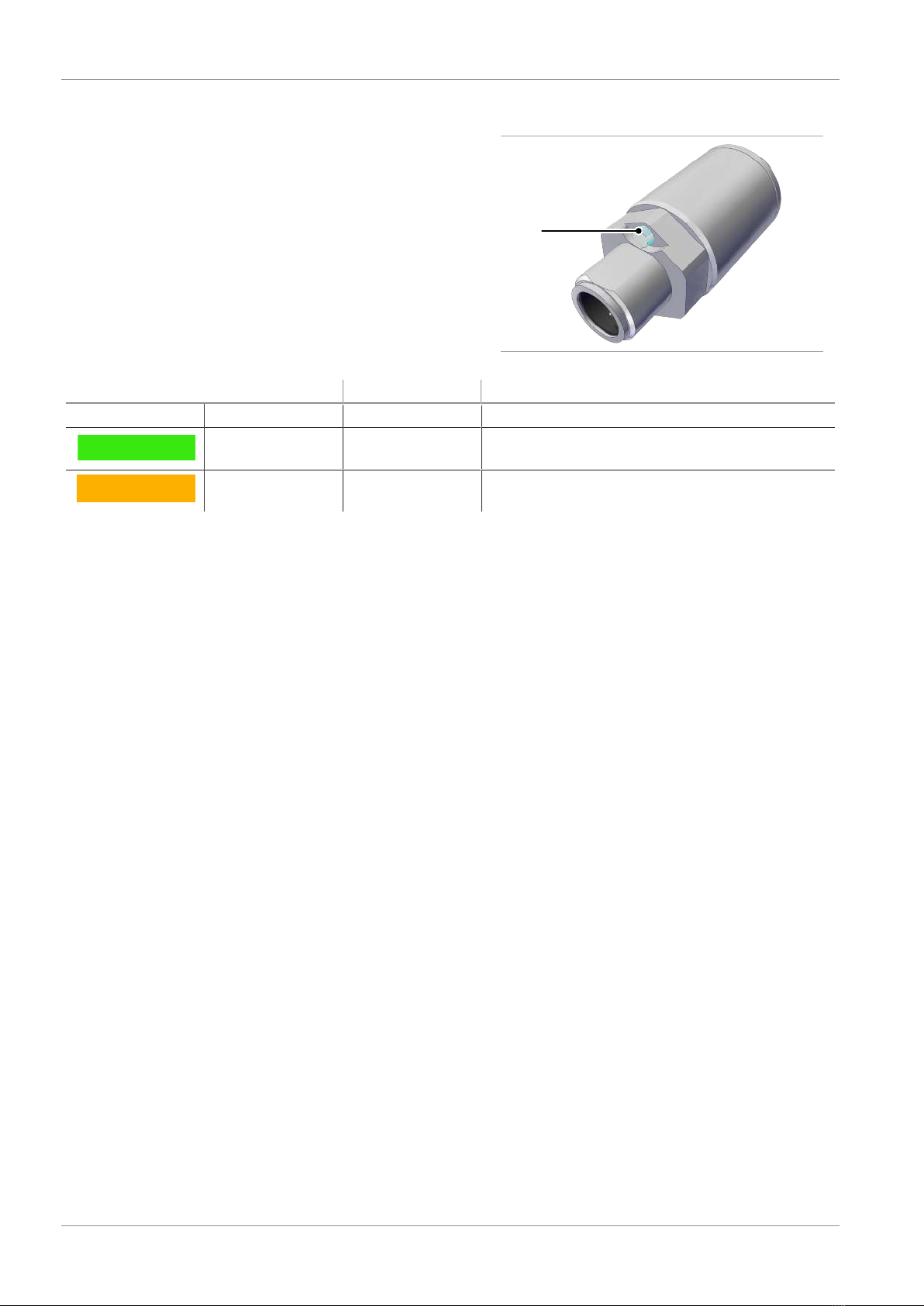
3.4 LED Status Display..............................................................................................................................10
4Technical Data...............................................................................................................................................11
4.1 General Data ...................................................................................................................................... 11
4.2 Electrical Data ....................................................................................................................................11
4.3 Mechanical Data ................................................................................................................................11
4.4 Factory Settings..................................................................................................................................12
5Installation ....................................................................................................................................................13
5.1 Mounting ...........................................................................................................................................13
5.2 Electrical Connection ......................................................................................................................... 13
6IO-Link Commissioning................................................................................................................................. 15
7Interfaces.......................................................................................................................................................16
7.1 Digital Switching Outputs (SIO) ........................................................................................................ 16
7.2 IO-Link ................................................................................................................................................16
7.3 Replacement of the Device with a Parameterization Server ..........................................................17
8Description of Functions ..............................................................................................................................18
8.1 Overview of Functions.......................................................................................................................18
8.2 Measuring Vacuum............................................................................................................................19
8.3 Monitoring the Operating Voltage .................................................................................................. 19
8.4 Switching Points.................................................................................................................................19
8.5 Teach-in for Switching Points ...........................................................................................................21
8.6 Additional Switching Point Settings.................................................................................................22
8.7 Access Rights ......................................................................................................................................22
8.8 Device Identification..........................................................................................................................23
8.9 System Monitoring and Diagnostics ................................................................................................. 24
8.10 System Commands ............................................................................................................................. 25
8.10.2 Zero-Point Adjustment (Calibration)....................................................................................25

Contents
4 / 36 EN-US · 30.30.01.03279 · 01 · 12/22
9Help with Malfunctions................................................................................................................................ 26
10 List of Error Numbers ...................................................................................................................................27
11 Cleaning the Product .................................................................................................................................... 28
12 Warranty .......................................................................................................................................................29
13 Decommissioning and Recycling .................................................................................................................30
13.1 Disposing of the Product...................................................................................................................30
13.2 Materials Used ...................................................................................................................................30
14 Accessories ....................................................................................................................................................31
15 Declarations of Conformity.......................................................................................................................... 32
15.1 EU Declaration of Conformity........................................................................................................... 32
15.2 UKCA Conformity ..............................................................................................................................33
16 VSi HD Data Dictionary 21.10.01.00121_01 2022-04-20.pdf ......................................................................34

1 Important Information
EN-US · 30.30.01.03279 · 01 · 12/22 5 / 36
1Important Information
1.1Note on Using this Document
J.SchmalzGmbH is generally referred to as Schmalz in this document.
The document contains important notes and information about the different
operating phases of the product:
• Transport, storage, start of operations and decommissioning
• Safe operation, required maintenance, rectification of any faults
The document describes the product at the time of delivery by Schmalz and is aimed at:
• Installers who are trained in handling the product and can operate and in-
stall it
• Technically trained service personnel performing the maintenance work
• Technically trained persons who work on electrical equipment
1.2The technical documentation is part of the product
1. For problem-free and safe operation, follow the instructions in the documents.
2. Keep the technical documentation in close proximity to the product. The documentation must be ac-
cessible to personnel at all times.
3. Pass on the technical documentation to subsequent users.
ðFailure to follow the instructions in these Operating instructions may result in injuries!
ðSchmalz is not liable for damage or malfunctions that result from failure to heed these instructions.
If you still have questions after reading the technical documentation, contact Schmalz Service at:
www.schmalz.com/services
1.3Type Plate
The type plate is permanently attached to the product and must always be clearly legible.
It includes the following information:
• Part number
• Part sales designation/type
• Serial number or SNR
• Coded date of manufacture
• QR code

1 Important Information
6 / 36 EN-US · 30.30.01.03279 · 01 · 12/22
1.4Symbols
This symbol indicates useful and important information.
üThis symbol represents a prerequisite that must be met prior to an operational step.
4This symbol represents an action to be performed.
ðThis symbol represents the result of an action.
Actions that consist of more than one step are numbered:
1. First action to be performed.
2. Second action to be performed.

2 Fundamental Safety Instructions
EN-US · 30.30.01.03279 · 01 · 12/22 7 / 36
2Fundamental Safety Instructions
2.1Intended use
The vacuum switch VSi HD is to be used only for measuring vacuum. For further information, see the tech-
nical data. Any other use is considered improper by the manufacturer and is deemed as contrary to the
designated use.
The product is built in accordance with the latest standards of technology and is delivered in a safe oper-
ating condition; however, hazards may arise during use.
The product is intended for industrial and commercial applications.
Intended use includes observing the technical data and the installation and operating instructions in this
manual.
2.2Non-Intended Use
Schmalz accepts no liability for damages caused by the use of the product for purposes other than those
described under "Intended Use."
Non-intended use includes the following:
• Use in potentially explosive atmospheres
2.3Personnel Qualification
Unqualified personnel cannot recognize dangers and are therefore exposed to higher risks!
The operating company must ensure the following points:
• The personnel must be commissioned for the activities described in these
operating instructions.
• The staff must be at least 18 years of age and physically and mentally capa-
ble.
• The operating staff have been instructed in the operation of the product
and have read and understood the operating instructions.
• Installation, maintenance, and repairs must be carried out only by specialists
or by persons who can prove that they have undergone appropriate train-
ing.
Applicable for Germany:
A qualified employee is defined as an employee who has received technical training and has the knowl-
edge and experience – including knowledge of applicable regulations – necessary to enable him or her to
recognize possible dangers and implement the appropriate safety measures while performing tasks. Qual-
ified employees must observe the relevant industry-specific rules and regulations.
2.4Warnings in This Document
Warnings warn against hazards that may occur when handling the product. The signal word indicates the
level of danger.
Signal word Meaning
WARNING
Indicates a medium-risk hazard that could result in death or serious injury if
not avoided.
CAUTION
Indicates a low-risk hazard that could result in minor or moderate injury if
not avoided.
NOTE
Indicates a danger that leads to property damage.

2 Fundamental Safety Instructions
8 / 36 EN-US · 30.30.01.03279 · 01 · 12/22
2.5Residual Risks
WARNING
Serious injuries due to improper mounting!
4Carry out mounting and removal only when the device is in an idle, depressurized
state.
4Use only the connectors, mounting holes and attachment materials that have been
provided.
WARNING
Uncontrolled movements of system components or falling objects caused by incor-
rect activation and switching of the Vacuum/pressure switch while persons are in
the plant (safety door opened and actuator circuit switched off)
Serious injury
4Ensure that the components are enabled via the actuator voltage by installing a poten-
tial separation between the sensor and actuator voltage.
4Wear the required personal protective equipment (PPE) when working in the danger
zone.
CAUTION
Noise pollution from leakage
Hearing damage
4Correct position.
4Wear ear protectors.
NOTE
Incorrect power supply
Destruction of the integrated electronics
4Operate the product using a power supply unit with protected extra-low voltage
(PELV).
4The system must incorporate safe electrical cut-off of the power supply in compliance
with EN60204.
4Do not connect or disconnect the connector under tension and/or when voltage is ap-
plied.
2.6Modifications to the Product
Schmalz assumes no liability for consequences of modifications over which it has no control:
1. The product must be operated only in its original condition as delivered.
2. Use only original spare parts from Schmalz.
3. The product must be operated only in perfect condition.

3 Product description
EN-US · 30.30.01.03279 · 01 · 12/22 9 / 36
3Product description
3.1General Description
The VSi-series switch can be operated in two operating modes:
• Via direct connection to discrete inputs (standard I/O = SIO) or
• Via connection through the communication line (IO-Link class A)
Switching points are indicated by LEDs.
3.2Versions
Each switch has a precise item designation (e.g. VSi-HD-V-M12-4) that is composed of the following type
key:
Type Pressure range Display Electrical connection
VSiHD V (-1 to 0bar) with LED M12-4 (1xM12, 4-pole)
3.3Design of the VSi HD
1
2
3
4
1 Fluid connector 3 M12-4 electrical connection (plug)
2 Membrane (pressure balancing for sensor) 4 Light-emitting diode (LED) status display

3 Product description
10 / 36 EN-US · 30.30.01.03279 · 01 · 12/22
3.4LED Status Display
The VSiHD has a light-emitting diode (LED) (4) for dis-
playing status information.
The table below describes the possible states on the
LED displays.
4
LED color Behavior Status
— None Off No power supply
Green Continuous
light
Operating voltage indicator
Orange Continuous
light
Indicator that switching point 1 is reached

4 Technical Data
EN-US · 30.30.01.03279 · 01 · 12/22 11 / 36
4Technical Data
4.1General Data
Operating pressure range -1 to 0bar
Accuracy ± 3% FS 1)
Resolution 1mbar
Degree of protection IP 65 (M8/M12 plugged in)
Working temperature 0to50° C
Storage temperature –10to60° C
Permitted humidity 10 to 90% RH (free from condensation)
Overpressure resistance 8bar
Measuring medium Non-aggressive gases; dry, oil-free air
Weight 22g
1) The accuracy applies to the entire measuring and temperature range.
4.2Electrical Data
Supply voltage 10 to 30VDC (PELV)1)
Power consumption (where U =
24V)
< 35mA
Current load rating per output 100 mA
Polarity reversal protection Yes, all connections
Overload/short circuit OUT1/OUT2 Automatic switch-off of both outputs
IO-Link IO-Link 1.1 Class A
Baud rate COM2 (38.4 kBits/s)
Minimum cycle time 2.3 ms
(also see separate data dictionary)
1) The power supply must correspond to the regulations in accordance with EN60204 (protected extra-low
voltage).
4.3Mechanical Data
DG1 1) G2 1) G3 L L1 LG1 SW1
19.7 1/8" exter-
nal thread
M5 inter-
nal thread
M12x1-AG 30.3 48.5 8 SW17
1) The tightening torque is 2.5Nm

4 Technical Data
12 / 36 EN-US · 30.30.01.03279 · 01 · 12/22
All dimensions given in millimeters [mm].
4.4Factory Settings
Parameter 10.06.02.00760
Switching point 1
Switching point mode and logic Normally open two-point mode (H.no)
Vacuum level switching point SP1 550mbar
Vacuum level reset point rP1 500mbar
Window hysteresis Hy1/leakage limit per sec L-1 20mbar
Switch-on delay dS1,
switch-off delay dr1
0ms
Switching point 2
Switching point mode and logic Normally open two-point mode (H.no)
Vacuum level switching point SP2 550mbar
Vacuum level reset point rP2 500mbar
Window hysteresis Hy2/leakage limit per sec L-2 20mbar
Switch-on delay dS2,
switch-off delay dr2
0ms
Transistor function PNP
IO-Link device locks, device access locks 0

5 Installation
EN-US · 30.30.01.03279 · 01 · 12/22 13 / 36
5Installation
5.1Mounting
NOTE
Exceeding the specified maximum tightening torques during mounting
Product damage
4Ensure that the specified maximum tightening torques are complied with.
1 2
3
Position Description Tightening torques
1Fluid connector 2.5 Nm
2Electrical connection (union nut) 0.8 Nm
3Electrical connection (plug) (> See ch. 5.2.1 Mounting the Con-
nection Cable,p. 13)
5.2Electrical Connection
5.2.1Mounting the Connection Cable
CAUTION
Changing output signals when the product is switched on or plug is connected
Personal injury or damage to property!
4The electrical connection must be performed only by specialists who can evaluate the
effects of signal changes on the overall system.
NOTE
Incorrect connection with the IO-Link class B port
Damage to the IO-Link master or periphery
4When operating the IO-Link class A device on an IO-Link master with a class B port, en-
sure compliant connection and potential separation.

5 Installation
14 / 36 EN-US · 30.30.01.03279 · 01 · 12/22
The switch is connected to the electrical supply using a 4-pin M12 connector Mounting.
Establish the electrical connection for the sensor as described below:
üThe connection cable with socket is provided by the customer. The maximum cable length is 30m in
SIO operation and 20m in IO-Link operation.
1. Connect the connection cable with socket at position 3.
2. Hold the socket and simultaneously attach the union nut at position 2 with a maximum tightening
torque of 0.8Nm. The plug must not twist or be subjected to any torque load (0Nm). If the plug is
subjected to torque during mounting, the torque must not exceed 0.6Nm.
5.2.2Pin Assignment of M12 Connector
M12-4 connector Pin Litz wire color Symbol Function
1 Brown USSupply voltage
2 White OUT2 Signal output 2 (SIO)
3 Blue GND Weight
4 Black OUT1 C/Q (IO-Link) and
signal output 1 (SIO)
1) When using a Schmalz connection cable (see “Accessories”)

6 IO-Link Commissioning
EN-US · 30.30.01.03279 · 01 · 12/22 15 / 36
6IO-Link Commissioning
When operating the switch in IO-Link mode (digital communication), the supply voltage, Gnd (ground)
and the C/Q communication cable must be directly connected to the corresponding connections of an IO-
Link master with IO-Link class A ports. When doing so, a new port must be used on the master for each
switch; a junction of several C/Q cables is not possible with only one IO-Link master port.
The IO-Link master must be connected in the configuration of the automation system in the same way as
other fieldbus components. To activate the port for IO-Link communication, a software tool from the re-
spective master manufacturer is usually provided (e.g. Siemens PCT, Beckhoff TwinCAT etc.).
The necessary device description data (IODD) for the switch can be downloaded from our website
www.schmalz.com.
The second output OUT2 for the vacuum switch is deactivated in IO-Link operation.

7 Interfaces
16 / 36 EN-US · 30.30.01.03279 · 01 · 12/22
7Interfaces
7.1Digital Switching Outputs (SIO)
To operate the standard digital inputs of the automation technology or to directly control the electrical
consumers, the switch has two digital outputs.
The electrical status of both of the outputs OUT1 and OUT2 thus corresponds with the logical status of
switching points 1 and 2 regardless of the switching point parameters that have been set:
• Switching point mode and switching point logic
• Switching thresholds and hysteresis (function depends on mode set)
• Switch-on and switch-off delay times
• Electrical transistor functions PNP or NPN
7.2IO-Link
The product can be operated in IO-Link mode to enable intelligent communication with a controller. The
product’s parameters can be set remotely using IO-Link mode.
The product provides many additional functions besides both switch signals via the IO-Link communica-
tion:
• The actual measurement value is provided live using the process data.
• Warnings and error statuses that occur are reported to the master via the
IO-Link event mechanism.
• More precise information regarding the system status is retrieved using the
acyclical communication channel (known as ISDU parameters).
• Within the framework of the ISDU channel, all settings (e.g. switching point
modes and delay times) for the product are read or overwritten.
• You can retrieve information about the identity of the product. The product
also provides memory for user-specific information, such as the installation
or storage location.
The following diagram shows the alignment of the 2 byte process input data for the product:
PD in
byte no.
0 1
Bit no. 15 14 13 12 11 10 9 8 7 6 5 4 3 2 1 0
Contents Measured value (14 bit) SP2 SP1
The bits SP1 and SP2 reflect the logical status of switching points 1 and 2.
The measured value is displayed as 14-bit unsigned vacuum in millibar (vacuum positive):
A detailed description of all the device parameters can be found in the data dictionary, which can be
downloaded together with the IODD as a ZIP archive from www.schmalz.com.

7 Interfaces
EN-US · 30.30.01.03279 · 01 · 12/22 17 / 36
7.3Replacement of the Device with a Parameterization Server
The IO-Link protocol provides an automated process for transferring data when a device is replaced. For
this Data storage mechanism, the IO-Link master mirrors all setting parameters for the device in a sepa-
rate non-volatile memory. When a device is swapped for a new one of the same type, the setting parame-
ters for the old device are automatically saved in the new device by the master.
üThe device is operated on a master with IO-Link revision 1.1 or higher.
üThe Data storage feature in the configuration of the IO-Link port is activated.
4Ensure that the new device is restored to the factory settings before it is connected to the IO-Link
master. If necessary, reset the device to the factory settings.
ðThe device parameters are automatically mirrored in the master when the device is configured using
an IO-Link configuration tool.
Changes to the parameters made by a PLC program using a function module are not automatically mir-
rored in the master.
4Manually mirroring data: After changing all required parameters, execute ISDU write access to the
System Command parameter (Index 2) using the Force upload of parameter data into the master
command (numerical value 0x05) (> See ch. (see Data Dictionary in the appendix)).
Use the Parameterization server function of the IO-Link master to ensure that no data is lost
when switching the device.

8 Description of Functions
18 / 36 EN-US · 30.30.01.03279 · 01 · 12/22
8Description of Functions
8.1Overview of Functions
Description Parame-
ter
See section
Switching point setting SP1/FH1
rP1/FL1
hy1/L-1
SP2/FH2
rP2/FL2
hy2/L-2
Switching Points
Switching point mode and logic Ou1
Ou2
(> See ch. 8.4.1 Switching Point Mode and Switching
Point Logic,p. 19)
Teach-in tCH Teach-in for Switching Points
Switch-on and switch-off delay dS1
dr1
dS2
dr2
(> See ch. 8.6.1 Switch-on and Switch-off Delay,p.
22)
Transistor function P-n (> See ch. 8.6.2 Transistor Function,p. 22)
IO-Link device access locks (> See ch. 8.7.2 IO-Link Device Access Locks,p. 23)
Device Access Locks
Menu PIN PIN PIN Code for Write Protection
Part number Art (> See ch. 8.8.1 Device Identity,p. 23)
Software version SoC (> See ch. 8.8.1 Device Identity,p. 23)
Serial number Sno (> See ch. 8.8.1 Device Identity,p. 23)
IO-Link identification data (> See ch. 8.8.1 Device Identity,p. 23)
User-specific identification (> See ch. 8.8.2 User-Specific Localization,p. 23)
Voltage measurement (> See ch. 8.3 Monitoring the Operating Voltage,p.
19)
Minimum and maximum values HI/LO Minimum and Maximum Values
Counter Cc1
Cc2
Ct1
Ct2
Counters
Warnings and errors Exx/FFF/-
FF
Help with Malfunctions
System status (> See ch. 8.9.3 Status Signals,p. 24)
Condition monitoring (CM) (> See ch. 8.9.4 Leakage Measurement,p. 24)
Reset to factory settings rES Reset to Factory Settings
Zero point calibration CAL Calibrating the Vacuum Sensor
Resetting HI/LO rHL Reset to Factory Settings
Reset counters rct Counters

8 Description of Functions
EN-US · 30.30.01.03279 · 01 · 12/22 19 / 36
8.2Measuring Vacuum
The VSi-HD series switch measures the vacuum relative to the ambient air pressure.
• Vacuum switch VSi-HD: The vacuum will be indicated as positive pressure
difference.
If there is excessive overpressure, an event is sent via IO-Link indicating that the measured value is outside
of the valid range.
A similar IO-Link event is sent if there is excessive vacuum.
In IO-Link operation, these cases ensure that a fixed numerical value is transmitted outside the normal
measurement range instead of a measurement value (see “Special Values” in the data dictionary). Thus
these numbers are not to be interpreted as measurement values but as notifications of overrun.
8.3Monitoring the Operating Voltage
The switch measures the amount of its operating voltage US with a resolution of 100 mV.
When the valid voltage range is left, corresponding error statuses are triggered. In the undervoltage
range, the switch delays all inputs by the user.
The product is not a voltage meter! However, the measured values and the system responses
derived from them provide a helpful diagnostics tool for condition monitoring.
8.4Switching Points
In the following, the switching point number is always denoted by an "x" when information
applies equally to both switching points. SPx therefore stands for both SP1 and SP2.
8.4.1Switching Point Mode and Switching Point Logic
Both switching points are identical in terms of function and can be parameterized independently of one
another.
There are 4 different switching point modes to choose from:
• Two-point mode H.no / H.nc
• Window mode F.no / F.nc
• Condition monitoring mode C.no / C.nc
• Diagnostics mode D.no / D.nc
In this case, there is a differentiation between the switching point logic NO (normally open) and NC (nor-
mally closed). A change in the switching point logic from NO to NC causes a logical inversion of the elec-
trical switching outputs, the switching point bits in the IO-Link process data and the orange LED display(s)
on the switch.
The condition monitoring and diagnostics modes cannot be activated simultaneously for
both switching points. That means that when a switching point is already parameterized to
C.no, C.nc, D.no or D.nc, the other can only adopt the modes H.no, H.nc, F.no or F.nc.

8 Description of Functions
20 / 36 EN-US · 30.30.01.03279 · 01 · 12/22
8.4.2Two-Point Mode
The two-point mode is a threshold switch with hysteresis.
When the measurement value increases, the switching point will be active when the switch-on threshold
SPx is reached and remains on until it falls below the reset threshold rPx. The following must always apply
for switching thresholds and reset thresholds: |SPx| > |rPx|. The hysteresis is therefore defined by the differ-
ence |SPx – rPx|.
Pressur
e p
[mbar]
Time t
Switching point
SP
Reset point rP
Output NO
Output NC
8.4.3Window Mode
In window mode, the switching point is active when the measurement value is between the upper win-
dow point FHx and the lower window point FLx. Outside this window, the switching point is inactive. If
necessary, a common switching hysteresis Hyx can be set, which symmetrically applies to both window
points. For the parameters of the upper window point FHx, lower window point FLx and hysteresis Hyx,
the following must always apply: |FHx| > |FLx| + Hyx
Pressur
e p
[mbar]
Switching point
FH
Switching point FL
Output NO
Output NC
Time
t
Hysteresis
Hysteresis
}
}
When switching from two-point mode to window mode, the current switching points SPx
and rPx are interpreted as window points FHx and FLx. They are the same internal parame-
ters (also see the data dictionary). If the resulting set of parameters are not valid in the new
mode (e.g. hysteresis too big in window mode), it is not possible to switch the mode because
the difference must be at least 30mbar.
Table of contents
Other Schmalz Switch manuals

Schmalz
Schmalz VS-P-W-D K 3C-D User manual

Schmalz
Schmalz VSi Series User manual

Schmalz
Schmalz VS-V-D-PNP User manual

Schmalz
Schmalz VS-W-D Series User manual

Schmalz
Schmalz VS W-D-K-2C Series User manual

Schmalz
Schmalz VS-V-W-D PNP K 3C-D User manual

Schmalz
Schmalz VSi-HD User manual

Schmalz
Schmalz VSi Series User manual

Schmalz
Schmalz VS-W-D-K Series User manual