manuals.online logo
Brands
  1. Home
  2. •
  3. Brands
  4. •
  5. VOLKTEK
  6. •
  7. Switch
  8. •
  9. VOLKTEK INS-8424P User manual

VOLKTEK INS-8424P User manual

-1- -2- -3-
Quick Installation Guide
1. Overview
2. Package Checklist
4. Location
5. Cabling RJ-45
3. Hardware Installation Procedure
STEP 1:
Take out the device from its packing.
STEP 2:
Attach the DIN Rail Kit or wall mount kit (optional) as picture.
The INS-8424P is an Unmanaged Industrial PoE switch
perfectly suited for extreme industrial environments and
an ideal solution to deploy in surveillance systems. The
switch is designed to meet the requirements of both
power and data transmission over single Ethernet cable
to PoE appliances and devices without the need for
power outlets, eliminating additional cost of electrical
cabling and circuits. The switch’s rugged case and
hardened components withstand high degree of
vibration, shock and wide operating temperatures from
-40oC~75oC. The INS-8424P features 4 10/100/1000Base-T
ports and 2 Gigabit SFP slot to satisfy new and evolving
network demands. With 4 IEEE 802.3af/at compliant
ports, the switch provides up to 30W per port to meet
the growing demand of higher power consuming
network devices such as wireless access points, IP
cameras, and other powered devices (PDs).
Before installing INS-8424P, verify that the package
contains the following items:
 INS-8424P Switch x 1
 DIN Rail Kit x 1
Quick Installation Guide x 1
STEP 3:
Connect 48VDC Power Adapter to mini-DIN or
connect 48~57VDC power to terminal block.
STEP 4:
Connect the Ethernet (RJ-45) port to the networking
device. See the LNK/ACT LED to conrm that the
connection is established.
The INS-8424P can be DIN-Rail-mounted in cabinet or
enclosure.
DIN-Rail-mounted with INS-8424P
Mounting the Switch Removing the Switch
The RJ-45 ports on the INS-8424P support auto negotia-
tion and auto MDI/MDI-X. This feature eliminates the
worry of using specic cable types.
Category 5e cable or above should be used
INS-8424P
DIP Switches
Power Input
mini-DIN
Power Input
Terminal Block
Grounding
Screw
Reset
DIN Rail Kit
6. Redundant Power Inputs
Turn the power o before connecting modules
or wires. The correct power supply voltage is listed on
the product label. Check the voltage of your power
source to make sure that you are using the correct
voltage. Do NOT use a voltage greater than what is
specied on the product label.
Safety rst
!
Calculate the maximum possible current in each
power wire and common wire. Observe all electrical
codes dictating the maximum current allowable for
each wire size. If current go above the maximum
ratings, the wiring could overheat, causing serious
damage to your equipment.
-4- -5- -6-
PWR
RPS
7. LED Indicators
ON: Master power alarm reporting is enabled
OFF: Master power alarm reporting is disabled
ON: Redundant power alarm reporting is enabled
OFF: Redundant power alarm reporting is disabled
Illuminated
O
10/100/
1000
Mbps
(Green)
Illuminated Copper ports speed at 1000Mbps
O Copper ports speed at
10/100Mbps
LNK/
ACT
(Green)
Illuminated
Blinking
O
Illuminated
O
Illuminated
O
You can use either “mini-DIN” or “Terminal Block
(PWR)” for primary power and “Terminal Block (RPS)”
for secondary power source, to be a Redundant Power
Input. Top views of mini-DIN and Terminal Block are
shown as picture.
Redundant Power Input: Choose either “mini-DIN”
or “Terminal Block (PWR)” as primary power. If you
choose “Terminal Block (PWR)”, please refer to
option 1, unless follow option 2.
Insert the “mini-DIN” connector into “mini-DIN”
receiver and “Terminal Block (RPS)” into terminal
block receptor.
6.1. Wiring the Redundant Power Inputs
Option 2:
Insert the terminal block connector which includes
“PWR” and “RPS” into the terminal block receptor.
Option 1:
6.2. DIP Switch Setting
PWR
RPS
PWR
(Green)
RPS
(Green)
ALM
(Red )
Power lost alarm
No power lost or DIP function
is disabled
Ethernet link-up
Activity (receiving or transmitting data)
Port disconnected or link failed
Illuminated
Blinking
O
SFP
5th~6th
port
(Green)
Ethernet link-up
Activity (receiving or transmitting data)
port disconnected or link failed
PoE
1st~4th
port
(Green)
Illuminated
O
PoE power is delivered to the PD
device
No outgoing PoE power
Power ON from 48VDC power
adapter or terminal block
Power O
Power ON from 48VDC terminal block
Power O or failure
mini-DIN Terminal Block
v1.0
6400-000140
LIMITED WARRANTY
Turn the power o before connecting modules
or wires. The correct power supply voltage is listed on
the product label. Check the voltage of your power
source to make sure that you are using the correct
voltage. Do NOT use a voltage greater than what is
specied on the product label.
Calculate the maximum possible current in each
power wire and common wire. Observe all electrical
codes dictating the maximum current allowable for
each wire size. If current go above the maximum
ratings, the wiring could overheat, causing serious
damage to your equipment.
!ATTENTION:
Please use a power supply from 48~57VDC, the device
power shall be supplied by SELV circuit.
!ATTENTION
We strongly request that each Industrial PoE switch to
connect to individual power supply. Please don’t use one
power supply to two or more PoE switches at a time.
48~57VDC
VOLKTEK Corporation warrants this product against
defect in materials and workmanship for a period of Five
(5) YEARS to the original purchaser.
If you discover a defect, VOLKTEK will, at its sole option,
repair or replace the product at no additional charge,
provided that you contact VOLKTEK technical support to
obtain a Return Merchandise Authorization Number
(RMA) and instruction on how and where repairs can be
made. This warranty does not apply if the product has
been damaged by accident, abuse, misuse, misapplication,
neglect, re, water, lightning or other acts of nature,
failure to follow supplied instructions, installation or
removal, have been repaired or have undergone
attempted repair by unauthorized personnel without
written consent from VOLKTEK, modied, defaced, or has
its serial numbers removed. VOLKTEK reserves the right
to use remanufactured, refurbished, or used parts and
components in making warranty repairs.
All expressed or implied warranties for this product,
including the implied warranties of merchantability and
tness for a particular purpose are limited in duration to
the warranty period. No warranties expressed or implied
will applied after this period. VOLKTEK shall not be liable
for lost prots, damage to other property caused by any
defects of this product, or damages based upon
inconvenience, loss of product use, loss of time,
commercial use, incidental and/or consequential damages
for the breach of any expressed or implied warranty,
including damages to property, and to the extent permitted
by law, damages for personal injury, even if VOLKTEK has
been advised of the responsibilities of such damages.
If you have any further questions, please contact Customer
Support:
Address of the manufacturer.
VOLKTEK CORPORATION
4F, 192 Liancheng Rd, Zhonghe, New Taipei 23553, Taiwan
Email: [email protected]
Tel: +886-2-8242-1000
Fax: +886-2-8242-3333
Other VOLKTEK Switch manuals

VOLKTEK NSH-5509 User manual

VOLKTEK

VOLKTEK NSH-5509 User manual

VOLKTEK NSH-9308P User manual

VOLKTEK

VOLKTEK NSH-9308P User manual

VOLKTEK INS-802 User manual

VOLKTEK

VOLKTEK INS-802 User manual

VOLKTEK INS-806 User manual

VOLKTEK

VOLKTEK INS-806 User manual

VOLKTEK IEN-8428P-24V User manual

VOLKTEK

VOLKTEK IEN-8428P-24V User manual

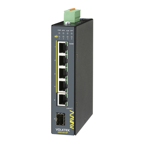
VOLKTEK HNS-8415P User manual

VOLKTEK

VOLKTEK HNS-8415P User manual

VOLKTEK NSH-2926 User manual

VOLKTEK

VOLKTEK NSH-2926 User manual

VOLKTEK NSH-9309 User manual

VOLKTEK

VOLKTEK NSH-9309 User manual

VOLKTEK INS-801W User manual

VOLKTEK

VOLKTEK INS-801W User manual

VOLKTEK NSH-5632 User manual

VOLKTEK

VOLKTEK NSH-5632 User manual

Popular Switch manuals by other brands

iNels RFSAI-62B quick start guide

iNels

iNels RFSAI-62B quick start guide

Ihse Draco MultiView 4K60 MV42 Series user manual

Ihse

Ihse Draco MultiView 4K60 MV42 Series user manual

Linkskey LKU-S02ASK Quick installation guide

Linkskey

Linkskey LKU-S02ASK Quick installation guide

Quark-Elec QK-R043 manual

Quark-Elec

Quark-Elec QK-R043 manual

NETGEAR M4350 Series Hardware installation guide

NETGEAR

NETGEAR M4350 Series Hardware installation guide

Intel True Scale Fabric 12000 Series user guide

Intel

Intel True Scale Fabric 12000 Series user guide

Berker 8510 51 00 Operation instructions

Berker

Berker 8510 51 00 Operation instructions

Cisco RSP2 - Route Switch Processor 2 Installation and configuration guide

Cisco

Cisco RSP2 - Route Switch Processor 2 Installation and configuration guide

Wintal HT-6100 instruction manual

Wintal

Wintal HT-6100 instruction manual

Sony HKS-5810M Operation manual

Sony

Sony HKS-5810M Operation manual

HRT One SRE user guide

HRT

HRT One SRE user guide

CAMBRIONIX PowerPad15C user manual

CAMBRIONIX

CAMBRIONIX PowerPad15C user manual

steute RF 96 ST SW868 Mounting and wiring instructions

steute

steute RF 96 ST SW868 Mounting and wiring instructions

Dell Networking S5000 installation guide

Dell

Dell Networking S5000 installation guide

Lantech IPES-0204DFT-4 user manual

Lantech

Lantech IPES-0204DFT-4 user manual

Cisco Catalyst 3030 Getting started guide

Cisco

Cisco Catalyst 3030 Getting started guide

Cisco IE 2000 Release notes

Cisco

Cisco IE 2000 Release notes

Watlow E-Safe II Specifications

Watlow

Watlow E-Safe II Specifications

manuals.online logo
manuals.online logoBrands
  • About & Mission
  • Contact us
  • Privacy Policy
  • Terms and Conditions

Copyright 2025 Manuals.Online. All Rights Reserved.