3
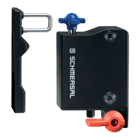
AZ201
Operating instructions
Safety switch
EN
2.5 Technical data
Standards: IEC 60947-5-1, IEC 60947-5-3,
ISO 13849-1, IEC 61508, IEC 62061
Material of the enclosure: glass-fibre reinforced thermoplastic,
self-extinguishing
Active principle: RFID
Frequency band: 125 kHz
Transmitter output: max. -6 dBm
Coding level according to ISO 14119:
- I1-version: high
- I2-version: high
- Standard coding version: low
Reaction time:
- Actuator: ≤ 100 ms
- Inputs: ≤ 0.5 ms
Duration of risk: < 200 ms
Time to readiness: < 4000 ms
Actuator: AZ/AZM201-B1, AZ/AZM201-B30
Series-wiring: Unlimited number of components,
please observe external cable protection,
max. 31 components in case of serial diagnostics
Length of sensor chain: max. 200 m
(cable length and cable section
alter the voltage drop depending
on the output current)
Mechanical data
Termination: Screw terminals or cage clamps,
Connector plug M12
Cable section: min. 0.25 mm², max. 1.5 mm²
(including conductor ferrules)
Cable entry: M20
Mechanical life: ≥ 1,000,000 operations
Actuating speed: max. 0.2 m / s
Tightening torque for the cover screws: 0.7 ... 1 Nm (Torx T10)
Latching force: 30 N
Switching distances to IEC 60947-5-3
Assured switching distance sao:4.0 mm
Assured switch-off distance sar:30 mm
Hysteresis: max. 1.5 mm
Repeat accuracy: < 0.5 mm
Switching frequency: 1 Hz
Ambient conditions
Ambient temperature: −25 °C ... +70 °C
Storage and transport temperature: −25 °C ... +85 °C
Protection class: IP66, IP67 to IEC 60529
Protection class: III
Resistance to shock: 30 g / 11 ms
Resistance to vibration: 10 ... 55 Hz, amplitude 1 mm
Insulation values to IEC/EN 60664-1:
- Rated insulation voltage Ui: 32 VDC
- Rated impulse withstand voltage Uimp: 0.8 kV
- Over-voltage category: III
- Degree of pollution: 3
Electrical data
Operating voltage UB: 24 VDC - 15% / +10%
(stabilised PELV power supply)
Power consumption device: 0.7 A
Required rated short-circuit current: 100 A
No-load current Io:max. 0.5 A
External device fuse rating:
- Screw terminals or cage clamps: ≤ 4 A when used
in accordance with UL 508;
- Connector plug M12: ≤ 2 A
Electrical data – Safety inputs
Safety inputs: X1 and X2
Switching thresholds: − 3 V … 5 V (Low), 15 V … 30 V (High)
Power consumption per input: typically 2 mA / 24 V
Accepted test pulse duration on input signal: ≤ 1.0 ms
- With test pulse interval of: ≥ 100 ms
Test pulse interval: 1000 ms
ZVEI classification:
Countersink: C1 Source: C1 C2 C3
Electrical data – Safety outputs
Safety outputs: Y1 and Y2
Switching elements: p-type, short-circuit proof
Utilisation category: DC-13: Ue/Ie: 24 VDC / 0.25 A
Rated operating current Ie:0.25 A
Leakage current Ir: ≤ 0.5 mA
Voltage drop Ud: ≤ 4 V
Cross-wire monitoring by device: Yes
Test pulse duration: ≤ 0.5 ms
Test pulse interval: 1000 ms
ZVEI classification:
Source: C2 Countersink: C1 C2
Electrical data – Diagnostic output
Diagnostic output: OUT
Switching element: p-type, short-circuit proof
Utilisation category: DC-13: Ue/Ie: 24 VDC / 0.05 A
Rated operating current Ie: 0.05 A
Voltage drop Ud:≤ 4 V
Serial diagnostic SD
Operating current: 0.15 A
Wiring capacitance: max. 50 nF
LED status display
green LED: Supply voltage
yellow LED: Device condition
red LED: Internal device error
Use isolated power supply only.
For use in NFPA 79 Applications only.
Adapters providing field wiring means are available from
the manufacturer. Refer to manufacturers information.
2.6 Safety classification
Standards: ISO 13849-1, IEC 61508, IEC 62061
PL: e
Control Category: 4
PFH value: 1.9 x 10⁻⁹ / h
PFD: 1.6 x 10⁻⁴
SIL: suitable for SIL 3 applications
Service life: 20 years
