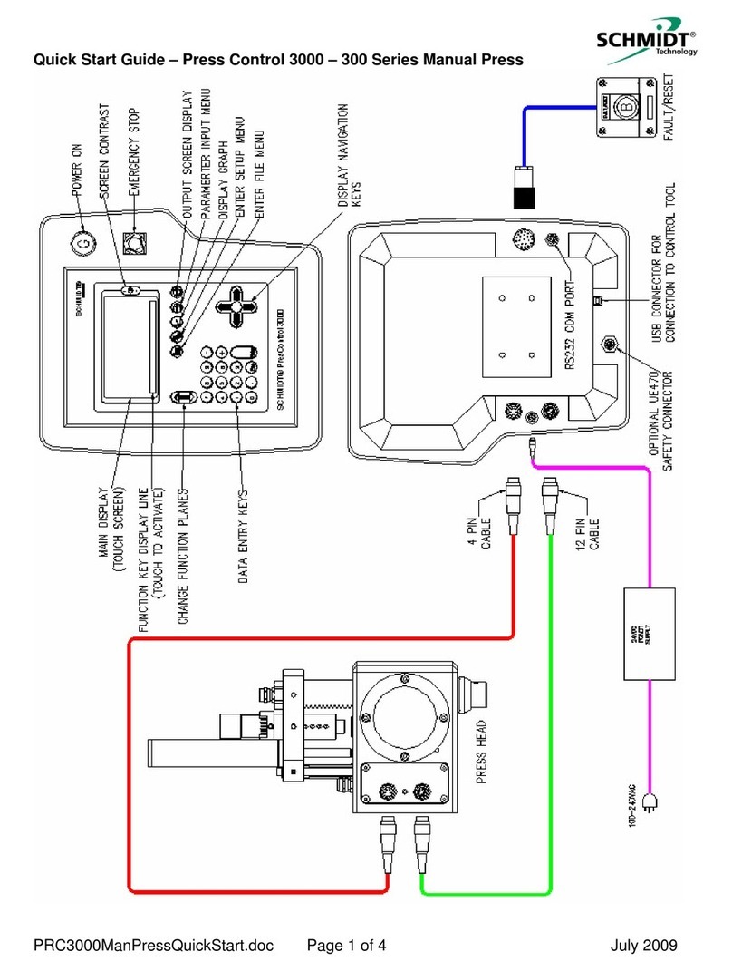
Schmidt PressControl 3000 User manual

Operator’s manual
SCHMIDT®PressControl 3000
SCHMIDT®press system with force/stroke-monitoring and
SCHMIDT®PressControl 3000

General
SCHMIDT®PressControl 3000 – V1.3
2
0. General
Contact adresses
SCHMIDT Technology GmbH
Feldbergstr. 1
D-78112 St. Georgen
Tel. +49 (7724) 899-0
Fax. +49 (7724) 899-101
eMail info@schmidttechnology.de
www.schmidttechnology.de
SCHMIDT Technology Corp.
Cranberry Corporate Center
280 Executive Drive
USA-Cranberry Twp., PA 16066
Tel. +1 (724) 772-46 00
Tel. +1 (800) 959-12 18
Fax. +1 (724) 772-46 88
eMail info@schmidtpresses.com
www.schmidtpresses.com
SCHMIDT Technology Ltd
Unit 14/18 The Markham Centre
UK-Theale, Reading
Berks RG7 4PE
Tel. +44 (118) 9305-464
Fax. +44 (118) 9305-440
eMail sales@schmidttechnology.co.uk
www.schmidttechnology.co.uk
SCHMIDT Technology GmbH
Niederlassung Schweiz
Gerbeackerstr. 8
CH-3210 Kerzers
Tel. +41 (0)31 755 40 71
Fax. +41 (0)31 755 40 73
eMail infoCH@schmidttechnology.ch
www.schmidttechnology.ch
©2007 SCHMIDT Technology GmbH
All rights reserved. Printed in the Federal Republic of Germany.
Version and revision date:
Version 1.3 of August 2007
Germany
USA
Great
Britain
Switzerland

General
SCHMIDT®PressControl 3000 – V1.3 3
Table of Contents
Documentation structure.................................................................................5
1Safety.................................................................6
1.1 Designated use.....................................................................................6
1.2 Organisational measures of the system operator.................................7
1.3 Risks .....................................................................................................7
1.4 Safety devices.......................................................................................8
Operational status indicator..................................................................8
Emergency Stop pushbutton.................................................................8
2PressControl 3000.............................................9
2.1 Function ................................................................................................9
2.2 Technical Data....................................................................................10
3Assembly and startup.....................................11
3.1 Transport and storage.........................................................................11
3.2 Connecting the control unit.................................................................12
3.3 Installing the control unit.....................................................................12
4Operation......................................................... 14
4.1 Operating elements.............................................................................14
4.2 User interface......................................................................................14
System functions.................................................................................14
Softkeys and operating levels.............................................................15
4.3 Switching on and off............................................................................16
4.4 Reference run .....................................................................................16
5Data Input ........................................................18
5.1 Default settings ...................................................................................18
5.2 Standard parameters overview...........................................................22
6Text and system outputs................................24
6.1 System outputs ...................................................................................24
6.2 Process data.......................................................................................24
7Press processes..............................................25
7.1 Defining the press process .................................................................25
Press parameters................................................................................25
Return stroke criterion.........................................................................25
Stroke takeover (only two-hand control).............................................26
7.2 Optimisation of the press process ......................................................27
Bend-Up (Yield Factor).......................................................................27

General
SCHMIDT®PressControl 3000 – V1.3
4
Idle-stroke monitoring......................................................................... 30
Block limit window.............................................................................. 31
7.3 Acknowledging an incorrect pressing .................................................32
Acknowledging by means of external luminous button...................... 32
Acknowledging by means of the reject box........................................ 33
7.4 Counter................................................................................................33
Piece counter ..................................................................................... 33
Pre-selection counter ......................................................................... 34
8Further integrated functions ..........................36
8.1 Setup mode for tool change................................................................36
8.2 Operation with ControlTool .................................................................36
8.3 Taring the force value .........................................................................38
8.4 Parts inquiry ........................................................................................38
9Dataset management ......................................40
9.1 Principle of the dataset management .................................................40
9.2 Managing multiple datasets ................................................................41
Creating and storing datasets............................................................ 41
Load dataset....................................................................................... 41
Renaming dataset.............................................................................. 42
10 Quality monitoring ..........................................43
10.1 Curves.................................................................................................43
Curve display...................................................................................... 43
Enlarging details................................................................................. 44
10.2 Tolerances...........................................................................................45
Reference data................................................................................... 45
Force tolerances ................................................................................ 46
Stroke tolerances ............................................................................... 47
Managing tolerances.......................................................................... 48
Move tolerance data........................................................................... 49
11 Maintenance and servicing.............................51
11.1 Setting the force offset........................................................................51
11.2 Calibrating the force sensor................................................................52
11.3 Adjusting the stroke offset...................................................................54
12 Customer Service............................................56

General
SCHMIDT®PressControl 3000 – V1.3 5
Optional
Documentation structure
The operator’s manual for the press system is divided into the following
documentation modules:
Operator's Manual –SCHMIDT®Press
•Structure and function
•Assembly and startup
•Maintenance and servicing
Operator's Manual –SCHMIDT®SafetyModule
•Structure and function
•Mounting and startup
•Maintenance and servicing
Operator's Manual –SCHMIDT®PressControl 3000
•Structure and function
•Assembly and startup
•User interface
•Practical operation
•Maintenance and servicing
Technical documentation – SCHMIDT®press system
•Circuit diagram and pneumatic plan
•Manufacturer’s Declaration or Declaration of Conformity
•Spare part lists
•Test certificates
•Description of special functions
User Manual –SCHMIDT®ControlTool - Teil 1
•Installation
•User interface
•Project and dataset management
•Quality monitoring
•Update and service
User Manual – SCHMIDT®ControlTool - Teil 2
•Fundamentals
•PLC programming
•Range of commands
User Manual –SCHMIDT®SPC
•Structure and function
•User interface
•Practical operation
Optional
Optional

1 Safety
SCHMIDT®PressControl 3000 – V1.3
6
1 Safety
The press system has been built, manufactured and tested ex works for its
function and safety in accordance with current safety regulations and state-
of-the-art methods. This guarantees its operational safety. Nevertheless the
press system can involve risks, if
•it is not used in accordance with its designated use,
•it is operated by untrained personnel,
•it is modified or converted incorrectly or
•the safety regulations are not observed.
The press system may only be used if it is in technically perfect condition. All
required safety devices must be in place and fully functional.
Apart from the instructions listed in this operating manual, the current
country-specific safety and accident prevention regulations provided by law
apply.
1.1 Designated use
The control unit may be operated on a SCHMIDT PneumaticPress or a
SCHMIDT HydroPneumatic Press only in connection with the SCHMIDT
SafetyModule.
The control unit may only be used, together with the above mentioned
components, for the following press processes:
•Assembling
•Riveting
•Crimping
•Bonding
•Forming
•Pressing
•Flaring
•Punching
Using the system for purposes other than those described above is contrary
to the designated use. The manufacturer cannot be held liable for any
damage resulting from such a use. The risk lies entirely with the user.
Do not make any changes to the press system which could impair safety.
The manufacturer cannot be held liable for any damage resulting from such
a use. The risk lies entirely with the user.
Designated use also includes:
•compliance with the documentation
•compliance with the inspection and maintenance measures

1 Safety
SCHMIDT®PressControl 3000 – V1.3 7
1.2 Organisational measures of the system
operator
Use as safety component
If the control has been delivered not ready for use (with a Declaration of
Conformity according to Annex II b of the Machinery Directive 98/37/EC) the
operator or the system manufacturer must ensure observance of the safety
regulations.
Of the safety regulations, observe in particular the Machinery Directive
98/37/EC and the standards DIN EN 349, DIN EN 292 and DIN EN 294.
The operator must make sure that
•the instructions contained in the operating manual concerning
startup, operation and maintenance are observed.
•the press system is properly operated, tested and maintained and
the responsibilities for these tasks are clearly set out.
•those persons responsible for activities on the press system have
read this operating manual and, in particular, chapter “1 Safety”,
before starting work. This also applies to persons who work only
occasionally.
•this operating manual is always kept within easy reach at the
workplace.
1.3 Risks
The press system is constructed so as not to put any persons at risk when
used in accordance with its designated use. However, certain parts of the
press system cannot be protected without limiting its functionality and
usability. Thus, despite constructional safety measures, a residual danger
remains.
Safe press operation requires the interaction of press, control unit, tools,
safety devices and conduct of the user in accordance with the safety
measures.
Injuries or death caused by touching live parts
During assembly and repair work you may come into contact with parts
which carry dangerous voltage in operation. Touching live parts may cause
death.
Any work on the electrical system or equipment must be carried out
only by trained electricians or by specially instructed persons under the
control and supervision of a trained electrician and in accordance with
the applicable electrical engineering rules and regulations.
DANGER
!
DANGER
!

1 Safety
SCHMIDT®PressControl 3000 – V1.3
8
1.4 Safety devices
Figure 1-1: PressControl 3000
1 Operational status indicator 2 EMERGENCY STOP pushbutton
Operational status indicator
The operational status indicator is located on the display of the control unit.
The status indicator is lit in green permanently when the press system has
been switched on and is ready for operation.
Emergency Stop pushbutton
There is an EMERGENCY STOP pushbutton on the control panel of the
control unit.
Press the Emergency Stop pushbutton immediately in case of
emergency.
The press system is taken to a safe operating state. All moving
machines are stopped immediately and the press system is
depressurised.
Eliminate the error.
Unlock the Emergency Stop pushbutton by turning and pulling it.
Switch the press system on again at the control unit.
1
2
What to do in an
emergency
Start af
ter Emergency
Stop

2 PressControl 3000
SCHMIDT®PressControl 3000 – V1.3 9
2 PressControl 3000
2.1 Function
The SCHMIDT®Press System with force/stroke monitoring and SCHMIDT®
PressControl 3000 operates according to the following principle:
The sequence control of the press process is done via a PLC program. The
PLC program carries out the following functions:
•Control of the process data acquisition sequence
•Monitoring of the press process on the basis of the set quality
parameters
•Plain text output on the display.
Additional functions (e.g. feeds, workpiece detection, sorting of OK and Not
OK parts, etc.) are effected via the PLC program.
Figure 2-1: Block circuit diagram
Sequence control

2 PressControl 3000
SCHMIDT®PressControl 3000 – V1.3
10
2.2 Technical Data
Figure 2-2: Dimensions of the control unit
Technical Data
Display Liquid crystal display (128 x 240 pixels) with
background illumination, 16 lines of 40 columns
each, with touch screen functions
Keypad Touch screen
Interfaces USB
Mains connection 100 up to V AC / 50 up to 60 Hz max. back-up
fuse 16 A
Supply voltage 24 V DC
Current consumption 350 mA / 230 V or
700 mA / 110 V or
2.5 A / 24 V
Weight 5.5 kg incl. external power supply unit
Ambient temperature 0 up to 40° C
Air humidity up to max. 95% relative, non condensing
Protection type IP 54
Dimensions
~ 290
~ 320
~ 80

3 Assembly and startup
SCHMIDT®PressControl 3000 – V1.3 11
3 Assembly and startup
Safety instructions
The control unit may only be installed and serviced by setup engineers
who have been commissioned and trained by the company.
Any work on the electrical equipment of the press must be carried out
only by trained electricians or by specially instructed persons under the
control and supervision of a trained electrician and in accordance with
the applicable electrical engineering rules and regulations.
Check the control unit, accessories and all supply lines for possible
damage prior to each startup.
Switch off a defective press immediately or depressurise the pneumatic
system immediately and have the malfunctions repaired as soon as
possible.
3.1 Transport and storage
Check the delivered press system components for visible transport
damage.
Report any transport damage immediately to the following authorities:
- the forwarding agent
- the dispatch department of SCHMIDT Technology.
Keep the original packaging for later transport and/or for further storage.
Use the original packaging for further transport (service, repairs….).
Ensure proper packaging of the components.
Ensure proper packaging of the components, if they must remain
unused for longer periods.
Store the control unit in upright position (do not place on the display)
Store the control unit in such a way that it is not subject to large
fluctuations in temperature. Otherwise, the resulting condensed
moisture may cause corrosion on critical press or control unit
components.
Please observe the information on the ambient conditions in chapter
"2.2 Technical Data".
CAUTION
!
Delivery
Transport
Storage

3 Assembly and startup
SCHMIDT®PressControl 3000 – V1.3
12
3.2 Connecting the control unit
The back of the control unit housing contains the following connections:
Figure 3-1: Connections
1 not used (only ManualPress) 5 Inputs/outputs
2 Supply voltage 6 Service
3 Force/stroke sensors 7 USB
4 CAN
Damage to the force/stroke sensors
The cables may only be connected in the de-energized state. This applies
especially to the connection of the force/stroke sensors.
Connect the control unit in the order described below.
The communication between the control unit and the press or the
force/stroke sensors takes place via two connections.
Connect the control unit to the press using the cable for the force/stroke
sensors (12-pin plug).
Connect the control unit to the SafetyModule using the CAN-cable (5-
pin plug).
Connect the control unit to the 24V power supply of the SafetyModule.
3.3 Installing the control unit
The control unit is equipped ex works with a control unit holder for table or
wall mounting.
Insert the control unit in the table holder.
Tighten the fastening screw (1).
2
1
3
4
5
6
7
CAUTION
!
Communication
Power supply

3 Assembly and startup
SCHMIDT®PressControl 3000 – V1.3 13
Figure 3-2: Control unit holder
1 Fastening screw (hidden in the figure)
2 Screw for inclination adjustment (on both sides)
The holder adapter in the control unit must not be removed.
The holder allows the control unit to be swivelled by 70°.
Loosen the screw connections for the inclination adjustment (2).
Set the desired control unit inclination.
Tighten the screw connections for the inclination adjustment (2) again.
1
2
Setting the inclination

4 Operation
SCHMIDT®PressControl 3000 – V1.3
14
4 Operation
4.1 Operating elements
The SCHMIDT®PressControl 3000 press system is basically operated by
means of the following operating elements:
Figure 4-1: Operating elements
1 LCD with touch screen 6 On/Off pushbutton
2 “Set contrast” key 7 EMERGENCY STOP pushbutton
3 Softkeys 8 System function keys
4 “Change operating level” key 9 Cursor keys
5 Numeric keys 10 "Acknowledge incorrect pressing" key.
4.2 User interface
System functions
Using the system function keys you can directly access the most important
display modes having system functions.
Figure 4-1: System function keys
1 Datasets 4 Data Input
2 System Options 5 Data Output
3 Curve Output
In this display mode, you have access to the commands for dataset
management. They include commands for creating, saving, renaming and
loading datasets.
1 2 3 4 5
6
7
8
9
5
4
2
1
10
3
Datasets

4 Operation
SCHMIDT®PressControl 3000 – V1.3 15
Changing
operating level
In this display mode, you have access to the commands for the system
settings of the control. They include settings for time, date, alarms, machine
parameters, interface definitions, etc.
In this display mode, you have access to the commands for displaying the
recorded curve. They include commands for zooming, tolerance data input,
and for displaying the curve.
In this display mode, you have access to the machine parameters for
operating the press system. They include parameters for the return stroke,
for process data acquisition, or for quantities.
In this display mode, the operator can view information on the state of the
press system. This information includes data on the system condition,
quantities, incorrect pressings, etc.
You can find detailed information concerning the most important menu
commands in the following chapters.
Softkeys and operating levels
The SCHMIDT®PressControl 3000 press system is provided with a PLC
program having a large number of basic functions. They can be activated by
means of softkeys on the touch screen.
The following table describes the softkeys included in the standard PLC
program.
Operating level Softkey Description
1 CtrON Switch on control unit
CtrOFF Switch off control unit
Servic
“Setup” operating mode (switch press to airless mode).
2 PCTon Switch pre-selection counter on
PCToff Switch pre-selection counter off
PCT-0- Set pre-selection counter to zero
CNT-0- Set piece counter to zero
ACK Acknowledge fault
3 Ref. Carry out a reference run
The control starts automatically with operating level “1”.
Press the "Change operating level" key (see Figure 4-1). This is how
you switch to the next higher/lower operating level.
All softkeys labelled with asterisk have not been assigned. The assignment
of the softkeys and their allocation to an operating level is done by the PLC
program. For further information concerning the programming of additional
softkeys, please see the "User Manual - SCHMIDT®ControlTool - Part 2".
System Options
Curve Output
Data Input
Data Output
Softkeys

4 Operation
SCHMIDT®PressControl 3000 – V1.3
16
4.3 Switching on and off
After all mounting and installation tasks are complete, the press system can
be started.
As the control unit is supplied with voltage from the SafetyModule, it can also
be switched on or off by means of the main switch of the SafetyModule.
Start the press system as described in chapter “3.4 Switching on and
off” in the "Operating Manual – SCHMIDT®SafetyModule".
Servic......CtrOFFCtrON1
Control Off!
PC-DEAC
Dataset 1 ( )
1
Figure 4-3: Display after the self-test
Change to operating level 1.
Select the “CtrON” softkey.
The system first carries out a self-test and then automatically starts the
delivered PLC program. After the system has been switched on, the
status indicator is lit and the message “Machine ok” appears on the
display.
4.4 Reference run
After switching on the control unit, a reference run must be carried out. This
is shown by the “Operate press <Ref>” message on the display.
Servic......CtrOFFCtrON1
Operate press <Ref>
Machine ok.
PC-DEAC
Dataset 1 ( )
1
Figure 4-4: Display after switching on

4 Operation
SCHMIDT®PressControl 3000 – V1.3 17
Carry out a working stroke. After reaching the reference point, the press
moves automatically to the TDC position.
Servic......CtrOFFCtrON1
.000 mm
0 N
Reached stroke :
Reached force :
0 pcs
0 pcs
0 pcs
Quantity :
Quantity nok :
Quantity ok :
30.000 mmReturnstroke at stroke:
2-Hand-Release
Machine ok.
PC-DEAC
Dataset 1 ( )
1
Figure 4-5: Display after the reference run
In general you can always carry out a reference run manually. During this
operation the control unit must not be switched off.
Change to operating level 3.
Select the “Ref” softkey.
Perform the reference run, as described above.
Manual reference run

5 Data Input
SCHMIDT®PressControl 3000 – V1.3
18
5 Data Input
Various parameters (data input, system options, etc.) can be input directly at
the control unit.
Select the "Data Input" system function key.
1 CtrON CtrOFF ... ... Servic
3.0 sec
3.0 sec
20
1
5.000 mm
2.0 sec
30.000 mm
20.000 mm
1500 N
1
9 BDC-stroketakeover
8 Alarmtime press error
7 Alarmtime quan. reached
6 Target count
5 Counter access
4 Start/Stop PDA
3 Returnstroke Time
2 Returnstroke Stroke
1 Returnstroke Force
0 Mode : F=0,s=1,t=2,m=3
Input Dataset 1
Figure 5-1: Data input
Mark the desired parameter. The selected line is given a dark
background.
Press the "Enter” key. The previously set value is deleted and the
cursor blinks at the input position.
Enter the desired value using the numeric keys. Input errors can be
corrected by means of the "Left" cursor key.
Confirm the entry by pressing the “Enter” key.
10 input parameters can be displayed simultaneously on the display of the
control unit. You can move from one parameter to the next by using the “Up”
/ “Down” cursor keys. With the "Left" and "Right" cursor keys, you can jump
from on block of 10 to the next.
5.1 Default settings
Contrast
The display is blank
With increasing operating temperature, the contrast of the display
diminishes. Since nothing can be seen any longer on the display, the user
may think that the control is defective.
Check if the contrast is set correctly using the "Contrast setting" key.
Calling data input
Scrolling
CAUTION
!

5 Data Input
SCHMIDT®PressControl 3000 – V1.3 19
Figure 5-1: "Contrast setting" keys
1 "Contrast setting" keys
Machine parameters
Wrong evaluation of the quality parameters
The sensitivity of the sensors of the connected press is set by the machine
parameters. The set parameters have been tested and should only be
changed by experts.
Select the "System Options" system function key.
In the "System Options" submenu, select the "Machine Parameter"
selection.
1 CtrON CtrOFF ... ... Servic
Graphic init 10Maximum Force [kN] 400Res. Force Sensor [I/kN] 100Max. Stroke [mm] 2000Res. Stroke Sensor [I/mm*10]
Machine Parameter
Figure 5-3: Machine parameters
Modify the corresponding parameters according to the sensor type.
Parameter 5 kN 20 kN 100 kN 160 kN
Res. Stroke Sensor 2000 2000 2000 2000
Max. Stroke 100 100 100 100
Res. Force Sensor 400 100 20 16
Maximum Force 10 20 100 125
Please refer to chapter “5.1 Press data” in the operating manual of the
press to find out which force sensor is integrated in which press.
1
CAUTION
!

5 Data Input
SCHMIDT®PressControl 3000 – V1.3
20
Confirm the entry of the parameters by pressing the “Graphic init” key.
UE470 address
The CAN gateway address must be correctly set for the communication
between the control unit and the SCHMIDT®SafetyModule. The address
“10“ is set by default in the CAN gateway and also in the control unit.
Select the “System menu” system function key.
Select the “Service” submenu in the “System Options” menu.
1 CtrON CtrOFF ... ... Servic
Adress UE470 10
Ident
Service
Figure 5-4: UE470 address
The address is set in the CAN gateway by means of two rotary switches.
Access
Assigning an access code and privilege level
The control is delivered ex works with complete access rights and with the
access code "0".
Limit access to the individual areas.
Assign a new access code. This code consists of a number with a
maximum of 9 digits.
These settings are made in the "System Options" display mode.
Select the "System Options" system function key.
Select the "Access Codes" menu.
Enter the access code (default setting = "0").
CAUTION
!
Table of contents
Other Schmidt Control Unit manuals
Popular Control Unit manuals by other brands

Draper
Draper LVC-IV Wiring instructions

KSB
KSB BOA-H Mat P Installation & operating manual

Velocity
Velocity VDOT-Mini IP instruction manual

Samson
Samson 327 Translation of the original operating instruction

ADLINK Technology
ADLINK Technology COM Express Express-CFR user manual

GEM
GEM eSyStep Q50 operating instructions

rotork
rotork Mk3 Technical manual

Honeywell
Honeywell DirectLine DL424 user manual

Emerson
Emerson KEYSTONE FIGURE PCS17 Instruction, Operation and Maintenance Manual

TFT
TFT AXD1ST-NX-T Instructions for installation, operation and maintenance

BandRich
BandRich BandLuxe M280 Series manual

janitza
janitza 800-CON installation manual