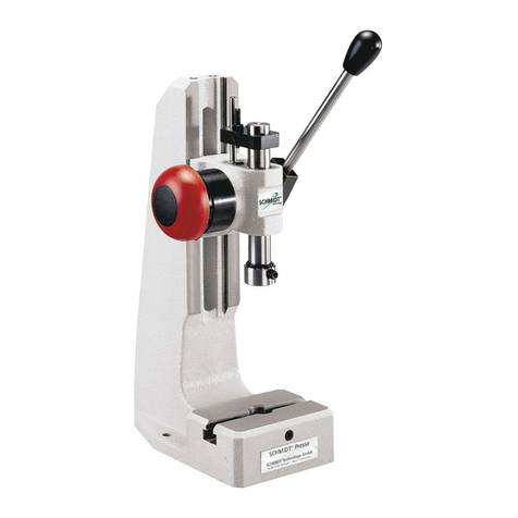
Schmidt ServoPress 605-660 User manual

Translation of the Original-Assembly Instructions
SCHMIDT®ServoPress
605-660

Further applicable documents
2SCHMIDT®ServoPress 605-660 –V1.1
Further applicable documents
This instruction for use contains information about the delivered press. The
essential information includes the following:
Mounting and commissioning of the press
Operation and functions of the press
Maintenance and servicing of the press
Information describing the press system used, its design, operation and
maintenance is contained in separate instructions.
For further information, refer to the "Instructions for Use - SCHMIDT Manual
workstation" respectively the "Assembly Instructions - SCHMIDT
Components for automation".
Information describing the control and its design is contained in separate
instructions.
For further information, refer to the operating instructions of the control unit.
Information about the user interface of the control unit and the integrated
functions is contained in separate instructions.
For further information, refer to the "Operating Instructions –SCHMIDT PRC
HMI".
Order-specific information can be found in the "Technical Documentation".
These can include:
Declarations of conformity or incorporation
Test protocols
Spare parts lists
Circuit diagrams
© 2020 SCHMIDT Technology GmbH
All rights reserved. Technical changes reserved.
Edition and revision date:
V1.1 - 09/2021

Table of contents
SCHMIDT®ServoPress 605-660 –V1.1 3
Table of contents
1Safety..................................................................4
1.1 Designated use.....................................................................................4
1.2 Organizational measures of the owner.................................................4
1.3 Residual risks........................................................................................5
1.4 Noise emission of the press..................................................................6
1.5 Standards and regulations....................................................................6
2ServoPress.........................................................7
2.1 Structure................................................................................................7
2.2 Function ................................................................................................7
3Assembly and start-up......................................8
3.1 Delivery .................................................................................................8
3.2 Transport...............................................................................................8
3.3 Installation of the press.........................................................................9
3.4 Mounting tools.....................................................................................11
3.5 Adjusting the working area..................................................................13
3.6 Connecting the press..........................................................................14
4Maintenance and servicing.............................15
4.1 Cleaning the press and the ram..........................................................15
4.2 Adjusting the force measurement.......................................................16
4.3 Lubricating the spindle........................................................................16
4.4 Filling the grease reservoir..................................................................16
4.5 Troubleshooting ..................................................................................20
4.6 Customer service................................................................................21
5Decommissioning and disposal.....................22
5.1 Decommissioning................................................................................22
5.2 Disposal ..............................................................................................22
6Appendix..........................................................24
6.1 Technical data.....................................................................................24
6.2 Life limit...............................................................................................25
6.3 Dimensions .........................................................................................26

1 Safety
4SCHMIDT®ServoPress 605-660 –V1.1
1 Safety
The press is designed and built in accordance with the valid safety
regulations and state-of-the-art methods and is tested for function and
safety. The press is/will be a component of the press system.
To ensure operational safety, note:
Chapter "Designated use"
Chapter "Organizational measures of the owner"
Chapter "Residual risks"
Chapter "Standards and regulations"
Independently of the indications specified in this manual, the current country
specific regulations regarding work safety and health protection are valid.
1.1 Designated use
The press can be used as follows:
As component in a SCHMIDT manual workstation during pressing
processes with manual loading and unloading.
OR
As part of a press system together with SCHMIDT components for
automation. In this case, the press system/tool has to be designed in
such a way that is not possible to reach into the hazard zone.
Any other use for any purposes other than those described above is
considered contrary to its designated use. The manufacturer cannot be held
liable for damages resulting from this.
Please do not make any changes to the components. The manufacturer
cannot be held liable for damages resulting from this. These changes are at
the sole risk of the owner.
Designated use also includes
compliance with the documentation and
compliance with the inspection and maintenance instructions of the
manufacturer
1.2 Organizational measures of the owner
The press may only be operated in technically perfect condition.
The instructions concerning start-up, operation and maintenance described
in this manual must be observed.
This manual must be stored within easy reach at the workplace.
The persons responsible for the work on the press must have read the
manual and, in particular, chapter "1 Safety" before starting work. This also
applies to persons who work on the machine only occasionally.
Manual
Personnel

1 Safety
SCHMIDT®ServoPress 605-660 –V1.1 5
The press must be operated, checked and maintained properly. The
competences for these operations must be defined clearly.
Use the press only if all the required protective devices have been installed
completely and are in a functional state. The protective devices must not be
bypassed or deactivated.
Depending on the working process, tool, size and work piece material, an
additional working area protection may be needed. The owner is responsible
for this.
According to the country-specific regulations, perform risk assessment and
take the appropriate safety measures if necessary.
1.3 Residual risks
Safe press operation requires proper interaction of press, control, pressing
tool, safety device(s) and action of the users in accordance with safety
procedures.
Certain places at the press cannot be protected without limiting the
functionality and usability of the press. Therefore, despite all constructive
safety measures, there is still a residual risk.
DANGER
Injuries or death caused by touching live parts
When carrying out assembly and maintenance work, you may come into
contact with parts that carry dangerous voltage during operation. Touching
live parts may cause death.
Any work on the electrical system or equipment must be carried out
only by trained electricians or by specially instructed persons under the
control and supervision of a trained electrician and in accordance with
the applicable electrical engineering rules and regulations.
WARNING
Risks for persons
When working with the press, the operator must not endanger
himself/herself or other persons.
Operate the press only if no other person is in the hazard zone.
WARNING
Risk of burns from heated parts
Press operations can heat up tools and workpieces. There is a risk of
coming into contact with the heated parts. This can result in burns to the
body. Heated parts can also cause fires.
Wear protective clothing.
Install an appropriate protective device.
Protective devices
Risk assessment

1 Safety
6SCHMIDT®ServoPress 605-660 –V1.1
Further information regarding the safe operation of the press can be found in
the corresponding chapters of this manual.
1.4 Noise emission of the press
WARNING
Different noise emission values
Noise emission values determined according to the EN ISO 16092-1
(Machine tools safety - Presses - Part 1: General safety requirements)
standard, Appendix F, may underestimate the noise emissions of the
machine under real operating conditions.
The noise level value emitted by the press can be found in chapter "6.1
Technical data".
Measures for noise reduction
The stroke speed of the press has a significant influence on the noise level
value. Reducing the speed reduces the noise emission.
For further information, refer to the "Instructions for Use - SCHMIDT Manual
workstation" respectively the "Assembly Instructions - SCHMIDT
Components for automation".
1.5 Standards and regulations
Some important standards and regulations to be observed when operating a
press are listed below.
However, this list serves merely for your information. SCHMIDT Technology
cannot be held liable for the completeness of this list.
Machine directive 2006/42/EC
EN ISO 12100 (Safety of machinery - General principles for design -
Risk assessment and risk reduction)
EN ISO 13854 (Safety of machinery - Minimum gaps to avoid crushing
of parts of the human body)
EN ISO 13857 (Safety of machinery - Safety distances to prevent hazard
zones being reached by upper and lower limbs)
EN ISO 16092-1 (Machine tools safety - Presses - Part 1: General safety
requirements)
EN ISO 16092-2 (Machine tools safety - Presses - Part 2: Safety
requirement for mechanical presses)

2 ServoPress
SCHMIDT®ServoPress 605-660 –V1.1 7
2 ServoPress
2.1 Structure
Figure 1: Structure (example)
1
Servo motor
2
Fan
3
Process data acquisition
4
Flange
5
Ram
6
Belt drive
2.2 Function
When using the ServoPress, the force of the servo motor is transmitted to
the ram via a backlash-free spindle drive.
The presses 605-617 are equipped with a ball screw. The presses 620-660
with a planetary roller screw.
The motor is controlled by the servo converter according to the parameters
(position, force and speed) defined in the control. Thus the ram travels along
the defined operating profile.
The servo converter and the power supply unit are located in a switch
cabinet.
The integrated brake is used as device for retention of ram in home position
and prevents the lowering of the ram in currentless condition.
In case of an overload, the ServoPresses 616-660 have a mechanical clutch
that separates the motor from the drive.
The maintenance-free, temperature-controlled fan built into the ServoPress
ensures highly reliable operation.
The "stroke" measurement is carried out via an absolute position measuring
system directly on the ram. The "force" signal is detected via an integrated
force sensor.
These signals are processed and evaluated in process data acquisition. The
results are then transmitted to the connected control unit.
Force/stroke-
monitoring

3 Assembly and start-up
8SCHMIDT®ServoPress 605-660 –V1.1
3 Assembly and start-up
CAUTION
Safety instructions
The press must only be installed and put into operation by a skilled
person.
Any work on the electrical equipment of the press must be carried out
only by trained electricians or by specially instructed persons under the
control and supervision of a trained electrician and in accordance with
the applicable electrical engineering rules and regulations.
Observe the dimensions, weights and setting values listed in the
manual or the data sheets.
Check the press, accessories and all supply lines for possible damage
prior to each start-up.
Switch off a defective press immediately and have the disturbances
repaired as soon as possible.
Improper transport, installation and commissioning is prone to accidents and
can cause damage or malfunctions to the delivered components for which
SCHMIDT Technology does not grant any liability or guarantee.
3.1 Delivery
Check the delivered components for visible transport damage.
Report any transport damage immediately to the following authorities:
the carrier
the dispatch department of SCHMIDT Technology
Packing
Keep the original packaging and transport aids, if present, for later
transports and/or for further storage.
3.2 Transport
Short internal transport distances reduce the risk of accidents.
Use sufficiently dimensioned transport equipment.
During transport, ensure that the component(s) are handled properly.
The components may only be transported on a suitable stable base (e.g.
pallet).
Do not lift the press at the tool magazine area or at mounted parts.
Secure loose parts accordingly before transport.

3 Assembly and start-up
SCHMIDT®ServoPress 605-660 –V1.1 9
3.3 Installation of the press
WARNING
Lifting heavy loads
If the lifting equipment or lifting gear is insufficiently dimensioned or
incorrectly attached, suspended loads may fall down.
Use a lifting equipment with sufficient load capacity.
Use a sufficiently dimensioned lifting gear to lift the component.
Do not step below suspended components.
WARNING
Falling loads
The lifting screw may become loose from the threaded hole due to
uncontrolled rotation during lifting.
Use pivot-mounted lifting screws.
Always mount all lifting screws for lifting.
Make sure that the component does not rotate during lifting.
The press must be installed safely (in terms of work safety) at its future
operating location.
The future operating location must be designed for the weight of the press,
including tools. Apart from weight of the press itself, the stress caused by the
working process (dynamics and vibrations) must be taken into account.
The space required for the press and any supply lines that may be present
must be taken into account.
Frame (optional)
Before start-up, the frame must be screwed down to the press base
(optional) or to another stable table plate.
For further information on the fastening bores and the weight of the
component, please refer to chapter "6.1 Technical data".
ServoPress 605
This frame can be lifted by hand.
ServoPress 616-660
To lift the frame, you need a lifting equipment.
If necessary, take the optionally delivered accessories out of the frame.
Mount the lifting screws at the frame.
Attach the transport equipment at the lifting screws.
Carefully lift the frame. The frame may swing out.
Operating location
Lifting the frame

3 Assembly and start-up
10 SCHMIDT®ServoPress 605-660 –V1.1
Pay attention to the center of mass of the frame.
Figure 2: Frame with lifting equipment (example)
Put the frame on the press base or on the.
Check if both axes of the frame are horizontal and compensate the
differences, if necessary.
Screw the frame down on the press base or on the mounting plate.
Press
Before start-up, the press must be screwed down to the frame or to another
stable frame system.
For further information on the fastening bores and the weight of the
component, please refer to chapter "6.1 Technical data".
ServoPress 605
This press can be lifted by hand.
ServoPress 616-660
To lift the press, you need a lifting equipment.
Screw the lifting screw(s) into the threaded hole(s) provided for this
purpose. This is/are located on the top of the press.
Fasten the lifting gear to the lifting screw(s).
Figure 3: Top view of a press
1
Lifting screws
Mounting the frame
Lifting the press

3 Assembly and start-up
SCHMIDT®ServoPress 605-660 –V1.1 11
Place the press onto the frame/frame system.
Make sure that the fastening holes of the press are lined up precisely
with the holes in the frame/frame system.
Screw the press tightly from below with the following torques.
Use screws with the appropriate property class.
Press type
Screw
Property class
Torque
605
4 x M5x25
10.9
8 Nm
616
4 x M6x25
10.9
14 Nm
617
4 x M8x35
10.9
32 Nm
620
4 x M12x50
12.9
135 Nm
650
6 x M14x60
12.9
215 Nm
660
10 x M14x60
12.9
215 Nm
CAUTION
Dimension of frame system not suitable
If you ordered a press without the standard frame from SCHMIDT
Technology, you must install the press onto a suitable frame system. If the
frame system is not adequately dimensioned, problems such as the
production of defective parts or even damage to the press system can
occur.
Choose your frame system according to the maximum force of your
press.
Observe the dimensions and weight of the press used.
3.4 Mounting tools
DANGER
Injuries caused by closing tools
When working with the press, there is a risk that persons will interfere with
the closing action of the tools. This may result in injuries such as crushed
fingers and hands.
Take necessary safety measures that prevent persons from interfering
with the closing action.
Inform the personnel about this source of risk!
Upper tool
CAUTION
Construction of the tools
The owner or the entrusted construction engineer must make sure that the
construction of the tools complies with the safety regulations and that the
necessary safety measures will be observed.
Observe the maximum allowed weight for the upper tool.
Mounting the press

3 Assembly and start-up
12 SCHMIDT®ServoPress 605-660 –V1.1
You will find ram dimensions, the maximum dimensions and the maximum
weights for the upper tools in chapter "6.1 Technical data".
For mounting the upper tool, a centric dowel pin hole with a set screw is
available for fixing it.
Insert the clamping pin into the dowel pin hole of the ram.
Fasten the upper tool using the set screw.
Figure 4: Fastening options at the ram (example)
1
Set screw
2
Dowel pin hole
The ram has a distortion lock for the upper tool.
Figure 5: Distortion lock on the ram (example)
1
Slot (ServoPress 605)
2
Dowel hole (ServoPress 616-660)
3
Threaded hole (ServoPress 616-
660)
Lower tool
For mounting the lower tool, a table bore and a T-slot are available.
Place the lower tool on the table plate.
Screw the lower tool down to the table plate.
Figure 6: Frame with table plate (example)
1
Table bore
2
T-Slot
For frames with a screwed fixture mounting plate, the fixture mounting plate
is aligned with the ram but not pinned.
Distortion lock

3 Assembly and start-up
SCHMIDT®ServoPress 605-660 –V1.1 13
3.5 Adjusting the working area
Constructive restrictions
CAUTION
Damage to the press or to the tool
The available operating stroke is limited by various system functions (e.g.
initialization/ reference run, spindle lubrication, etc.). These system
functions move the ram above or below the topmost position.
Make sure that the execution of system functions does not result in
collisions with the tool or tools.
During tool construction, include a corresponding adapter in the
planning if necessary.
After the reference run, which is used to tare the force measurement, the
ram moves to the TDC position. The taring takes place via the spindle
rotation.
If the reference run is started in a position ≥ the value under point 3 "Max.
stroke during reference run from home position", the stroke is ended 0,5 mm
above the parameterized TDC position.
Figure 7: Restrictions of the working stroke (example)
Press
605
616
617
620
650
660
1Ram extension at home
pos. (top working pos.) [mm]
40
50
60
60
60
67
2Max. negative stroke [mm]
- 20,5
- 22,2
- 21,9
- 15,4
- 7
0
3Max. stroke during ref. run
from home position * [mm]
+ 5,5
+ 5,5
+ 11
+ 5,5
+ 11
+ 22
* If the reference run is not started from the home position but lower, the ram moves in negative
direction.
Adjusting the working stroke
The individual parameters of the working stroke are defined in the control
unit.
For further information, refer to the "Instructions for Use - SCHMIDT Manual
workstation" respectively the "Assembly Instructions - SCHMIDT
Components for automation".
Ram extension at home
position

3 Assembly and start-up
14 SCHMIDT®ServoPress 605-660 –V1.1
3.6 Connecting the press
DANGER
Injuries or death caused by touching live parts
When carrying out assembly and maintenance work, you may come into
contact with parts that carry dangerous voltage during operation. Touching
live parts may cause death.
Any work on the electrical system or equipment must be carried out
only by trained electricians or by specially instructed persons under the
control and supervision of a trained electrician and in accordance with
the applicable electrical engineering rules and regulations.
All connections of the press are labeled.
Observe the enclosed circuit diagram.
Figure 8: Connections (example)
1
A10/X1 power (orange)
2
A10/X2 encoder (green)
All connections of the process data acquisition are labeled.
Observe the enclosed circuit diagram.
Figure 9: Connections (example)
1
X1 EtherCAT-P In
2
X2 EtherCAT Out
3
X3 Data
Press
Process data
acquisition

4 Maintenance and servicing
SCHMIDT®ServoPress 605-660 –V1.1 15
4 Maintenance and servicing
CAUTION
Safety instructions
The press must only be serviced by a skilled person.
Any work on the electrical equipment of the press must be carried out
only by trained electricians or by specially instructed persons under the
control and supervision of a trained electrician and in accordance with
the applicable electrical engineering rules and regulations.
All spare parts must comply with the technical requirements specified
by SCHMIDT Technology. This is always guaranteed in the case of
original spare parts.
Unless expressly described otherwise, do not start with the maintenance and
servicing work until
the press has been disconnected from the power/voltage supply,
the press system has been switched off and secured against being
switched on again,
the dangerous movements have come to a standstill,
unauthorized, inadvertent or unexpected starting of dangerous
movements as a result of stored energy is prevented.
Interval
Activity
Every week
(every 50 operating hours)
see chapter "4.1 Cleaning the press and the ram"
Every year
(every 3,000 operating hours)
see chapter "4.2 Adjusting the force measurement"
Automatically
(suggested by the control)
see chapter "4.3 Lubricating the spindle"
Automatically
(suggested by the control)
see chapter "4.4 Filling the grease reservoir"
Further information about the necessary activities you get in the individual
chapters.
4.1 Cleaning the press and the ram
CAUTION
In any case do not use any solvent based cleaners.
Clean the press with a lightly oiled cloth.
Move the ram to the BDC position.
Maintenance intervals
Press
Ram

4 Maintenance and servicing
16 SCHMIDT®ServoPress 605-660 –V1.1
Clean the ram with a lightly oiled cloth.
Clean the scale on the ram with a soft, lint-free cloth wetted with
isopropyl alcohol.
4.2 Adjusting the force measurement
Since the force-measuring system is usually used for measuring
characteristic quantities relevant to quality, it should be calibrated and, if
necessary, adjusted at reasonable intervals established by the owner. EN
ISO 9001 (Quality management systems - Requirements) makes a
calibration of the system mandatory at regular intervals.
Calibration is also offered as a service by the SCHMIDT Customer Service.
4.3 Lubricating the spindle
The lubrication of the spindle is stroke-dependent. Depending on the
configured operating profile, the point in time for the next lubrication is
calculated. When the given time has come, the control will request you to
lubricate.
For further information, refer to the "Instructions for Use - SCHMIDT Manual
workstation" respectively the "Assembly Instructions - SCHMIDT
Components for automation".
4.4 Filling the grease reservoir
WARNING
Shearing of finger(s)
The upward or downward movement of the used grease depot or spindle
nut creates a danger zone during operation of the press. Fingers can be
sheared off when reaching into this danger zone.
Mount the inspection cover on the inspection opening before switching
on the press system.
NEVER operate the press without the inspection cover installed.
If the grease reservoir is almost empty, a message to refill the grease
reservoir is displayed.
To fill the grease reservoir, the ram of the press moves to a special position.
This happens automatically after answering the message.
If you are prompted ...
Switch off the press system with the main switch on the switch cabinet.
ServoPress 605-620
For the ServoPresses 605-620, the grease reservoir must be filled manually
using the lubrication nipple.
There is an inspection opening at the front of each press. Underneath is
Switching off the press
system

4 Maintenance and servicing
SCHMIDT®ServoPress 605-660 –V1.1 17
the used grease reservoir
the lubrication nipples (ServoPress 605-620)
Figure 10: Inspection opening (example)
1
Inspection cover
2
Cover used grease reservoir
3
Used grease reservoir
4
Lubrication nipples
During each lubrication process, old, used grease is automatically
transported to the used grease reservoir.
Dismount the inspection cover.
Dismount the cover of the used grease reservoir.
Remove the used grease from the reservoir.
Clean the used grease reservoir and the cover of the used grease
reservoir.
The grease reservoir must be filled with a grease gun.
Remove the cover of the lubrication opening (only ServoPress 620).
Use a grease gun to press in grease at the lubrication nipple.
Insert the cover in the lubrication opening (only ServoPress 620).
Press type
Amount of
grease
required
Grease
Material no.
605
28 cm3
KLÜBERPLEX BEM 34-131N
554906 (grease
cartridge)*
616
44 cm3
KLÜBERPLEX BEM 34-131N
554906 (grease
cartridge)*
617
64 cm3
KLÜBERPLEX BEM 34-131N
554906 (grease
cartridge)*
620
69 cm3
KLÜBERPLEX BEM 34-131N
554906 (grease
cartridge)*
* A maintenance set (material no. 564524), which includes a grease gun, a grease cartridge and
a hose, is optionally available.
Cleaning the used
grease reservoir
Filling the grease
reservoir

4 Maintenance and servicing
18 SCHMIDT®ServoPress 605-660 –V1.1
CAUTION
Contamination of the machine
If the lubrication opening is not covered up again after finishing lubrication,
the functioning of the press can be affected by increasing contamination.
Before starting the press system, insert the cover on top of the
lubrication opening.
Mount the cover of the used grease reservoir.
Mount the inspection cover.
ServoPress 650-660
For the ServoPresses 650-660, the spindle and the spindle bearing is
automatically lubricated via an integrated grease gun.
If the grease cartridge of the grease gun is almost empty, it must be
replaced.
Figure 11: Inspection opening (example)
1
Inspection cover
2
Cover used grease reservoir
3
Used grease reservoir
During each lubrication process, old, used grease is automatically
transported to the used grease reservoir.
Dismount the inspection cover.
Dismount the cover of the used grease reservoir.
Remove the used grease from the reservoir.
Clean the used grease reservoir and the cover of the used grease
reservoir.
Mount the cover of the used grease reservoir.
Mount the inspection cover.
Remove the back cover of the press.
Loosen the grease gun mounting screw.
Cleaning the used
grease reservoir
Replacing the grease
cartridge

4 Maintenance and servicing
SCHMIDT®ServoPress 605-660 –V1.1 19
Swing the grease gun out of the housing.
Pay attention to existing cables and hoses.
Press the unlocking lever on the grease gun.
Fully extend the plunger rod.
Unscrew the grease gun housing.
Remove the empty grease cartridge.
Remove the covers on the new grease cartridge.
Place the new grease cartridge into the grease gun housing in the
direction of the arrow.
Screw the grease gun housing into place.
Make sure that the housing is properly secured.
Push the plunger rod completely into the grease gun.
Swing the grease gun into the housing.
Pay attention to existing cables and hoses.
Secure the grease gun via the mounting screw.
Carefully loosen the bleed screw and bleed the grease cartridge.
Tighten the bleed screw again hand-tight.
Reinstall the back cover of the press.
Figure 12: Replacing the grease cartridge (example)
1
Back cover
2
Plunger rod
3
Unlocking lever
4
Grease gun
5
Bleed screw
6
Mounting screw
Press type
Amount of
grease
required
Grease
Material no.
650-660
400 cm3
KLÜBERPLEX BEM 34-131N
554906 (grease
cartridge)

4 Maintenance and servicing
20 SCHMIDT®ServoPress 605-660 –V1.1
Starting the press system
Switch on the press system with the main switch on the switch cabinet.
After restarting the system, a message is displayed whether grease has
been refilled.
If you acknowledge the message by pressing the "Yes" button, the press
system is again ready for operation.
If you acknowledge the message by pressing the "No" button, you must
repeat the entire process.
CAUTION
Damage to the press
If the message was acknowledged by pressing the "Yes" button but no
grease has been filled, you will damage the press. Increased friction will
result in the destruction of the spindle and the spindle bearing.
Fill the grease reservoir as soon as the system issues the request.
Replace the grease cartridge as soon as the system issues the
request!
Use only full grease cartridges for replacement purposes.
4.5 Troubleshooting
Fundamental functions are automatically monitored by the press. A flashing
signal on the ring-shaped status display of the process data acquisition
indicates the various operating states.
Figure 13: Status display (example)
1
Status display "X1"
2
Status display "X2"
3
Status display "X3"
24 V DC / EtherCAT inactive
INIT / No LINK
INIT / LINK OK & No ACT
INIT / LINK OK & ACT OK
Pre-Operational
Safe-Operational
Press ready
Process data acquisition
RangeCalc
Press not referenced
FW-Update (Bootloader active)
FW-Update (FoE in FW active)
Table of contents
Other Schmidt Power Tools manuals

Schmidt
Schmidt 4 User manual

Schmidt
Schmidt HydroPneumaticPress User manual

Schmidt
Schmidt ADS 250 User manual

Schmidt
Schmidt 3 User manual

Schmidt
Schmidt 343 User manual

Schmidt
Schmidt ManualPress 300 Series User manual

Schmidt
Schmidt 3 User manual

Schmidt
Schmidt 4 User guide

Schmidt
Schmidt AmphiBlast 120 User manual
Popular Power Tools manuals by other brands

RGN
RGN CN70 operating manual

Chicago Electric
Chicago Electric 67632 Set up and operating instructions

EINHELL Bavaria
EINHELL Bavaria BAS 14,4-2/1H operating instructions

Campbell Hausfeld
Campbell Hausfeld CHN10302 operating instructions

Toshiba
Toshiba KK-1600 Service manual

wurth
wurth Master STP 85 operating instructions