Mailing address:
P. O. B. 1154
84464 Waldkraiburg Germany
Shipping address:
Schichtstr. 16
84478 Waldkraiburg Germany
Phone:
int. + 49 / (0)8638 / 9410-0
Fax:
int. + 49 / (0)8638 / 4825
int. + 49 / (0)8638 / 67898
e-mail:
Internet:
http://www.hans-schmidt.com
Unit displayed
9 1/min rotations per minute.
10 Hz frequency of motion per second.
NOTE! When an external trigger signal is used, the units 1/min (rather than FPM) or Hz are
displayed.
Operating information
12 RANGE external trigger signal is causing the ash frequency to be too high.
13 EXT external trigger signal selected.
14 INT device is generating ash frequency.
NOTE! A parameter which has been set to differ from the default setting ashes during ope-
ration.
Instructions on the use of special device functions in the version with
trigger connection (DSL-300-T)
DELAY ms
Adjustment of delay time between the internal trigger signal and the ash (in milliseconds). This
function enables you to set a xed delay time between the input signal and the output signal.
Example: The external trigger signal is generated before the required observation point
(= ash position of the stroboscope). In this case the connected stroboscope would regularly
ash too soon. With the DELAY ms function, you can set the value by which the output signal
should be delayed.
PHASE deg
Phase shift adjustment between the internal trigger signal and the ash (in degrees, relative to
the frequency). This function enables you to set a xed angle between the internal trigger signal
and the ash.
Example: The external trigger signal is generated before the required observation point (=
ash position of the stroboscope). In this case the connected stroboscope would regularly ash
too soon. With the PHASE deg function, you can adjust the delay so that the ash position of
the stroboscope is altered by a set angle. This setting is independent of the current speed of
rotation, which means that the stroboscope will ash at the required position even during the
start-up process or when the speed of rotation is uctuating.
DIV (pulse divider)
This function is only active when an external trigger signal is employed. With the pulse divider
you can set a value x, by which the external trigger signal is then divided.
Example: An external trigger (e.g. rotation sensor) scanning a gear wheel issues a signal for
every tooth scanned. At a DIV value of 10, only every tenth input pulse is transmitted to the
connected stroboscope as a trigger signal.
OPT
Trigger signal edge selection. 0 = positive edge, 1 = negative edge. With this option, the polarity
of the trigger signal can be dened.
9. Additional operating information for the version with
trigger connection (DSL-300-T)
ATTENTION! Do not use signals over 300,000 FPM Hz to trigger the device.
INFORMATION! The device must be switched manually between external and internal trigger
signal.
RECOMMENDATION: Only use original material from the manufacturer for trigger signal con-
nection.
Terminal connection assignment – trigger jack (Figure 2)
ATTENTION! Please observe the terminal connections shown in the terminal connection dia-
gram (Figure 2).
The trigger input is potential-free. The potential-free input is suitable for PNP and NPN signals.
A cable with plug, corresponding to these input jacks, is provided with the device.
Figure 2
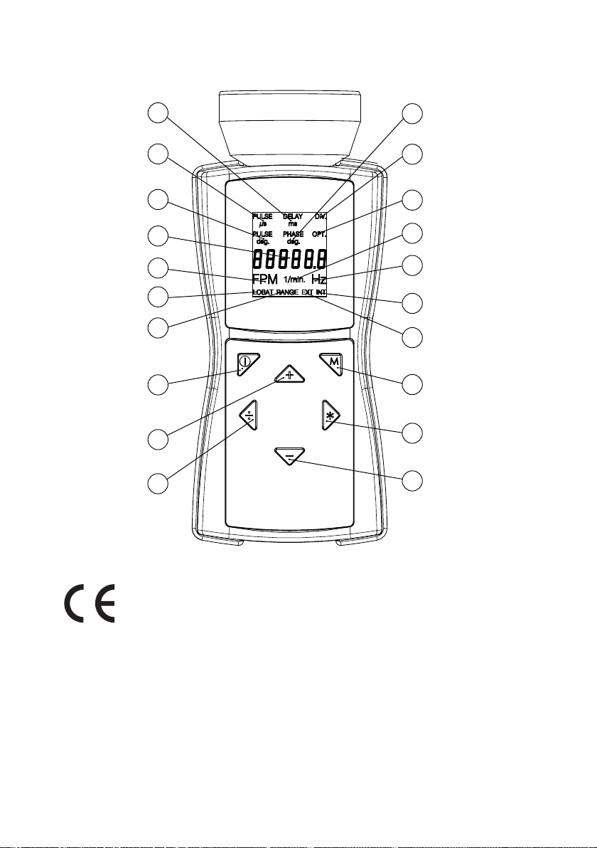
Position of buttons (Figure 1)
The following functions are activated by simultaneously pressing the buttons shown below:
B + D = switch between internal and external trigger signal.
Display elds (Figure 1)
Inuencing the input signal before the ash is generated
3 DELAY ms adjustment of delay time (in milliseconds) between the internal trigger signal
and the ash.
4 PHASE deg phase shift adjustment between the internal trigger signal and the ash
(in degrees, relative to the frequency).
5 DIV pulse divider, maximum value 255.
6 OPT trigger signal edge selection
0 = positive edge
1 = negative edge
Trigger input
3 … 32V
BROWN
BLUE Trigger output
max. 50mA
WHITE
BLACK